

Interior LED Changeover (uhm...Looooong)
 04-27-2012, 02:45 AM
#91
Addict
Rennlist Member
Rennlist Member
Paul, thanks for sharing your experience with this.
Hope you're settling on a solution that works for you.
I didn't need to do that, but in my write-up, I did mention that those WLED-WHP5 bulbs (using the original brown twist-lock sockets) are best inserted after the bulb PC board is reattached to the white plastic piece and you still need to jiggle them a little to get them inserted.
Of course, the bulbs you got might have been ever so slightly different. It seems that the manufacturing tolerances on these bulbs aren't real tight.
I recommended the B8.4D-AHP (amber for the four uppers) and B8.4D-RHP (red for the four lowers). Note the "HP" (high power) suffix; these are both brighter and have a more even, wider field. Believe me, I did a lot of experimenting with different products before coming up with my recommendations.
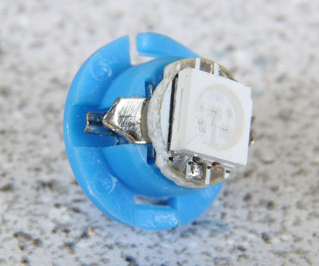
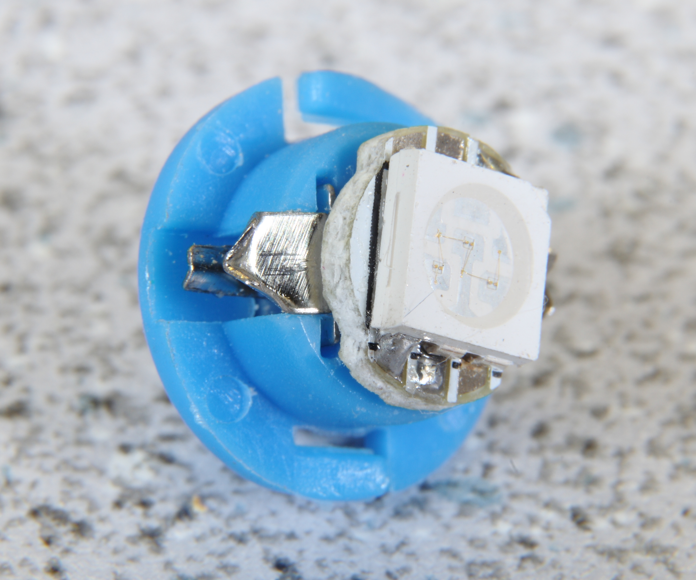
The B8.4D-xHP versions look like this (this happens to be a blue one; you'll want amber and red for the LCD "information display" backlighting):
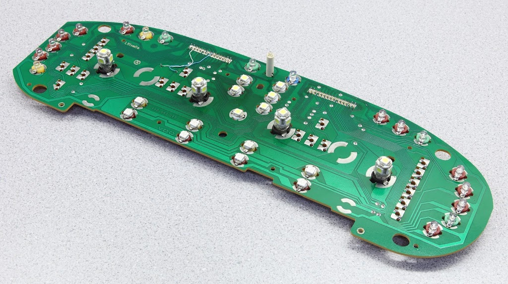
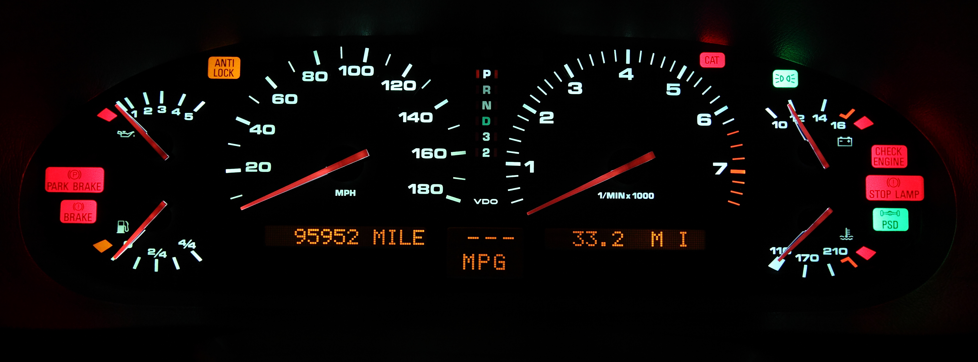
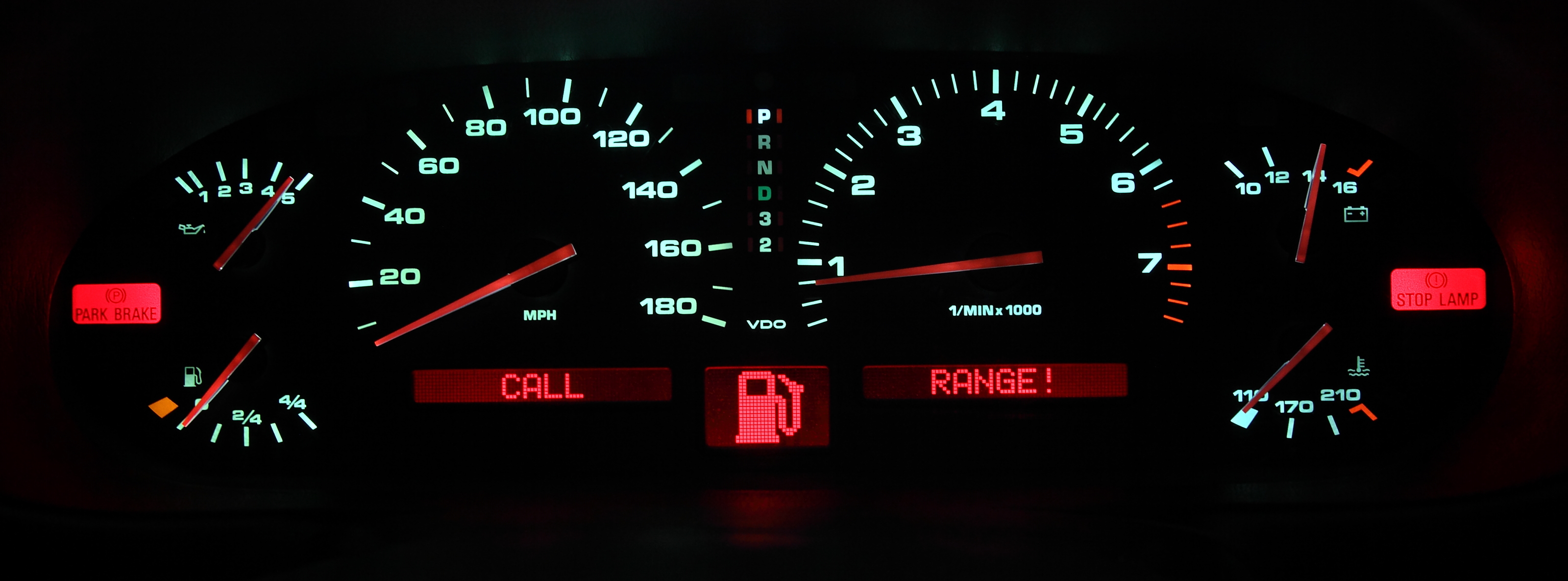
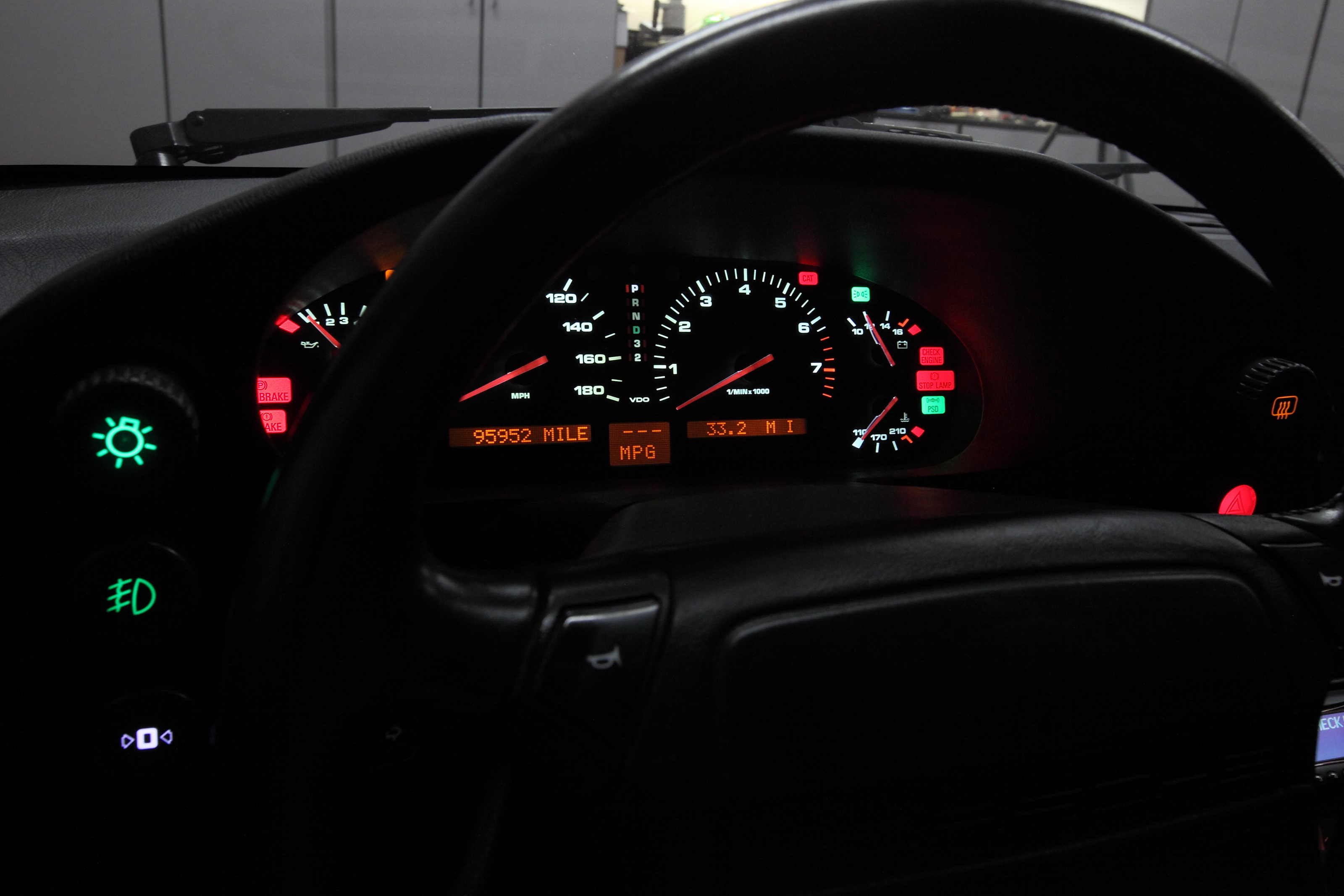
I've already posted these photos in other threads, but a fully populated instrument cluster bulb PC board using the LED bulbs I recommend looks like this:
(Click any of these photos to see them in their full high-res glory)

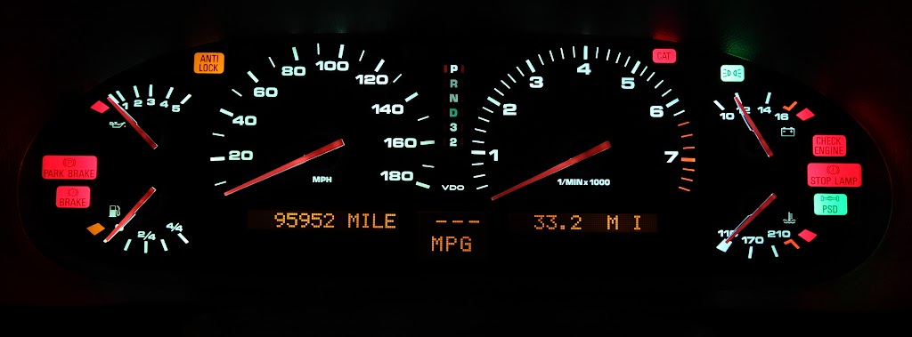
And you'll see that it's rather nice, even lighting; the info display backlighting isn't perfectly even, but it's pretty darn good.
The photos don't quite do it justice, either. It's hard getting good photos of the cluster in the dark, and I've noticed that LEDs show some weird color shifting and brightness differences in photos that you cannot (or can barely) see in person.


Hope you're settling on a solution that works for you.
1. I also used the WLED-x5 lamps for the backlights. In order to allow these to fit through the stock holes, I had to grind down the side LEDs a bit with a drum sander on a Dremel. No harm from the sanding, though... if anything, it provides a bit of an improvement in lateral dispersion. I also found that I had to push the leads all the way to the outside, at the bottoms of the lamps, in order to get them to make contact with the contacts in the holders.
Of course, the bulbs you got might have been ever so slightly different. It seems that the manufacturing tolerances on these bulbs aren't real tight.
2. I bought green and red lamps for the LCD display. In the end, though, I decided to stick with the stock incandescents, as the LEDs (the cheaper/dimmer B8.4D's) while being a good brightness, still made for too much of a spotlit (i.e. uneven) backlighting of the LCD panels.
The B8.4D-xHP versions look like this (this happens to be a blue one; you'll want amber and red for the LCD "information display" backlighting):
I've already posted these photos in other threads, but a fully populated instrument cluster bulb PC board using the LED bulbs I recommend looks like this:
(Click any of these photos to see them in their full high-res glory)


And you'll see that it's rather nice, even lighting; the info display backlighting isn't perfectly even, but it's pretty darn good.
The photos don't quite do it justice, either. It's hard getting good photos of the cluster in the dark, and I've noticed that LEDs show some weird color shifting and brightness differences in photos that you cannot (or can barely) see in person.


The following users liked this post:
XLR82XS (07-06-2022)
04-27-2012, 09:40 PM
#93
Three Wheelin'
Join Date: Mar 2010
Location: Colorado Springs, CO USA
Posts: 1,307
Likes: 0
Received 3 Likes
on
3 Posts
Looks like you're using the WLED-x5HP's in that shot. The regular WLED-x5's use lensed LEDs rather than surface mount ones.
I had thought about amber, but when I shined a light through the LCD (power off) it transmitted more green, so I that's why I went with green. From your shots, I think the amber probably is a better call, though.
Thanks for sharing.
Paul
I had thought about amber, but when I shined a light through the LCD (power off) it transmitted more green, so I that's why I went with green. From your shots, I think the amber probably is a better call, though.
Thanks for sharing.
Paul
02-05-2013, 06:40 PM
#95
I am nearing the end of my dash LED conversion, and all that is left to do is the switches. I was looking for the blue/black wires on each of the switches, but I noticed that on the 4 way flasher switch there are two blue/black wires. Can I solder the resistor to either of those wires? I just want to make sure before I dive in head first. Thanks!
02-05-2013, 06:49 PM
#96
Addict
Rennlist Member
Rennlist Member
I am nearing the end of my dash LED conversion, and all that is left to do is the switches. I was looking for the blue/black wires on each of the switches, but I noticed that on the 4 way flasher switch there are two blue/black wires. Can I solder the resistor to either of those wires? I just want to make sure before I dive in head first. Thanks!
I'll just quote (and bold the most relevant parts) an exchange from another thread that answers the question:
hi Ed...can you clarify the purpose of the resistors on the pod switches.
is it to establish a preset level of brightness when the lights are turned. from that level the dimmer would take them dimmer but never any brighter.....i think that is the reason.
with my lights off, the only switch lit is for the headlights....as it should be. I dont have any other "residual" voltage that would cause any other pod light to light up or faintly glow.
my hazard unit (87s4) has two black/blue wires...do i place a resistor on both.
thnx
In the case of any switches with two BK/BL wires, the resistor goes between the switch contact and the two wires (the two existing wires are just daisy chaining to elsewhere and you want to preserve that connection without any resistance).
02-05-2013, 07:26 PM
#97
Thanks for the reply, and thanks even more for the excellent guide! I wouldn't have even attempted the conversion without it.
In the case of my two black/blue wires, they are both joined inside the switch. Short of trying to pull out the wires and re-connect them, could I just put a resistor on each wire?
In the case of my two black/blue wires, they are both joined inside the switch. Short of trying to pull out the wires and re-connect them, could I just put a resistor on each wire?
02-05-2013, 07:45 PM
#98
Addict
Rennlist Member
Rennlist Member
After you strip enough to solder to (and remembering to put the heat shrink tubing on before soldering!), just twist each pair of two wires back together again along with the end of the resistor, e.g.Code:
             /----BK/BL wire 1----\                /----BK/BL wire 1----
term. 58 ----|                    |----resistor----|
             \----BK/BL wire 2----/                \----BK/BL wire 2----
02-17-2013, 12:35 PM
#100
Racer
Question: what bulbs does one use to replace down next to the AT shifter in earlier cars? They're different from others used throughout the car, and emit a horribly dated orange glow and I want to change them to LED.
02-17-2013, 08:38 PM
#101
Addict
Lifetime Rennlist
Member
Lifetime Rennlist
Member
 02-17-2013, 08:40 PM
#102
Racer
02-23-2013, 10:08 PM
#103
Addict
Lifetime Rennlist
Member
Lifetime Rennlist
Member
Its a bit OT in the fact its an exterior LED but what is the bulb type for replacing the reverse lights...
I know i have seen it on here some where but the search eludes me this time.
I know i have seen it on here some where but the search eludes me this time.
02-24-2013, 12:56 AM
#104
Addict
Rennlist Member
Rennlist Member