When you click on links to various merchants on this site and make a purchase, this can result in this site earning a commission. Affiliate programs and affiliations include, but are not limited to, the eBay Partner Network.
Damn I remember those now. Sorry my memory is crap any more. You sent me info on these a while back. Probably earlier in this thread. Thanks for the info again. LOL.
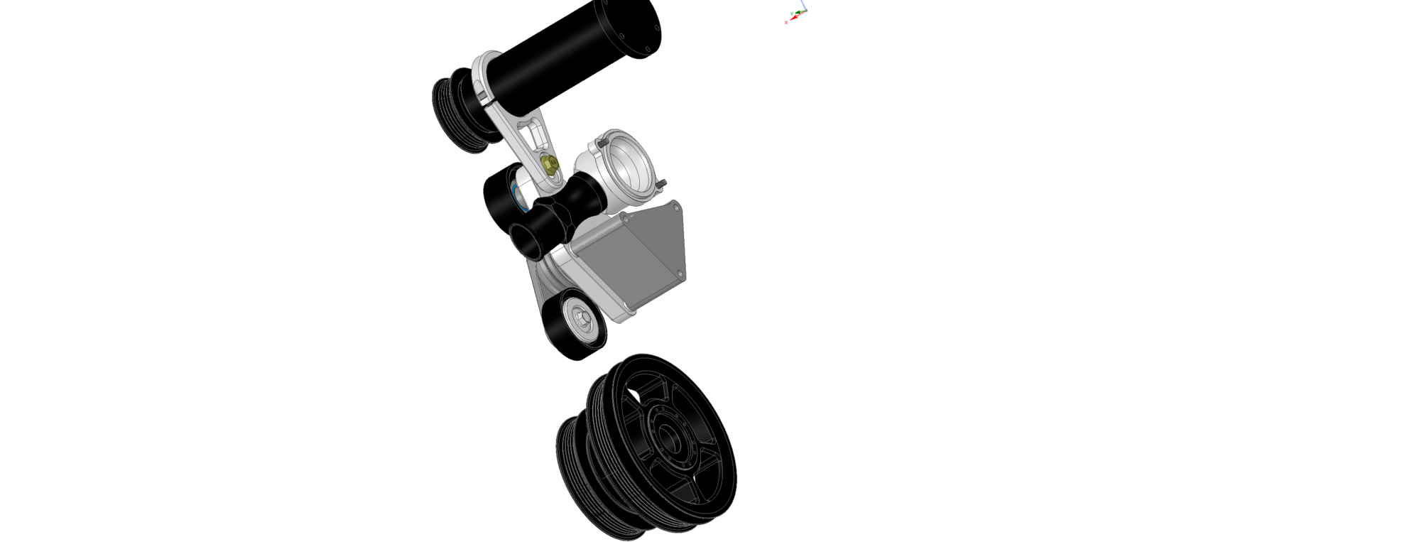
I am still waiting on the tensioner brackets to come back from the machine shop. My lathe guy (he machined the supercharger pulleys) wanted to bid them, but he had too big a work load, so sent them to one of my favorite shops in TX (the guy that machines my motor mounts and shifter parts). He does a quick turnaround, so hoping to get those back soon. I made some updates to the tensioner design while I was waiting for the quote from the first shop, so I will am attaching some renderings of the version out for machine now. Here is a webviewer link for the tensioner system in 3D:
The current version of the tensioner bracket supports both the OEM Dayco tensioner, as well as the American Racing Solutions billet tensioner. I have talked with them, and they are willing to sell a "private label" version of their tensioner for this project. When the brackets come back from the shop, I will start talking to those on the pre-order list to see if they want the billet or cast OEM tensioner. It would have to be a group consensus to place the purchase order for the billet tensioners. The adjustment in the bracket was also moved to just the snout support. There is a radial sliding grove for the supercharger offset complemented by a clamping function at the snout to positively couple the support to the bracket.
The thermostat housing has been printed and tested. It has a swivel functionality for future projects, and uses a -20ORB fitting for use with many fittings, including the Meziere WN series fittings as shown in the model. The stock radiator hose can be used by just removing the first 75mm of factory flared hose.
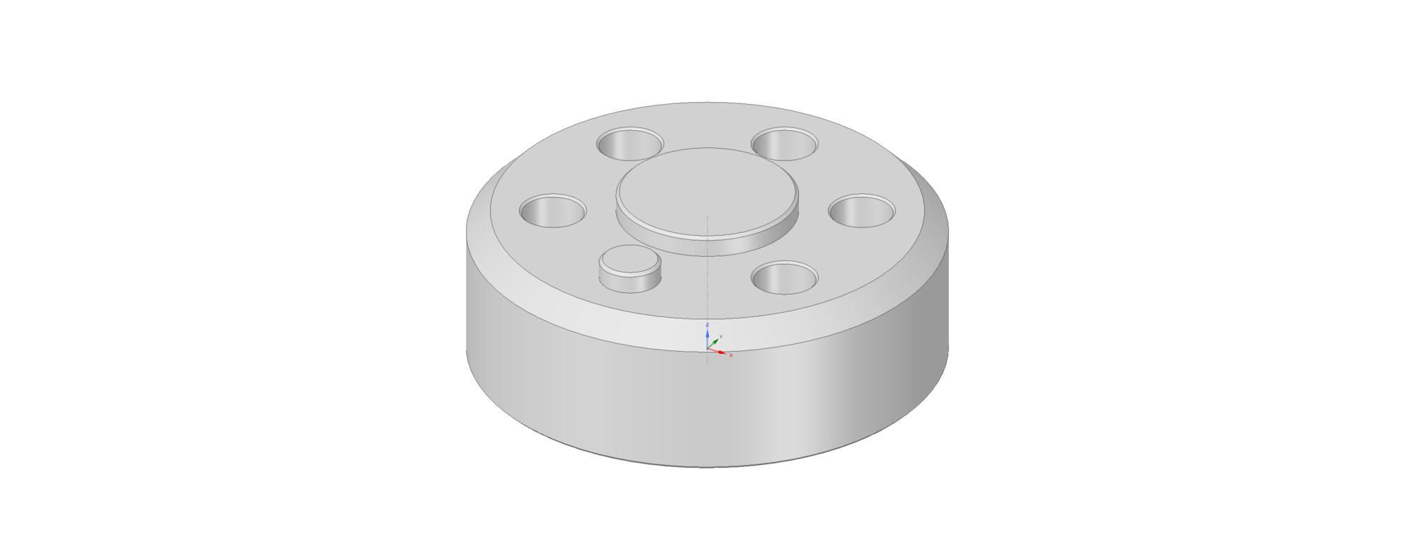
Also, the offset spacer for the PS pulley has been printed, test fit, and validated. It is also out for machining now. This spacer installs under the factory pulley, and moves it out to the new position on the supercharger crank pulley.
I have purchased several new 3D printers for making the air filter housings and several other air ducting components. These allow me to print in carbon-fiber and fiberglass reinforced materials.
The last major mechanical hurdle is the throttle inlet. I have been trying to find a way to reduce the cost and complexity with using a single throttle blade and the symmetrical intake system.
Chris did I see a "levitating" SC 928 w/ your signature on it
How about some more pic'c of your project?
Looking good Han's happy to see your project moving forward, and those new printers, cool
Dave
Hey Dave, it's getting closer. I'll try and shoot some pics this evening. Dealing with lots of minutia in the engine bay. Since so much is non stock and I have made further changes some things are fighting over the same real estate. I've had to rethink a few items. Nothing major, but time consuming nonetheless. I pulled a muscle in the right side of my chest, so I'm kinda stuck for the moment working topside. I can't crawl under the car until it heals up some. Literally takes my breath away when I lay down on the concrete. I still have starter to install then clutch and new x-pipe. then radiator and new fan shroud from Hans. Plus gas tank, pumps, & lines at the rear. Then maybe I can start it. LOL. Still a long punch list, but it's slowly getting there. I would really love to have it drivable for SITM but I'm not banking on it.
I will try and get a good update posted this week.
Give me a day or two. Have been focusing on the design of the throttle system... again. Redesigned it to try and make it cheaper to machine. Its deeper, so needed to look at the linkage again. Designed smaller linkage arms with built-in stops and idle adjusters, and printed them last week to test. Hoping to get it all wrapped up so I can have the "cheaper" version quoted as a whole.
Hey Brian,
Is that a John Kuhn setup? Those look like the ones that he would buy from KN and then modify. Currently, I am using smaller filters because I live at an elevation of 5000 feet and can get away with it. Eventually, I would like to go to larger filters in case I ever need to drive at sea level.
Good luck with you search.
Ralph
Can anyone identify the K&N part number for these filters? I guessed wrong and the one I got is too large for the space ahead of the radiator.
There are many ways to set up the filters like that, and so far I've seen only one out of many that has any chance of flowing enough for a supercharged engine and that fabricated with the supports that allow it to last reliably. That lobster claw cold air intake looks deceptively simple, but to do it right is neither cheap or simple.
Just so no one things the last itteration of the twinscrew kit is dead, I have been working on the dreaded throttle plenum quite a bit. I hit a couple small but significant snags, including a bearing selection issue. The bearings I wanted to use are no longer available, and there is no interchange for them. So, I redesigned the throttle housing to use the same INA double-sealed needle bearings that the factory 928 throttle and flappy use. Those are somewhat hard to source, but readily available.
Changing the size of the bearings,effected the housing, and had to go back and redo all the offsets for the linkage.... so something that seemed simple actually had a lot of small repercussions.
My goal for this kit is to be as fast to install and service as possible. Scrutinizing all the details in advance makes all the difference when it comes time to install. To that end, the clearance between the back of the throttle-inlet and the firewall is pretty narrow. The regulator I would use in an ideal world just wont fit with ample clearance. I ordered two more regulators to mock up, they will be here Monday and I can see which of the batch in my collection is the winner and add the appropriate mounting holes or design a bracket to mount to the inlet. I also had to make the difficult decision to move the planned location for the TMAP sensor to allow plenty of clearance for the throttle and kickdown cables. To do this, I had to design an adapter to fit in the Bosch TMAP footprint and convert that to a 1/8-NPT bung, which I will use as a dedicated reference feed for the fuel regulator. The TMAP will be moved to the passenger side, which will require the upper manifolds to go back to the machine shop to have that featured machined.
I also decided to move the factory location of the charcoal vent solenoid back in series with the vacuum solenoid and then plumb it into the passenger side of the throttle inlet. This reduces the congestion of hoses on the drivers side, and will also significantly tidy up the front of the engine bay (the flappy solenoid, tank vent solenoid, temp I sensor, front damper, oil fill neck and all the factory lines to the filler neck have been relocated or eliminated).
The new IAC (Using a Ford sourced unit) adapter has been redesigned to also include a vacuum distribution block with a large feed for the brake booster in an ideal location for easy removal when servicing the manifold. Similarly, the fitting for the "Christmas Tree" has also been located to this block, and will have a quick release. All lines connecting the manifold assembly to the chassis will now have push-connect style quick releases, and all the electrical connectors have been relocated to accessible positions. The hope is to make the manifold so quick and easy to remove, that ANY service that could be required will be easily completed on the bench. It also allows the entire intake system to be shipped assembled making the install super quick.
Hoping to have some good parts for show and tell at SITM.
This is good to hear that there is progress. While you have much time involved, there are those of us who have invested significant $$ and are waiting on delivery.

 01-08-2018, 11:39 PM