
Crankshaft seized after Trans Repair
 09-11-2005, 03:58 PM
#91
Addict
Rennlist Member
Rennlist Member
Hi Michael,
As mentioned earlier, front flex plate on both A and B versions has clamp welded into bored pipe.

However rear flex plate can not have clamp welded around pipe as two torgue converter front bearings need to be mounted on that shaft and their inner race is smaller than outside diameter of the clamp.
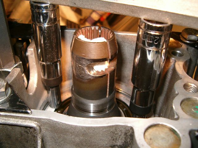
Even though rear clamp is not mounted solidly into flex plate, parts design do not allow more than few mm's fore aft movement for the mounting point. Reason behind this is that torque tube center shaft has a groove few cm's forward from it's rear end. Below picture is from manual gearbox cars shafts front end but automatic's TT design is similar.
Around the perimeter of center the shaft is groove like that so that flex plate clamp bolt can be mounted in any position around 360 degrees. This helps when installing gearbox and TT together as it's not needed to make sure center shaft and flex plate are put in particular position compared to each other.
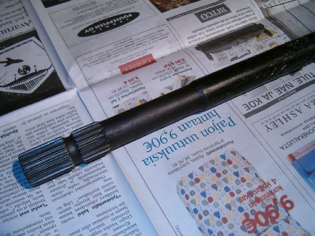
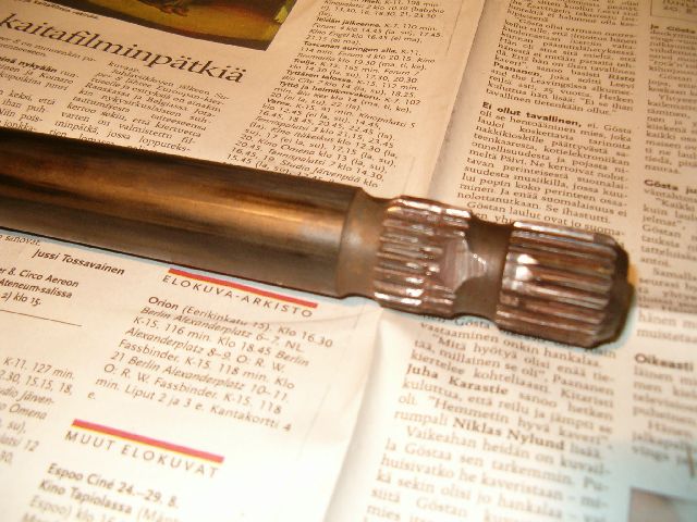
In design version B, flex plates shaft goes around above pictures solid TT center shaft. Center shaft inserts into flex plate some 50 to 60 mm's. Notice horizontal cut about 20 mm's below flex plate pipes top end at below picture.

Cut only allows clamp to be mounted in very narrow "window" within 360 degrees even though it does not matter in what position center shaft is inserted to flex plate pipe.
Flex plate pipes bolt cut must align with center shaft groove in order for clamp bolt to have room to be mounted. This means center shaft can only be inserted into flex plate pipe section certain amount, not much more or less that it. How much fore aft movement for shaft and pipe the clamp allows can be debated. It somewhat depends on if parts are worn or not etc.
Since flex plate has fixed clamp at the front flext plate it probably allows less movement there than what real flex plate has. But movement range on both ends should be much smaller than 10mm absolutely and there is no way it can be 10mm forwards or back from center. This means it's difficult to get that kind of play from clamp at either end. even both clamps together it would be difficult.
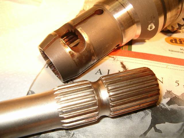
What this means is that large lenght difference needs to come from somewhere else. My bet would be from how torque converter is mounted to gearbox or from how flex plate is mounted to torque converter. Getting above few mm's from either or both flex plate clamps requires taking out metal from either rear flex plate pipe or TT center shaft. Below is example of manual gearbox shafts rear end what has been modified to allow mounting of later style box into early shaft design.
On manual boxes gearbox input shaft was changed during '80 model year when G28.05 box came into use. Clamps position on the input shaft was moved about 10mm forward. Idea was to make lenght of TT center shaft what is inside gearbox input shaft longer. Also on all manual gearboxes, clamp is not welded to input shaft as input shaft bearing needs to be changeable. So design of the parts is similar than automatic version B.
Notice on above picture how much material was removed from one spot to give room for the clamp bolt. It was only done at one are so that it would leave more bores intact. Above cut was needed to gain 10mm different position how deep into gearbox input shaft TT center shaft protrudes. Cut didn't even give all of the 10mm needed as bolt was mounted to extreme side of the movement and it was only barely possible to insert it into clamp. So to gain 10mm cleanly it would require larger portion of the shaft metal removed.
Please do not mix second (leftmost) clean and well done groove in above pic to the modification that was done to the center shaft. Modification is in between two grooves. Leftmost factory done groove is in there only as ending point for the bores on the shaft. It's not used as clamp bolt relief. Reason why manual gearbox center shafts do not have similar narrow groove at front end also is that there needs to be room for double clamp to move rearwards totally on top of shaft when clutch is removed and installed. So front end bores end groove is about 100 mm wide instead of under 10 mm as at rear end.
Below thread has more manual gearbox TT pictures including front end double clamp what is also used in automatic version A.
https://rennlist.com/forums/928-forum/178818-torque-tube-rebuild-pictures-and-tools.html
As mentioned earlier, front flex plate on both A and B versions has clamp welded into bored pipe.
However rear flex plate can not have clamp welded around pipe as two torgue converter front bearings need to be mounted on that shaft and their inner race is smaller than outside diameter of the clamp.
Even though rear clamp is not mounted solidly into flex plate, parts design do not allow more than few mm's fore aft movement for the mounting point. Reason behind this is that torque tube center shaft has a groove few cm's forward from it's rear end. Below picture is from manual gearbox cars shafts front end but automatic's TT design is similar.
Around the perimeter of center the shaft is groove like that so that flex plate clamp bolt can be mounted in any position around 360 degrees. This helps when installing gearbox and TT together as it's not needed to make sure center shaft and flex plate are put in particular position compared to each other.
In design version B, flex plates shaft goes around above pictures solid TT center shaft. Center shaft inserts into flex plate some 50 to 60 mm's. Notice horizontal cut about 20 mm's below flex plate pipes top end at below picture.
Cut only allows clamp to be mounted in very narrow "window" within 360 degrees even though it does not matter in what position center shaft is inserted to flex plate pipe.
Flex plate pipes bolt cut must align with center shaft groove in order for clamp bolt to have room to be mounted. This means center shaft can only be inserted into flex plate pipe section certain amount, not much more or less that it. How much fore aft movement for shaft and pipe the clamp allows can be debated. It somewhat depends on if parts are worn or not etc.
Since flex plate has fixed clamp at the front flext plate it probably allows less movement there than what real flex plate has. But movement range on both ends should be much smaller than 10mm absolutely and there is no way it can be 10mm forwards or back from center. This means it's difficult to get that kind of play from clamp at either end. even both clamps together it would be difficult.
What this means is that large lenght difference needs to come from somewhere else. My bet would be from how torque converter is mounted to gearbox or from how flex plate is mounted to torque converter. Getting above few mm's from either or both flex plate clamps requires taking out metal from either rear flex plate pipe or TT center shaft. Below is example of manual gearbox shafts rear end what has been modified to allow mounting of later style box into early shaft design.
On manual boxes gearbox input shaft was changed during '80 model year when G28.05 box came into use. Clamps position on the input shaft was moved about 10mm forward. Idea was to make lenght of TT center shaft what is inside gearbox input shaft longer. Also on all manual gearboxes, clamp is not welded to input shaft as input shaft bearing needs to be changeable. So design of the parts is similar than automatic version B.
Notice on above picture how much material was removed from one spot to give room for the clamp bolt. It was only done at one are so that it would leave more bores intact. Above cut was needed to gain 10mm different position how deep into gearbox input shaft TT center shaft protrudes. Cut didn't even give all of the 10mm needed as bolt was mounted to extreme side of the movement and it was only barely possible to insert it into clamp. So to gain 10mm cleanly it would require larger portion of the shaft metal removed.
Please do not mix second (leftmost) clean and well done groove in above pic to the modification that was done to the center shaft. Modification is in between two grooves. Leftmost factory done groove is in there only as ending point for the bores on the shaft. It's not used as clamp bolt relief. Reason why manual gearbox center shafts do not have similar narrow groove at front end also is that there needs to be room for double clamp to move rearwards totally on top of shaft when clutch is removed and installed. So front end bores end groove is about 100 mm wide instead of under 10 mm as at rear end.
Below thread has more manual gearbox TT pictures including front end double clamp what is also used in automatic version A.
https://rennlist.com/forums/928-forum/178818-torque-tube-rebuild-pictures-and-tools.html
 09-14-2005, 07:19 PM
#92
Michael,
There is an old quote "When you are up to your �A**E� in alligators, it is difficult to remember that your initial objective was to drain the swamp".
And when you cannot get joy out of what you are trying to do or who you are trying to do it too there is another good saying "May the fleas of a thousand camels infest your underwear".
With that now out of my system lets get down to some business. I have reviewed all the post on your problem and note that we may have led ourselves down the garden path away from what was actually stated by PCM, namely quote:
"The report says: " stripped engine and found thrust face of crankshaft seized. Determined cause due to poor alignment of crankshaft to front shaft therefore putting excessive pressure on rear crankshaft bearing and failing over time."
From this statement there are two definitive reasons given:
1. Found the thrust face of crankshaft seized
2. Determined cause due to poor alignment of crankshaft to front shaft therefore putting excessive pressure on rear crankshaft bearing and failing over time.
I will discuss item 2 first.
PMC stated that the out of alignment was 10mm, is this correct? If the answer is yes then you should be able to confidently say that the out of alignment can be taken as the end of the crankshaft was out of alignment with the forward end of the torque tube drive shaft. Following along with PCM statements then you could assume that the after end of the torque tube drive shaft was in alignment as PCM had reinstalled it that way?
The definition of "alignment" or to "align" something is to 'place - lay in align, bring three or more points into a straight line�. Oxford Dictionary.
I sure the Macquarie, Random House or the Webster�s or any other English dictionary will have similar definitions.
If you accept what PCM have stated: �determined cause due to poor alignment of crankshaft to front shaft therefore putting excessive pressure on rear crankshaft bearing and failing over time�, then from this statement it can be deduced that the drive shaft, being contained with in the torque tube, via it bearings, was axially out-of- alignment with the end of the crankshaft axial alignment by 10mm?
In one of my previous post I questioned this out-of-alignment and mentioned that the deflections of the crankshaft webs caused by 10mm out of alignment would have been excessive and could have led to a crankshaft failure or main bearing failure at the aft end of the engine in a very short time. An out-of-alignment of this magnitude (10mm) can cause crankshaft and bearing failures in engines, that I have worked on and realigned, of up to or even greater than 17,000 kilowatts of horsepower, let alone a small V8 engine with a very stiff crankshaft. In fact I would suggest that if the drive shaft was out-of-alignment with the crankshaft to this magnitude the starter motor may not have been incapable of turning/rotating the crankshaft at all.
I also note from your posts that PCM representatives said that aft crankshaft bearing had failed and the bearing pieces had fallen into the bell housing, hence no bearing pieces were in evidence within the sump when the oil was drained or the sump removed during the work carried out by PCM. You indicated that this work was undertaken by PCM during the period between the transmission repair and the seizure of the engine and PMC showed you a small finger nail size piece that they recovered from inside the bell housing, correct?
Incidentally, I believe from practical experience, that an out of alignment of this magnitude stated would have been impossible to achieve as the torque tube is attached to the forward bell and after bell housings via 12mm set bolts and the alignment appears to be via machined cylindrical inserts sleeves connecting the torque tube faces to the faces of the forward and aft bell housings. As a matter of fact as stated previously in my posts the engine�s crankshaft torque tube, drive shaft, gear box and transaxle are an integral axially aligned unit, so I think it would be reasonable to ask PCM, how could the after end of the crankshaft be out of alignment by 10mm with the forward end of the torque tube drive shaft? And in addition if this out of alignment did exist then you could reasonably ask how could the engine have been cranked let alone run with this misalignment�?
PCM representatives also stated that the thrust face of the crankshaft was seized, item 1 above.
This would indicate excessive forward axial load on the crankshaft either from existing pre-load plus migration forward of the forward flexplate clamp or from the possible incorrect installation of the automatic transmission with torque converter and the possible reconnection of the aft flexplate clamp to the after end of the torque tube drive shaft assembly applying forward pressure on the crankshaft?
I don�t believe that an axial out of alignment as stated above would in itself put forward pressure on the thrust bearing by the crankshaft causing the seizure of the crankshaft thrust face. If this amount of out of alignment did in fact occur it would have possibly reduced the forward loading on the thrust bearing, marginally (triangulation effect). This is only my assertion and or belief.
Did PCM state or indicate that the crankshaft thrust face had worn into the main bearing housing of the crankcase, or was it just seized to the main bearing thrust face, remembering that the thrust bearing is around the middle of the crankshaft and not located at the after crankshaft bearing?
Again from your posts you indicate that the engine was repaired by PCM. From previous threads within this forum, if the crankshaft thrust collar wears through the crankcase main thrust bearing it damages the crankcase to an extent that it is un-repairable and requires a short motor to be fitted.
Did PCM report what actually happened that ran up a bill of $25,000.00? I believe you would be quite justified to have this fully itemized out into what was found or failed together with parts and labour consumed in the repair. Of course you brief should request/obtain this within the claimants �proof of evidence� or �discovery phase� of the litigation.
If there was no forward thrust on the crankshaft imparted by PCM�s technicians, as they claim, as the automatic gearbox was reinstalled as it was taken apart from the after end of the drive shaft and torque tube, then how could the thrust face of the crankshaft come to be seized? I believe there are conflicting statement being made here!
PCM have implied that this failure of the after crankshaft bearing came about from previous engine work done by a third party, correct?
How long had you had the car been back under PCM care before you took it to them to check the automatic transmission, one, two or more years?
This is an important question as I feel sure that an engineering expert could calculate the out of alignment forces imposed on the crankshaft, the frictional load between the aft bearing and the crankcase journal, the bending moment on the crankshaft over this bearing surface with the possibility of torsional fatigue failure of the crankshaft over time and the out of alignment forces imposed on the forward flexplate. If the engine could have started I believe it only run for a short time and the onset of a failure would have been very rapid.
I would also believe that an expert (like the type mentioned above) should be able to calculate whether the starter motor torque could have been sufficient to overcome the frictional resistance due to the out-of-alignment crankshaft and torque tube drive shaft.
The outcome of these questions/investions posed here may turn out to be an engineering impossibility as to the cause of failure stated by PCM.
If in fact the aft main bearing had failed in the manner described by PCM and the debris had fallen into the bell housing then there should be damage to the crankshaft, such as thermal cracking of the crankshaft main bearing journal in way of the aft bearing due to the heating up of the crankshaft bearing surface during rotation and it subsequent quenching by the lubricating oil. I have experienced this in large diesel engines and after this type of failure the crankshaft either needs replacing or machining of the damaged crankshaft journal bearing to an undersize minimum diameter specified by the engine manufacturer, thereby ensuring its residual strength is capable of transmitting the maximum torque load.
At this stage of the argument it now hinges on what PCM did during its repair of the engine to rectify the seizure of what ever happened. I they stated that the crankshaft was reused and the crankcase remained serviceable, that is it was not damaged or it was repaired, then this should be able to be verified by removing the crankshaft and having it examined by the expert to ascertain whether it is still the existing crankshaft, or whether it has been machined or weather it has been renewed. I would also pursue the aspect of the crankshaft thrust seizure to determine whether the thrust collar was scored, worn, thermally cracked or whether there are seizure marks on the after horizontal faces of the crankcase thrust bearing pocket so as to determine the extend of seizure and damage.
In closing this post I think that PCM have made an incorrect report as to the reason of the failure and these inconstancies should be vigorously pursued as I believe that what they have stated maybe an engineering impossibility.
You can now see the reason for my statement regarding the alligators as we have been chasing the forward loading of the thrust bearing (which may have actually been the cause of the failure) instead of looking at what was actually reported by PCM. If this is the case I can clearly see a reason that you may wish someone discomfort via fleas.
I fully appreciate this is a very long and involved post done late at night, so if there is any clarification or disjointedness please accept the circumstance under which it was written.
Tails 1990 928 S4 Auto
09-21-2005, 11:50 PM
#93
Intermediate
Thread Starter

Join Date: Aug 2005
Location: MELBOURNE
Posts: 28
Likes: 0
Received 0 Likes
on
0 Posts
Hi Erkka, Tails, All
[QUOTE=Vilhuer]Hi Michael,
I absolutely agree with you Erkka in the above post.
Question : When you say a few mm is this guess or can the bolt move only that much in the groove or is there no more spline?
The rear clamp is not welded so is there only one bolt ( clamping the drive shaft ) or is there another bolt holding the torgue shaft as well?
I am still trying to get hold of this rear flex / clamp.
Regards
Michael
[QUOTE=Vilhuer]Hi Michael,
In design version B, flex plates shaft goes around above pictures solid TT center shaft. Center shaft inserts into flex plate some 50 to 60 mm's. Notice horizontal cut about 20 mm's below flex plate pipes top end at below picture.
Cut only allows clamp to be mounted in very narrow "window" within 360 degrees even though it does not matter in what position center shaft is inserted to flex plate pipe.
Flex plate pipes bolt cut must align with center shaft groove in order for clamp bolt to have room to be mounted. This means center shaft can only be inserted into flex plate pipe section certain amount, not much more or less that it. How much fore aft movement for shaft and pipe the clamp allows can be debated. It somewhat depends on if parts are worn or not etc.
I absolutely agree with you Erkka in the above post.
Question : When you say a few mm is this guess or can the bolt move only that much in the groove or is there no more spline?
The rear clamp is not welded so is there only one bolt ( clamping the drive shaft ) or is there another bolt holding the torgue shaft as well?
I am still trying to get hold of this rear flex / clamp.
Regards
Michael
09-22-2005, 07:56 AM
#94
Addict
Rennlist Member
Rennlist Member
Hi Michael,
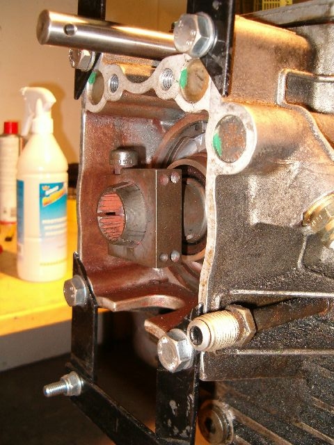
Let see if this clears up who those parts go together. Diagram is of '87+ manual gearbox cars clutch. Hope this isn't too confusing. Only pay attention to stuff around ellipse B and disrecard all the rest including blue A, X and Y.

In automatic gearbox TT system, similar parts are:
C = clamp
D = clamp bolt
E = TT center shaft
F = Flex plate shaft (pipe)
C and D are same as manual gearbox parts in this picture:
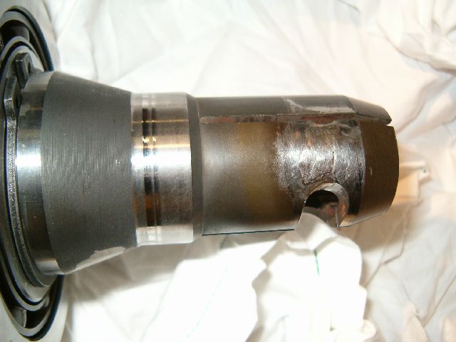
E is same as this:
Except bores and groove should look better, like this:
F is this:
F has bolt groove and three longitudinal cuts like this manual gearbox input shaft:
Longitudinal cuts are there to allow pipe (F) tighten around TT center shaft (E) when clamp bolt (D) is tightened. Clamp (C) spreads tightening force uniformly around flex plate shaft (F).
There is only one clamp (C) and one clamp bolt (D) at TT rear end.
On diagram, notice how center shaft (E) and two grooves pictured and bolt (D) is only on lower one. Two grooves describe 360 degrees all around shaft groove in real life. Also notice how little extra room there is in groove compared to diameter of the bolt (D). Even though there is little play in there above diagram is accurate in describing movement range as minimal.
As mentioned earlier, center shaft (E) must be inside flex plate pipe (F) just enough (no more, no less) to the groove to align correctly for bolt (D). If not, there is not a chance for bolt (D to) go through the groove in center shaft (E). How large is area where bolt (D) can go through depends on how worn parts are. When bolt (D) is loose it can make more room for itself by wearing center shaft (E) groove and/or flex plate pipe (F) cut larger. If all parts are like they left from factory, area where center shaft (E) groove and flex plate pipe (F) cut align properly has only few mm's fore/aft play. 'Few' meaning clearly smaller than 5mm. Especially in only one direction if we think there is equal play towards fore and aft. Factory allows only 1mm (+/- 0.5mm) measuring difference for TT center shaft to mounting flange relationship.
https://rennlist.com/forums/928-forum/178818-torque-tube-rebuild-pictures-and-tools.html#post2006537
So bolt (D) has very limited fore/aft position where it can reside. If center shaft (E) and flex plate pipe (F) do not align perfectly this small fore/aft place gets even smaller or non existent. In your case I would concentrate more to what was done to torque converter and could it have caused flex plate pipe (F) to be positioned more forward compared to torque converter housing front mounting surface. If flex plate pipe (F) is not positioned correctly compated to center shaft it will cause preload to the system when center shaft (E) and flex plate pipe (F) are bolted together.
If workshop somehow messed up putting gearbox back together and managed to put flex plate pipe (F) in wrong (too forward) position this would be by far the easiest explanation what went wrong. Someone with S4 or GTS automatic gearbox stuff on the table could maybe provide some clues how this is possible. Wrong width bearings into flex plate carrier for example? I'm not sure what possibilities there are and can't remember exacly what was done to the gearbox.
Hope this clears up further what kind of system it is.
Let see if this clears up who those parts go together. Diagram is of '87+ manual gearbox cars clutch. Hope this isn't too confusing. Only pay attention to stuff around ellipse B and disrecard all the rest including blue A, X and Y.
In automatic gearbox TT system, similar parts are:
C = clamp
D = clamp bolt
E = TT center shaft
F = Flex plate shaft (pipe)
C and D are same as manual gearbox parts in this picture:
E is same as this:
Except bores and groove should look better, like this:
F is this:
F has bolt groove and three longitudinal cuts like this manual gearbox input shaft:
Longitudinal cuts are there to allow pipe (F) tighten around TT center shaft (E) when clamp bolt (D) is tightened. Clamp (C) spreads tightening force uniformly around flex plate shaft (F).
There is only one clamp (C) and one clamp bolt (D) at TT rear end.
On diagram, notice how center shaft (E) and two grooves pictured and bolt (D) is only on lower one. Two grooves describe 360 degrees all around shaft groove in real life. Also notice how little extra room there is in groove compared to diameter of the bolt (D). Even though there is little play in there above diagram is accurate in describing movement range as minimal.
As mentioned earlier, center shaft (E) must be inside flex plate pipe (F) just enough (no more, no less) to the groove to align correctly for bolt (D). If not, there is not a chance for bolt (D to) go through the groove in center shaft (E). How large is area where bolt (D) can go through depends on how worn parts are. When bolt (D) is loose it can make more room for itself by wearing center shaft (E) groove and/or flex plate pipe (F) cut larger. If all parts are like they left from factory, area where center shaft (E) groove and flex plate pipe (F) cut align properly has only few mm's fore/aft play. 'Few' meaning clearly smaller than 5mm. Especially in only one direction if we think there is equal play towards fore and aft. Factory allows only 1mm (+/- 0.5mm) measuring difference for TT center shaft to mounting flange relationship.
https://rennlist.com/forums/928-forum/178818-torque-tube-rebuild-pictures-and-tools.html#post2006537
So bolt (D) has very limited fore/aft position where it can reside. If center shaft (E) and flex plate pipe (F) do not align perfectly this small fore/aft place gets even smaller or non existent. In your case I would concentrate more to what was done to torque converter and could it have caused flex plate pipe (F) to be positioned more forward compared to torque converter housing front mounting surface. If flex plate pipe (F) is not positioned correctly compated to center shaft it will cause preload to the system when center shaft (E) and flex plate pipe (F) are bolted together.
If workshop somehow messed up putting gearbox back together and managed to put flex plate pipe (F) in wrong (too forward) position this would be by far the easiest explanation what went wrong. Someone with S4 or GTS automatic gearbox stuff on the table could maybe provide some clues how this is possible. Wrong width bearings into flex plate carrier for example? I'm not sure what possibilities there are and can't remember exacly what was done to the gearbox.
Hope this clears up further what kind of system it is.
09-22-2005, 08:10 AM
#95
Intermediate
Thread Starter
Join Date: Aug 2005
Location: MELBOURNE
Posts: 28
Likes: 0
Received 0 Likes
on
0 Posts
Tails, All
"The report says: " stripped engine and found thrust face of crankshaft seized. Determined cause due to poor alignment of crankshaft to front shaft therefore putting excessive pressure on rear crankshaft bearing and failing over time."
..PCM stated that the out of alignment was 10mm, is this correct?
Following along with PCM statements then you could assume that the after end of the torque tube drive shaft was in alignment as PCM had reinstalled it that way?
Who can argue with them? They've got the best guys in this town. They work on these cars more than anyone. Right?
The definition of "alignment" or to "align" something is to 'place - lay in align, bring three or more points into a straight line�. Oxford Dictionary.
What's a web?
In this thread we have discussed at length the issue of the WSM's clarity and intentions. Should we expect different from P--?
Who knows? Perhaps their definition of alignment is something else. Or perhaps it isn't.
Rear crankshaft bearing? Perhaps they mean thrust bearing. Maybe they'll make up their mind later. Aren't they allowed to?
Since they have refused to talk to me I'm afraid I do not know their intentions.
No, the sump work was done 6 months prior to the transmission work.
The small piece was the thrust bearing. It was recovered after stripping the engine. Other bearings were intact.
Someone said, in order to beat your opponent you confuse him.
Remember, the thrust bearing had virtually disintegrated and only a small bit was what's left to show.
Twenty five kg of superglue? Liquid Metal? Labour Cost? Profit?
You sound to me like an engineer. Methodical thinking.
Two and a half years.
Is there punishment for that? Prize?
You can now see the reason for my statement regarding the alligators as we have been chasing the forward loading of the thrust bearing (which may have actually been the cause of the failure) instead of looking at what was actually reported by PCM. If this is the case I can clearly see a reason that you may wish someone discomfort via fleas.
I wish more than fleas.
I fully understand and follow your agrguments. Would you like to argue this for me in the box? (I've sent you a mail. My second.)
Tails 1990 928 S4 Auto
Regards
Michael sick1989 928 S4 Auto very sick
Originally Posted by Tails
"The report says: " stripped engine and found thrust face of crankshaft seized. Determined cause due to poor alignment of crankshaft to front shaft therefore putting excessive pressure on rear crankshaft bearing and failing over time."
..PCM stated that the out of alignment was 10mm, is this correct?
Following along with PCM statements then you could assume that the after end of the torque tube drive shaft was in alignment as PCM had reinstalled it that way?
The definition of "alignment" or to "align" something is to 'place - lay in align, bring three or more points into a straight line�. Oxford Dictionary.
If you accept what PCM have stated: � due to poor alignment of crankshaft to front shaft therefore putting excessive pressure on rear crankshaft bearing and failing over time�, from this statement it can be deduced that the drive shaft, being contained with in the torque tube, via it bearings, was axially out-of- alignment with the end of the crankshaft axial alignment by 10mm?
In one of my previous post I questioned this out-of-alignment and mentioned that the deflections of the crankshaft webs caused by 10mm out of alignment would have been excessive and could have led to a crankshaft failure or main bearing failure at the aft end of the engine in a very short time.
In one of my previous post I questioned this out-of-alignment and mentioned that the deflections of the crankshaft webs caused by 10mm out of alignment would have been excessive and could have led to a crankshaft failure or main bearing failure at the aft end of the engine in a very short time.
An out-of-alignment of this magnitude (10mm) can cause crankshaft and bearing failures in engines, that I have worked on and realigned, of up to or even greater than 17,000 kilowatts of horsepower, let alone a small V8 engine with a very stiff crankshaft. In fact I would suggest that if the drive shaft was out-of-alignment with the crankshaft to this magnitude the starter motor may not have been incapable of turning/rotating the crankshaft at all.
In this thread we have discussed at length the issue of the WSM's clarity and intentions. Should we expect different from P--?
Who knows? Perhaps their definition of alignment is something else. Or perhaps it isn't.
Rear crankshaft bearing? Perhaps they mean thrust bearing. Maybe they'll make up their mind later. Aren't they allowed to?
Since they have refused to talk to me I'm afraid I do not know their intentions.
I also note from your posts that PCM representatives said that aft crankshaft bearing had failed and the bearing pieces had fallen into the bell housing, hence no bearing pieces were in evidence within the sump when the oil was drained or the sump removed during the work carried out by PCM. You indicated that this work was undertaken by PCM during the period between the transmission repair and the seizure of the engine and PMC showed you a small finger nail size piece that they recovered from inside the bell housing, correct?
The small piece was the thrust bearing. It was recovered after stripping the engine. Other bearings were intact.
Incidentally, I believe from practical experience, that an out of alignment of this magnitude stated would have been impossible to achieve as the torque tube is attached to the forward bell and after bell housings via 12mm set bolts and the alignment appears to be via machined cylindrical inserts sleeves connecting the torque tube faces to the faces of the forward and aft bell housings. As a matter of fact as stated previously in my posts the engine�s crankshaft torque tube, drive shaft, gear box and transaxle are an integral axially aligned unit, so I think it would be reasonable to ask PCM, how could the after end of the crankshaft be out of alignment by 10mm with the forward end of the torque tube drive shaft? And in addition if this out of alignment did exist then you could reasonably ask how could the engine have been cranked let alone run with this misalignment�?
PCM representatives also stated that the thrust face of the crankshaft was seized, item 1 above.
This would indicate excessive forward axial load on the crankshaft either from existing pre-load plus migration forward of the forward flexplate clamp or from the possible incorrect installation of the automatic transmission with torque converter and the possible reconnection of the aft flexplate clamp to the after end of the torque tube drive shaft assembly applying forward pressure on the crankshaft?
I don�t believe that an axial out of alignment as stated above would in itself put forward pressure on the thrust bearing by the crankshaft causing the seizure of the crankshaft thrust face. If this amount of out of alignment did in fact occur it would have possibly reduced the forward loading on the thrust bearing, marginally (triangulation effect). This is only my assertion and or belief.
Did PCM state or indicate that the crankshaft thrust face had worn into the main bearing housing of the crankcase, or was it just seized to the main bearing thrust face, remembering that the thrust bearing is around the middle of the crankshaft and not located at the after crankshaft bearing?
Again from your posts you indicate that the engine was repaired by PCM. From previous threads within this forum, if the crankshaft thrust collar wears through the crankcase main thrust bearing it damages the crankcase to an extent that it is un-repairable and requires a short motor to be fitted.
Did PCM report what actually happened that ran up a bill of $25,000.00? I believe you would be quite justified to have this fully itemized out into what was found or failed together with parts and labour consumed in the repair.
Did PCM report what actually happened that ran up a bill of $25,000.00? I believe you would be quite justified to have this fully itemized out into what was found or failed together with parts and labour consumed in the repair.
Of course you brief should request/obtain this within the claimants �proof of evidence� or �discovery phase� of the litigation.
If there was no forward thrust on the crankshaft imparted by PCM�s technicians, as they claim, as the automatic gearbox was reinstalled as it was taken apart from the after end of the drive shaft and torque tube, then how could the thrust face of the crankshaft come to be seized? I believe there are conflicting statement being made here!
If there was no forward thrust on the crankshaft imparted by PCM�s technicians, as they claim, as the automatic gearbox was reinstalled as it was taken apart from the after end of the drive shaft and torque tube, then how could the thrust face of the crankshaft come to be seized? I believe there are conflicting statement being made here!
PCM have implied that this failure of the after crankshaft bearing came about from previous engine work done by a third party, correct? How long had you had the car been back under PCM care before you took it to them to check the automatic transmission, one, two or more years?
This is an important question as I feel sure that an engineering expert could calculate the out of alignment forces imposed on the crankshaft, the frictional load between the aft bearing and the crankcase journal, the bending moment on the crankshaft over this bearing surface with the possibility of torsional fatigue failure of the crankshaft over time and the out of alignment forces imposed on the forward flexplate. If the engine could have started I believe it only run for a short time and the onset of a failure would have been very rapid.
I would also believe that an expert (like the type mentioned above) should be able to calculate whether the starter motor torque could have been sufficient to overcome the frictional resistance due to the out-of-alignment crankshaft and torque tube drive shaft.
The outcome of these questions/investions posed here may turn out to be an engineering impossibility as to the cause of failure stated by PCM.In closing this post I think that PCM have made an incorrect report as to the reason of the failure and these inconstancies should be vigorously pursued as I believe that what they have stated maybe an engineering impossibility.
You can now see the reason for my statement regarding the alligators as we have been chasing the forward loading of the thrust bearing (which may have actually been the cause of the failure) instead of looking at what was actually reported by PCM. If this is the case I can clearly see a reason that you may wish someone discomfort via fleas.
I wish more than fleas.
.....involved post done late at night, so if there is any clarification or disjointedness please accept the circumstance under which it was written.
Tails 1990 928 S4 Auto
Michael sick1989 928 S4 Auto very sick
09-22-2005, 09:12 AM
#96
Addict
Rennlist Member
Rennlist Member
Crankshaft can not move 10mm forward. It will seize long before that. Several mm's before it all eight pistons for example would be fighting against this even though there is some play in connecting rods upper end.
09-22-2005, 10:11 PM
#97
Rennlist Member
Victim, 'web' in this context is a supporting part of a sstructure, eg on a crankshaft, the pieces that connect two bearing journals (where the rods connect, or the main bearing) are call webs, or crank webs; also the part of the crankcase casting above the bearing hole can be a 'web'.
Looking at all the above discussion about 'alignment', I think we have gone down a dead end due to poor terminology - I doubt that PCM meant alignment in engineering terms, as in axially lined up, collinear, but more likely they meant incorrectly adjusted as to lengths of engagement of the couplings when the clamps were tightened.
FWIW a man I have some respect for in this area tells me his practice after this type of work is to leave the clamp bolts loose, run the engine, and do several short drives around the block to ensure everything is settled, a couple of heat cycles, no loading of couplings, before tightening the clamps.
jp 83 Euro S AT 49k
09-25-2005, 07:55 AM
#98
Intermediate
Thread Starter
Join Date: Aug 2005
Location: MELBOURNE
Posts: 28
Likes: 0
Received 0 Likes
on
0 Posts
Originally Posted by Vilhuer
Crankshaft can not move 10mm forward. It will seize long before that. Several mm's before it all eight pistons for example would be fighting against this even though there is some play in connecting rods upper end.
You mean DRIVE shaft Or FLEXPLATE.
( Recommended Crankshaft play is 0.4 mm Max.)
Erkka I am still looking for a front flex plate. You have mentioned previously said there is only millimetres of room to position this flex plate clamp on to the drive shaft spline. What limits this "window"? Do you have a schematic drawing? eg like 39-141.
If you look at 39-141 and remove the shims and circlips whats stops the clamp sliding forward ( i.e. forward preload ) OR backward on the spline?
Regards
Michael
09-25-2005, 08:02 AM
#99
Intermediate
Thread Starter
Join Date: Aug 2005
Location: MELBOURNE
Posts: 28
Likes: 0
Received 0 Likes
on
0 Posts
Hi All
Thanks jpitman2
Why don't they just leave it unclamped?
Regards
Michael
Originally Posted by jpitman2
Victim, 'web' in this context is a supporting part of a sstructure, eg on a crankshaft, the pieces that connect two bearing journals (where the rods connect, or the main bearing) are call webs, or crank webs; also the part of the crankcase casting above the bearing hole can be a 'web'.
FWIW a man I have some respect for in this area tells me his practice after this type of work is to leave the clamp bolts loose, run the engine, and do several short drives around the block to ensure everything is settled, a couple of heat cycles, no loading of couplings, before tightening the clamps.
jp 83 Euro S AT 49k
jp 83 Euro S AT 49k
Regards
Michael
09-25-2005, 09:40 AM
#100
When are you intending on getting your car back on the road? Wish you luck in your legal battles, but please don't let it eat you up.
Last edited by slate blue; 09-26-2005 at 05:28 AM.
09-25-2005, 10:33 AM
#101
Addict
Rennlist Member
Rennlist Member
Originally Posted by victim
You mean DRIVE shaft Or FLEXPLATE.
( Recommended Crankshaft play is 0.4 mm Max.)
( Recommended Crankshaft play is 0.4 mm Max.)
Erkka I am still looking for a front flex plate. You have mentioned previously said there is only millimetres of room to position this flex plate clamp on to the drive shaft spline. What limits this "window"? Do you have a schematic drawing? eg like 39-141.
https://rennlist.com/forums/928-forum/228734-failed-torque-converter-bearings-or-why-do-we-have-these-flex-plate-issues.html
I can't remember seeing other diagrams than what Schocki posted. My earlier statement about mm's comes from fact that flex plate will resist effort to bolt front clamp in wrong position. If plate is mounted to flywheel it will only allow clamp to be mounted in very short area of the center shaft without forcing plate to position.
As it is meantioned before in this thread it would be possible to get plate mounted wrongly by tightening center clamp before TT is mounted to bellhousing. This would obviously create pressure to crank and I believe this is workshops view what went wrong. And they also say front plate was mounted wrongly long before they stated gearbox removal.
If above is the case and front plate was 10mm or more wrong it should have in my opinion pushed center shaft back towards gearbox to releave excess pressure from the flex plate. It doesn't take that much pressure to push TT center shaft towards rear. I believe center shaft would not have stayed put when gearbox was out. Techs should have seen misalignment of center shaft when putting gearbox back to car. And they should have measured center shaft protrusion when gearbox was out.
I was in garage yesterday cleaning gearbox parts and quickly took these pictures of clutch shaft and 5sp box input shaft to illustrate how small window is at rear plate clamp.

If you look at 39-141 and remove the shims and circlips whats stops the clamp sliding forward ( i.e. forward preload ) OR backward on the spline?
Too bad I do not have access to '87 S4 flont plate anymore as it was sold little before you started this thread. But having seen it then, bores in that clamp are not very long. They are strong enough to fight against 4mm misalignment pressure as reported by listers but are they strong enough to withstand 10mm. Front clamp is obviously moving as TBF problem exists at all but I believe 10mm is so much that front plate would have pushed center shaft towards rear and caused damage in torque converter area also. That is if front plate could even stay in one piece. Which I find very hard to believe.
Above mentioned front plate was sold to '84 S owner as spare to rear plate since original had cracked flat plate. And there wasn't even any movement in TT center shaft. He installed rear clamp to this flat triangle to make it work at rear.
09-25-2005, 10:42 AM
#102
Addict
Rennlist Member
Rennlist Member
Originally Posted by victim
Why don't they just leave it unclamped?
09-26-2005, 12:03 PM
#103
Intermediate
Thread Starter
Join Date: Aug 2005
Location: MELBOURNE
Posts: 28
Likes: 0
Received 0 Likes
on
0 Posts
Originally Posted by Vilhuer
I meant crankshaft. I'm not sure what measurement exactly they mean when they mention 10mm. Made that statement just to illustrate it's virtually impossible for crank to move 10mm forward. Almost everything rotating in engine will resist so large movement and entire engine would "explode" before such misalignment could be reached..
Just a quick note to say that the 10 mm was supposed to be what the front flex plate was loaded or tensioned. They would probably like all of the 10 mm to be from the front clamp since they said a third party had incorrectly done it from the engine side.
Cheers