When you click on links to various merchants on this site and make a purchase, this can result in this site earning a commission. Affiliate programs and affiliations include, but are not limited to, the eBay Partner Network.
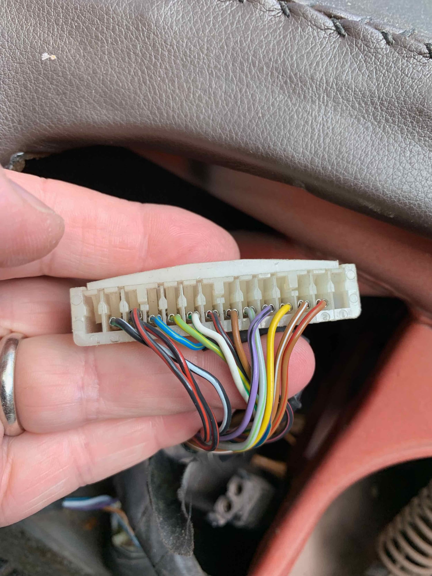
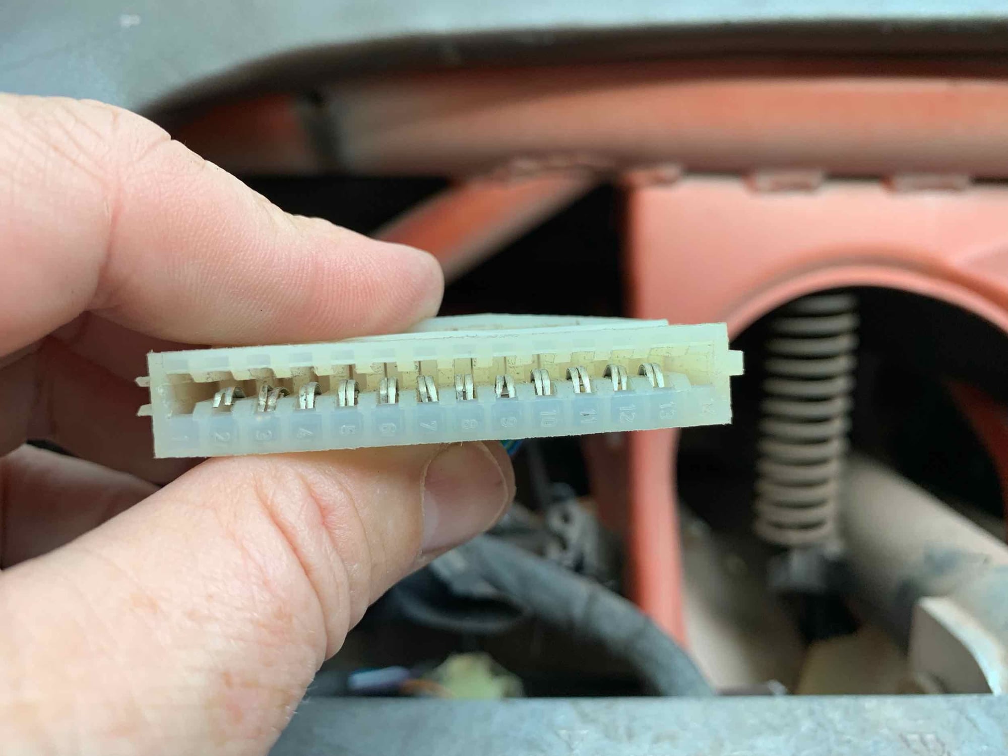
I am working through gauge issues and have found some potential concerns in pins inside the AMP 925499 14 pin connectors that mate to the cluster itself.
the back of these either flip up or somehow slide out I am assuming to reveal/remove individual pins.
anyone know how to make this work? One of mine even has a little plastic clip that looks to hold everything together.
there are three little indentions that may or may not be related to the release of the pins.
Scott,
I had issues with my pod connectors after cleaning the contacts, and was advised that the blades inside the hood are very soft and easy to bend so they fail to connect. I used a piece like a dental pick (pointed fine wire with a right angle near the tip) to get behind the blades and bend them towards the centre to retension them - worked fine. Symptom was gauges moving when something unrelated was turned on - eg fuel level or temp gauge rising when turning lights on, due to a failure of a ground connection. Note there are multiple ground connectors on the R connector.
jp 83 Euro S AT 57k
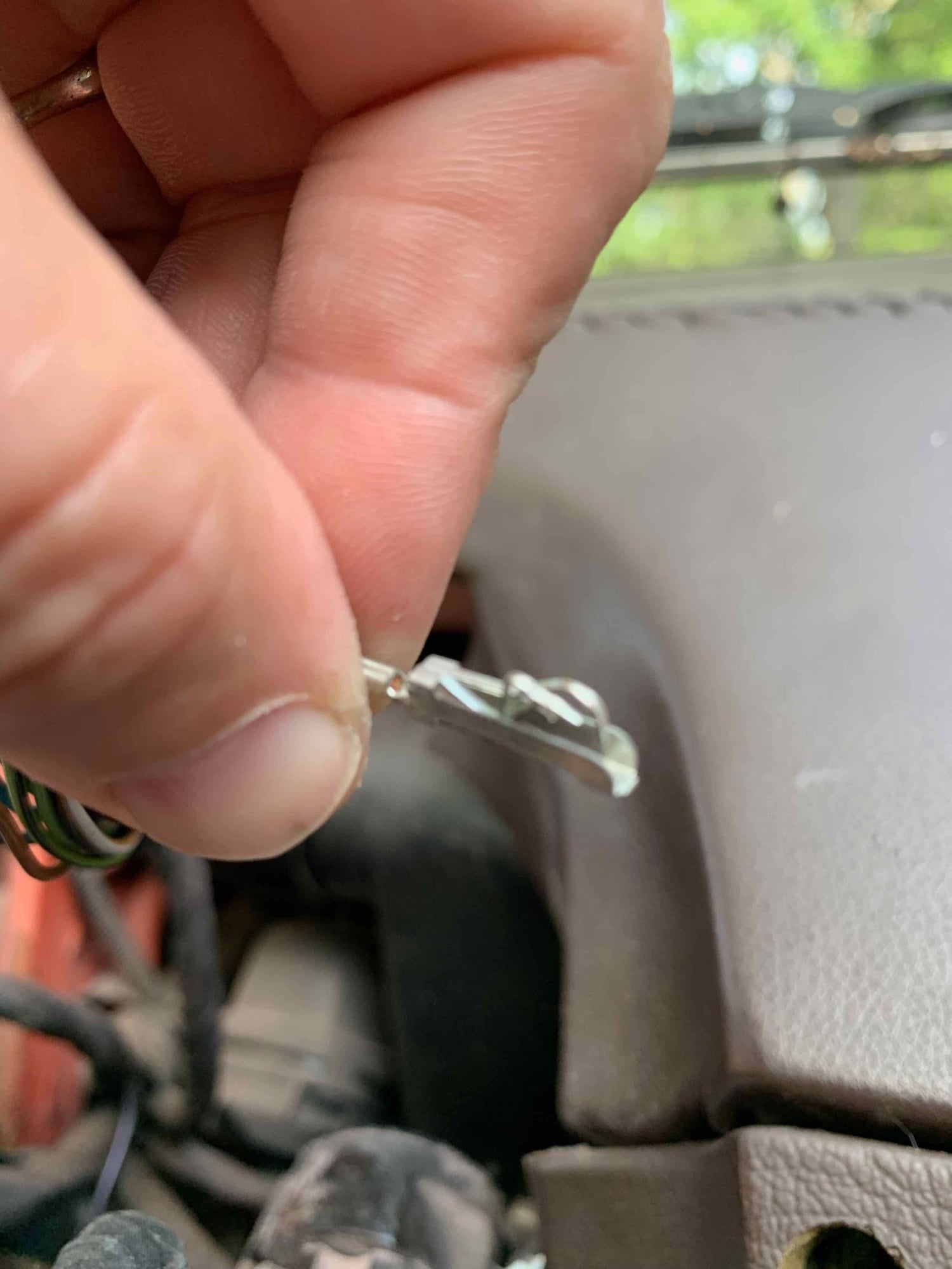
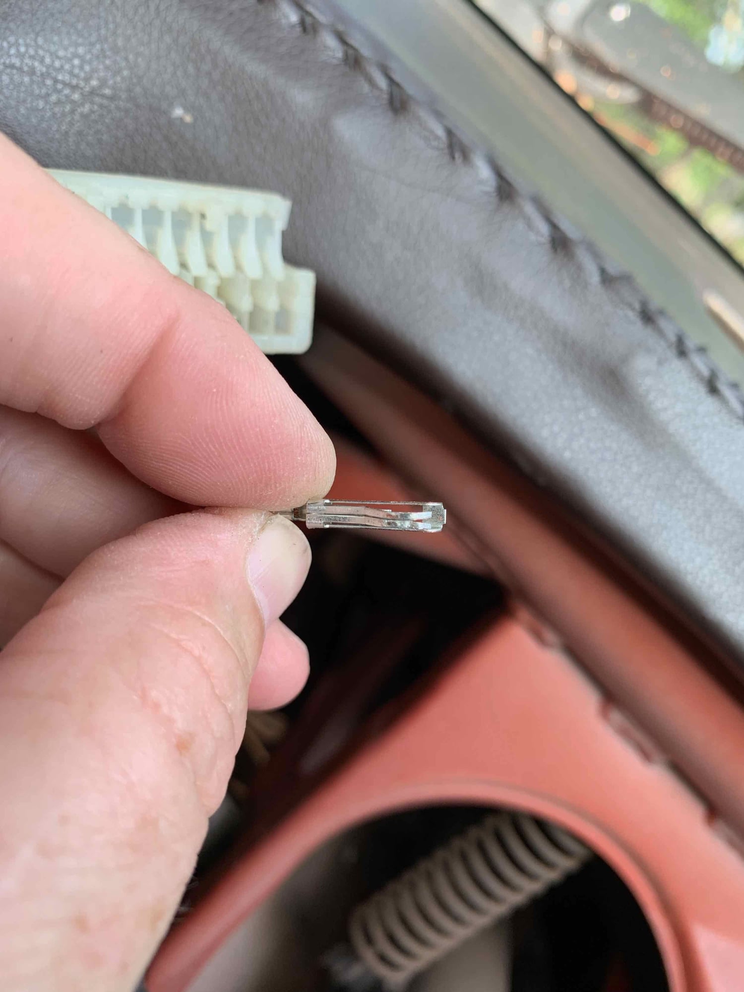
I have a couple of pins in there that are beyond being able to pull with a pick (tried that). I was able to straighten a couple out, but at this point I need to pull the remaining bent pins out to bend them back to shape. They have been 'pushed back' axially into the back of the connector (think what happens to the front of a car's crumple zones in a head-on collision).
There has got to be a way to either a) release the pin so it slides out the back, or b) pull that back part of the connector off so that I can slide the pin out. Just can't get it to work. Tyco (who now owns AMP) shows a listing for the connector itself but has no information other than listing it as 'obsolete'. No pictures or anything.
I'll keep this thread updated if I learn anything...there has to be a way.
Its an AMP 925499. On the 1983 it is a 14 pin connector (there are 3 of them on the early clusters). The connectors are also found on period VWs and Audi's.
I may be onto a solution and will keep this thread updated. It would be good to know if we can still get replacement pins from somewhere.
I knew there had to be a way...!!! This may help all of us with bent pins. This is from an early 80's VW vanagon gauge cluster replacement but connectors appear to be the same. Skip ahead to 6'50"...
I will try to get to mine tonight and report back.
I dont remember the connector looking like that one, but its been a while since I was in there. Makes sense that it has to open something like that, as the contacts are not push-in types retained by tangs.
jp 83 Euro S AT 57k
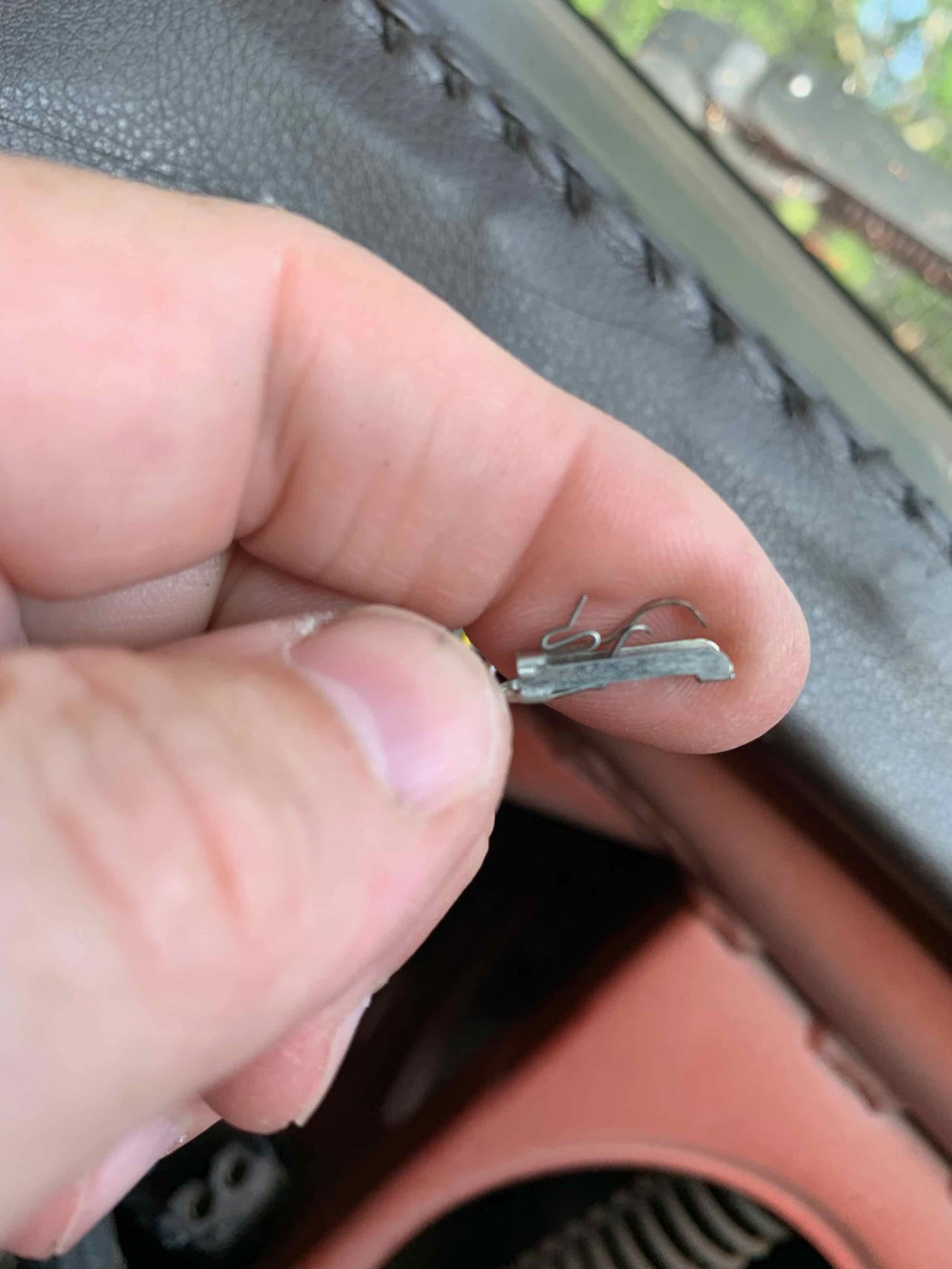
I hope this will help someone down the road. The pins are not as delicate as they seem when trying to adjust them still in the connector housing. It is so easy to get them out I would encourage the recommended process to change to removing the pins to adjust them.
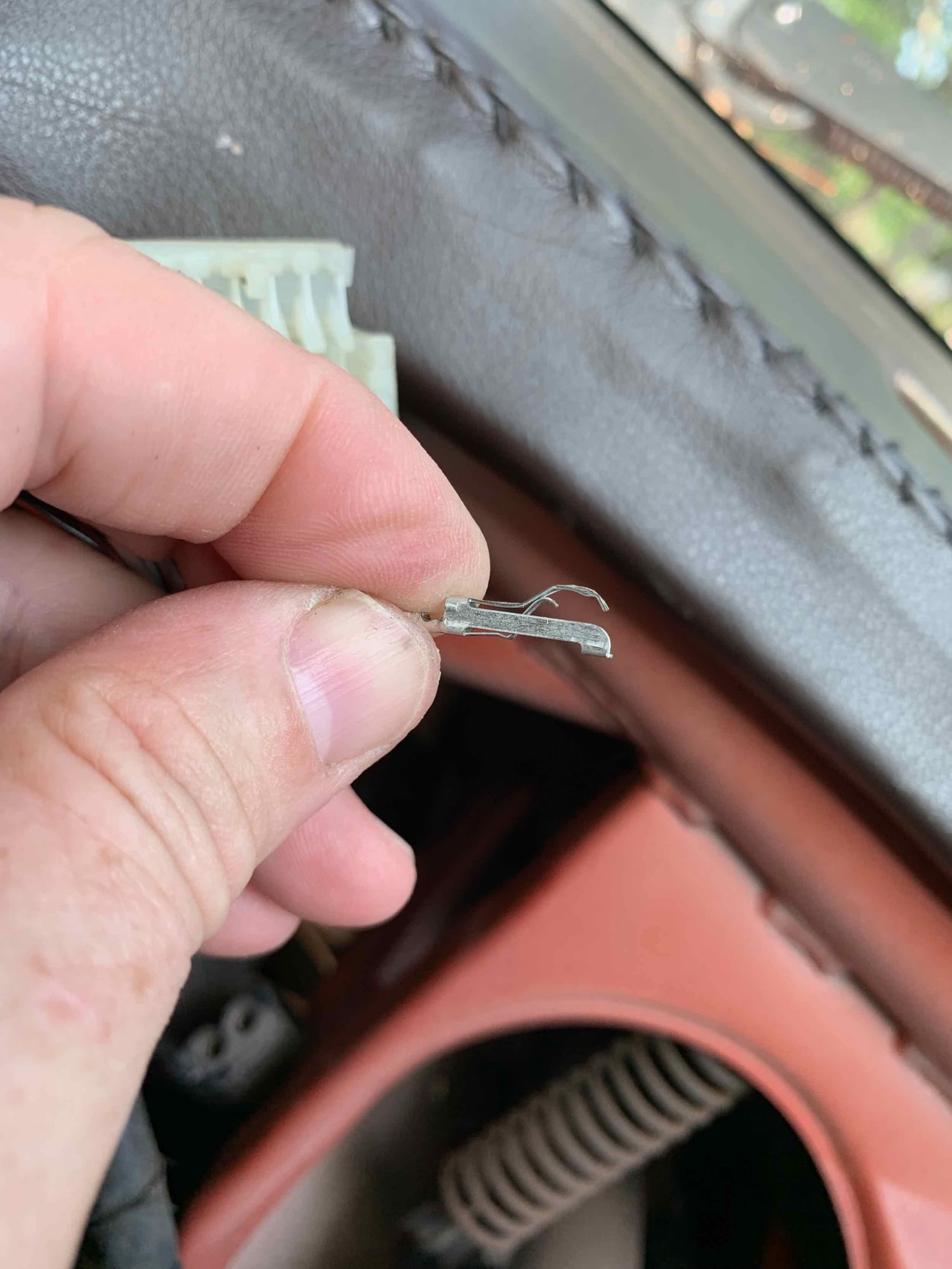
Left connector (missing the little factory clip that holds the back in place). Back of the connector opened up. Just pull up on it - took more strength than I anticipated. One of my fubar'd pins. The left side was 'pushed back' by the edge of the circuit board/hard plastic under the foil. I had 5 or 6 pins like this. I believe the other side of the split was probably making contact (e.g. I did not have any where both sides were pushed back), but both sides making contact will make a better connection. Grabbed the front of the pushed back end and pulled straight forward with the tip of needlenose pliers - don't try to recreate the bend yet. The natural manufacturing process keeps some of the bend in there. Now use the needlenose pliers to recreate the curve in the split side to match the side that was not messed up. I could not get exact, but it is certainly better than it was. Top view. Reinstalled. Not perfect, but in light of the fact that we can't get replacement pins, better than it was. Will have to be careful reassembling everything.
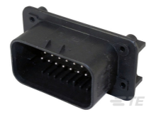
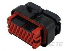
Wow, that's a heckuva set up! So is it time to start finding a replacement modern connector to retrofit, since the pins are NLA?
I just bought a Tyco Ampseal 23-pin connector set to retrofit my '78 cluster, but they make larger and smaller ones depending on the customer's requirements.
The pins are 7-12 cents each, depending on whether you want them tin or gold plated.

 06-23-2019, 09:07 PM