When you click on links to various merchants on this site and make a purchase, this can result in this site earning a commission. Affiliate programs and affiliations include, but are not limited to, the eBay Partner Network.
My in-tank fuel pump had a split hose and a broken wire, so I replaced it with an earlier type strainer but missed the memo that recommended also using a pre '89 fuel pump with a strainer.....
Anyway, I would like to repair the pump and replace it in the car, so after a couple of hours of diligent searching and reorganization in the garage, I have rediscovered the pump and have started the resurrection process.
FWIW, the pump seems to work: it pumps, is quiet, and draws about 1.5 amps at 12 volts; but before I call Roger for parts and Greg's refurbish kit, I have two concerns (well, maybe I should have more, but ignorance is my excuse...). My concerns are: there are two small holes in the body of the pump at the intake/strainer end that seem to output as much liquid as the actual pump outlet; and, what kind of heat shrink tubing should be used when the wire is replaced.
As always, I would be grateful for helpful comments.
Porsche, even today (or perhaps especially today), really needs a department that is simply called the "Common Sense Department", filled with a few old guys that have some experience in the automotive world. All engineering needs to pass through this department, to weed out the really stupid things that engineers dream up. (Pistons with no oil return holes under the oil control rings? "Why do you want to do this?" Sealed ball bearing on the inside of an engine, submerged in non filtered oil? "Let's see.......No!" Titanium rods with titanium rod bolts for the street, while Porsche Motorsports had been actively removing the titanium rod bolts, and installing steel rod bolts in these rods for years? Hold on, we're thinking....No!" (I can go on and on for hours.....)
However, the added fuel pump back in 1989 would not have been rejected by the common sense department.
It might have been mandated!
The '87/'88 cars had a main fuel pump that was designed to "pull" fuel from the tank. In 1989, Porsche put a fuel pump in the 928 fuel tank (again) to push fuel to the main pump. (Almost all modern cars have a fuel pump in the fuel tank to push fuel.)
They didn't do this because they decided to spend more money. They didn't do this because they wanted to make more parts. They did this because they had issues with "vapor lock" in cars at higher altitude when the tank got low on fuel. (Like people, here, have had.)
Which is probably the same reason they added a fuel cooler, to the 928, right?
Semi-retired, as of Feb 1, 2023.
The days of free technical advice are over.
Free consultations will no longer be available.
Will still be in the shop, isolated and exclusively working on project cars, developmental work and products, engines and transmissions.
Have fun with your 928's people!
� I'm asking because I'm about to remove the in tank pump to change the hose or put a strainer.
If you go with the Greg's hose and clip option that was in voskian's GT thread, please post some pictures. When I saw his thread, I put that as #1 thing to do for this year's winter maintenance.
If you go with the Greg's hose and clip option that was in voskian's GT thread, please post some pictures. When I saw his thread, I put that as #1 thing to do for this year's winter maintenance.
I will try to take some pictures and document the job. One way or the other.
Thanks Greg.
Now back to RET first post questions. Sorry for the hijack.
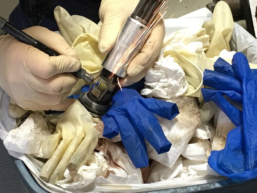
Was this done as an upgrade on a new pump prior to installation or on a pump that had been removed. I'm not sure I'd be willing to take a dremel tool and the associated sparks to a pump that had been submerged in fuel previously - that sounds like a recipe for disaster.
Thanks for the replies, but my original questions remain:
1 - Is it proper for fuel to be pumped out of the two small holes in the body of the pump at the intake/strainer end?
2 - Is there a fuel proof shrink tubing that can be used on the wires?
BTW, I had reported that a wire had broken in the original post. It was not broken: the wire had been poorly soldered and had simply pulled out of the cup of the connector, and another wire was only a slip fit and easily pulled out too. This was not corrosion as the wire ends were shiny and nicely tinned as were the terminal cups. There was not enough solder to properly bond those two connections, so I was suspicious of the rest and trimmed away the shrink tubing. Only one of the remaining connections was properly soldered, the other was barely adequate.
Was this done as an upgrade on a new pump prior to installation or on a pump that had been removed. I'm not sure I'd be willing to take a dremel tool and the associated sparks to a pump that had been submerged in fuel previously - that sounds like a recipe for disaster.
The in tank pump had been pulled from my tank after draining the tank. The original hose was cracked. After the pump had been out and dry, it was repaired and replaced. No problem with fumes or sparks.
To answer how to go drain the tank, this is how we did it, one of many ways, but this was the quickest.
The tank was drained from the passenger side fuel rail with a fitting/hose attached on the end of the rail. Using a long jumper wire and switch to the fuel pump relay socket in the CE to operate the external fuel pump. The tank was about quarter fuel and this was much quicker than draining from under the car at the tank.
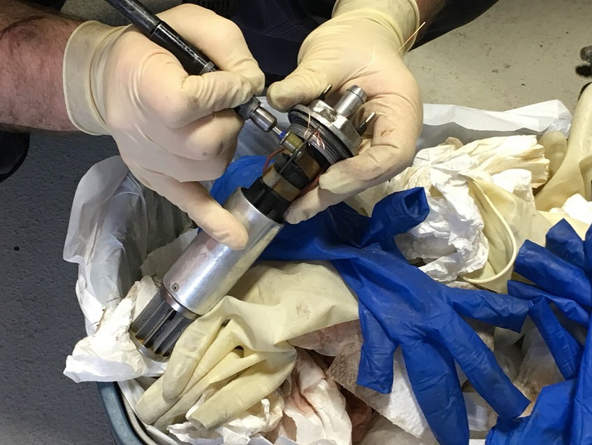
Pump as it came out of the car Pumps after rebuild Exploded view of the pump internals
Happy to share my experience with you but kindly note I was not entirely happy with what I did- more a question of the only way I could make it work in the end.
About 4 years ago I sensed a problem with the in tank pump that I had not previously excised on this particular 928 that I have owned since acquisition in about 2006. Sure enough when I pulled the pump the hose had gone . To my astonishment I found that the hose installed had been fastened by cable ties. I looked at the service history file and noted there had been an intervention around 2002 wherein a problem with the in tank pump was reported/diagnosed. Thus my assumption that a second hose had been in the car for about 12 years by the time this event I refer happened in 2014/5. This also happened on my late 1990 S4 about 2001 when the car was 11 years old [I lost the car in 2005] so I concluded that the hose is good for 10 years.
As it happens I also had the in tank pump from my late S4 in my parts bin but the internal wires had gone. These wire are very slender and fracture from the posts they are soldered to very easily.
Initially I figured I would purchase a new in tank expecting $120 plus 10 years of inflation but when Roger advised me how much they had shot up to I thought the hell with that. I got one of Greg's little hose kits from Roger as a cure for the hose issue and got to work on my spare pump initially. The motor and pump assembly is encased in an aluminium tube that is peened over at the end - nothing more than that holds it all together. I wanted to see what was inside the pump so carefully pulled it apart and was somewhat surprised when I found it was in fact a two stage pump with a tiny little impeller that looked more like a baby starfish.
I then had to figure out what to do about the cables. Earlier research suggested that the best insulation for auto cables in PVC because of its resistance to petrol. Whether or not there is insulation on these cables is not an issue immersion wise because petrol is not ionic, i.e. it does not conduct electricity, however we do need to avoid a short so integrity of the insulation is important in that regard. I have small bobbins of cable specifically for automotive use that is size 1mm2. I also have some small diameter heat shrink sleeves with integral glue. Initially I soldered new leads to the motor terminals and slipped a short length of the heat shrink sleeve over the terminal and shrank it into place- no problem. So did the same with the other pump. This was a small mistake in that as I duly found out, soldering the cables to the terminals in the cover was much harder as they are recessed. So, I then had to figure out what to do with the other end. By trial fit it seemed that there was not enough room for the construction I used at the other end so had to compromise by omitting the heat shrink at this end. I installed the cables a bit longer than the stock items to leave a bit more room to work with when installing the hose and thus put a neat fold in the cables after the hose was fitted.
Now I had to fit the hose. Leaving the cables a bit longer was a smart move but crimping the hose proved difficult and when trying to fit Oerliker clamp supplied with Greg's kit the first pinch failed for some reason seemingly pulling the clamp apart- I presume I was a bit ham handed with the pincer tool I used but..? Now I had to figure out what to do as I had no spare clamps of this type. It seemed as though there was no room for a jubilee clip and scratched my head. Greg's hose and the petrol hose I planned on using for the spare pump both pushed on quite tightly so I wondered if I could get away with no clamp at all. In the end I figured that if the zip ties previously installed had lasted 12 years then figured there was nothing to lose- if the tie failed the hose might hold and if it did not the worst that could happen would be the hose coming adrift- hardly a disaster so I used a zip tie to put a little pressure over the barbs.
Is it perfect probably not - but it has worked for OK the last 4 years and on the plus side I have a spare pump standing by [somewhere].
Thanks for the replies, but my original questions remain:
1 - Is it proper for fuel to be pumped out of the two small holes in the body of the pump at the intake/strainer end?
2 - Is there a fuel proof shrink tubing that can be used on the wires?
.
If fuel is coming out of the casing I would think it might be because the pump assembly may be a bit slack inside the outer casing- if so support the discharge end of the casing best you can and gently tap the other end with a small hammer to put some closing pressure on the casing where it folds over to encapsulate the innerds. I cannot visualise that fuel should come out of the casing on a pump that is working correctly.
I have shown what I did heat shrink wise in my earlier post- whether it will hold up remains to be seen - I rather feel the heat shrink is not that critical but would have preferred to see such both ends had I been able to fit it.
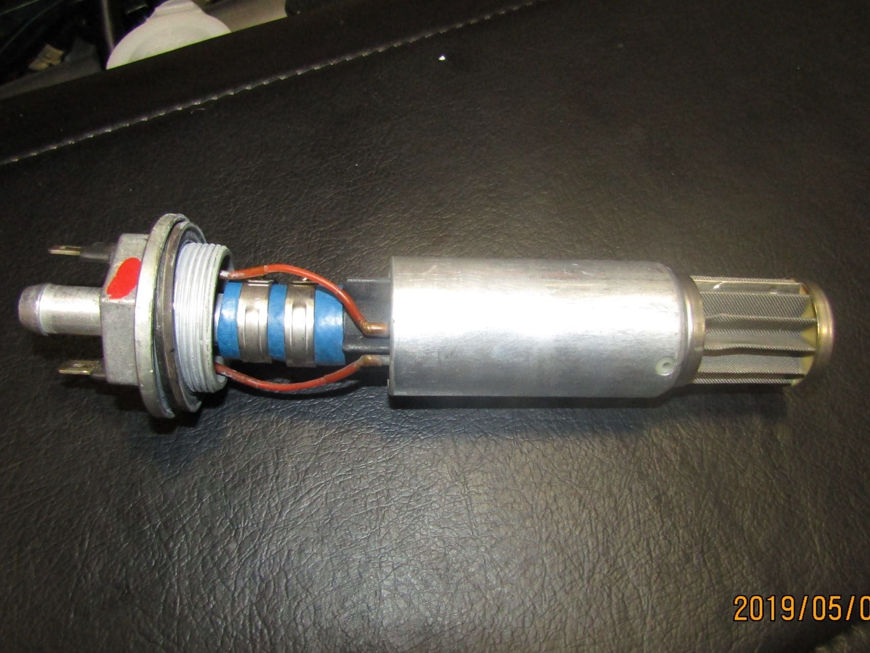
Regarding the holes in the pump housing and discharge from them: the first photo in your post above shows the hole at the screen end of the pump body, The hole in the aluminum casing is lined up with the hole in the plastic of the pump body, but in the second-to-last photo the holes are not aligned. The outer casing is not keyed to the internals and can rotate to cover the holes.
These are the holes (two of them, on opposite sides of the casing and pump body) that fuel is happily pumped out of as well as the actual outlet port.
Aligned or not aligned? Which is correct (and of course, is fuel supposed to exit them....)?
Your observation is interesting and quite frankly I do not have a definitive answer. The pump with the blue hose is sat in my spare parts bin and just took a look at it. The photo of the pump with the black hose is currently in service and that photo is less determinate in the as built condition because of the angle but the point is I did not take that one apart. Basically I practised what I intended to do on the blue pump before applying it to the black pump.
I am tempted to pull the blue one apart to take another look in case I missed something but the trouble is the casing was showing signs of fatigue after being opened and then closed again so I am a bit reticent to risk the utility of the spare.
Now for purposes of discussion, the in tank pump fascinated me. The last pumps I worked with were each rated at 5MW, had double suctions, double seals and had self balancing impellers flowing 22,500 m3/day and developing something in the region of 1300m head. Those pumps I understood inside out and back to front. These tiddlers puzzled me! The strainer element just clips under the rolled out collar so the plastic you see through the hole is the casing element which has two parts- the suction element and the discharge element. The suction element has a hole in the centre- no mystery there but the discharge element is what really puzzled me in that I could not figure out the flow path which should be tangentially out of the pumping volute and the discharge then has to get into the suction of the second stage and this I just could not fathom out as I could not spot any internal passage ways in those plastic components. However I know it seems to work so gave up at that point.
Perhaps at this stage may I ask you to get a paper clip or something similar and measure how deep that hole in the casing goes. If it is completely open it will penetrate close to the pump centre line. If it is in the outer casing then it will only be about 3mm deep, if that.
At the moment I cannot think of any sensible technical reason why there should be a hole there - obviously it is not for weight saving! There is no indexing features on the cartridge and no reason for there to be. There is no need for venting the casing and in any event if there was then the pump orientation would be critical and that is just not the case. The only thing I can think of is whether it might be a "design feature" to help bleed off a little pressure in a controlled manner. to help prevent the cartridge from blowing out of the casing but that to me just sounds so ridiculous.
I will do a bit more thinking on this one while you measure the hole depth. The other thing you can try if you are so motivated and have a setup to test pumping, is to run the pump for 30 seconds and just see how much it pumps in that [or any other time]. I have searched high and low for data on these pumps over the years and found absolutely squat.
The pump mystery continues. Both holes enter a cavity, and a fine wire inserted straight in will reach about one half inch before it stops. Also, something - likely the top impeller - can be seen to spin when power is applied. Assuming that ejecting fuel from these ports is intended and not a malfunction of my pump, maybe this is some kind of centrifugal process intended to sling small particles that got through the screen out the holes? Maybe I am thinking about this too much.........
Anyway, this is the only pump I have seen and it functions as described, and if anyone has immersed one of these pumps to test under power, please let me know whether or not liquid is expelled from these holes.
FWIW, other photos on the board show that the aluminum casing is aligned so as to expose the holes in the underlying plastic.
I will try to find some method of testing the throughput. A little tricky as this pump offers little restriction even when not powered, so liquid will flow through without the pump to help, and anything that would pressurize the output would skew the result. Needless to say, it could be a messy, if interesting, experiment. Come to think of it, I might still have an old aviation fuel flow gauge and sender... if I can find it, and if it works...
Hi,
The fact that the hole goes through like that suggests it is no accident and thinking aloud the only credible thing I can think of is whether it is a safety feature of some kind. The motor is not sealed and as far as I could tell fuel flows across the motor to cool it before it actually leaves the pump through the outlet nozzle etc. The bit that has troubled me about this setup is what would happen in the event of a really low level as in when the car stops because fuel is not coming through. At such point there would likely be fumes and air and a DC motor spinning. My expectation is that the motor should be non sparking for obvious reasons. If the pump is not flooded it will immediately cease to develop any head, flow will stop and the motor will die- been there, done that and no "kaboom". As to what the safety feature would do is the bit that baffles me. If there was any danger of a spark and conflagration the system would just not fly- that or there would have to be a trip function to cut off the pump at a specific low level of fuel in the tank.
If you do manage to jury rig a flow test the easiest/safest way to do such would with the pump mounted in the tank and a separate pipe on the outlet connected to a bucket. I could never find the rated conditions for the pump but the flow should exceed that of the main pump which is specified in the WSM's. That the fuel will flow out under its own head from the fuel level is true so the logic would be to measure the flow rate without the pump running and then with the pump running and the difference logically should be what the pump is adding, not entirely but near enough or so I would think.
Need to do a bit more thinking on the holes though!

 05-16-2019, 07:21 PM