When you click on links to various merchants on this site and make a purchase, this can result in this site earning a commission. Affiliate programs and affiliations include, but are not limited to, the eBay Partner Network.
Can't get clutch pressure plate and release arm apart
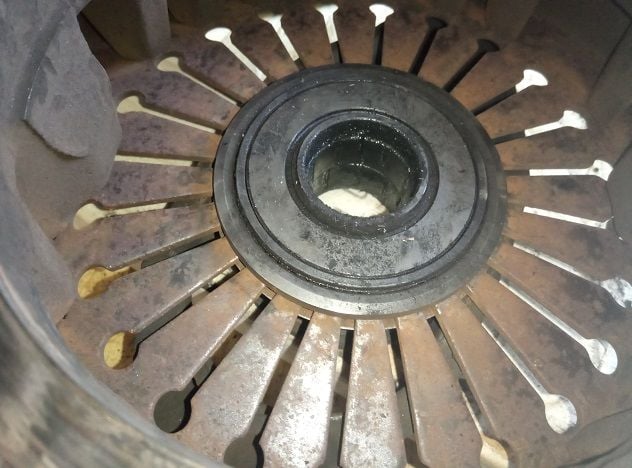
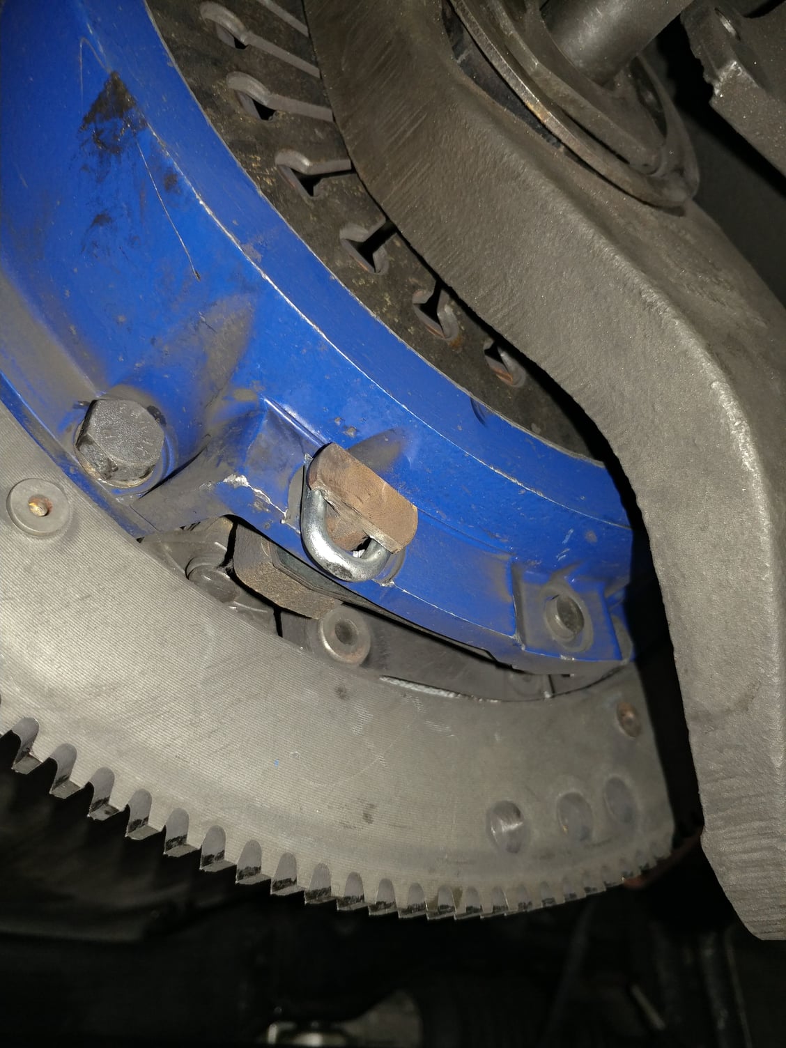
I've got the clutch out of my 1987 S4 but I can't get the old bearing and release arm off of the pressure plate. My understanding is that with shims installed, the release arm on a board, and moderate pressure downward the fingers will flex enough to expose the lock ring. I've tried various sized shims from 1/16 up to 1/4, applied north of 200 lbs, and no movement at all. The lock ring is never exposed at all.
What am I doing wrong? Would it be best to just cut the nubs off of the old bearing so that the release arm can be removed and then just abandon the assembly? I have a new pressure plate, bearing, and associated rings. So, all I really need is the release arm.
I got it apart by removing the smaller lock ring that holds the bearing assembly together. I then drove the inner sleeve out of the bearing and outer ring, freeing it and the release arm from the pressure plate. I don't know if that's the right way to do it, or if there is a better way. But, it worked and it's reversible without destroying anything.
I took some measurements and got the release lever part number. This is what I found:
Old and new release bearings are both 34mm ID
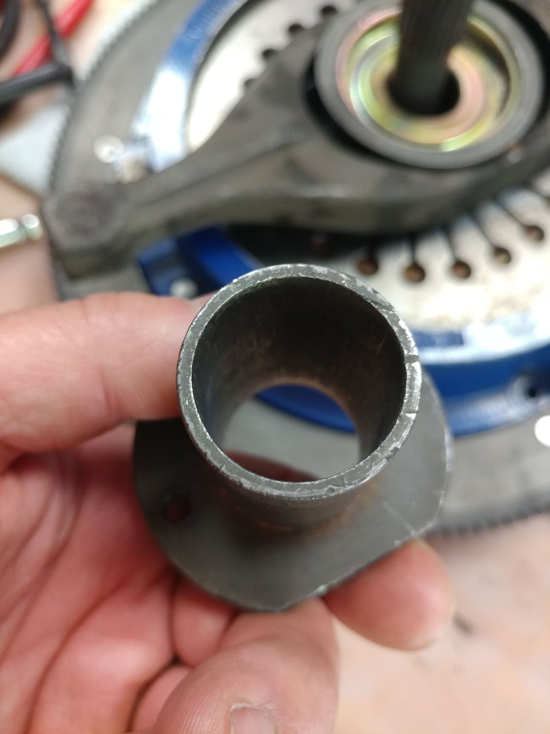
Guide sleeve is 31.8mm OD
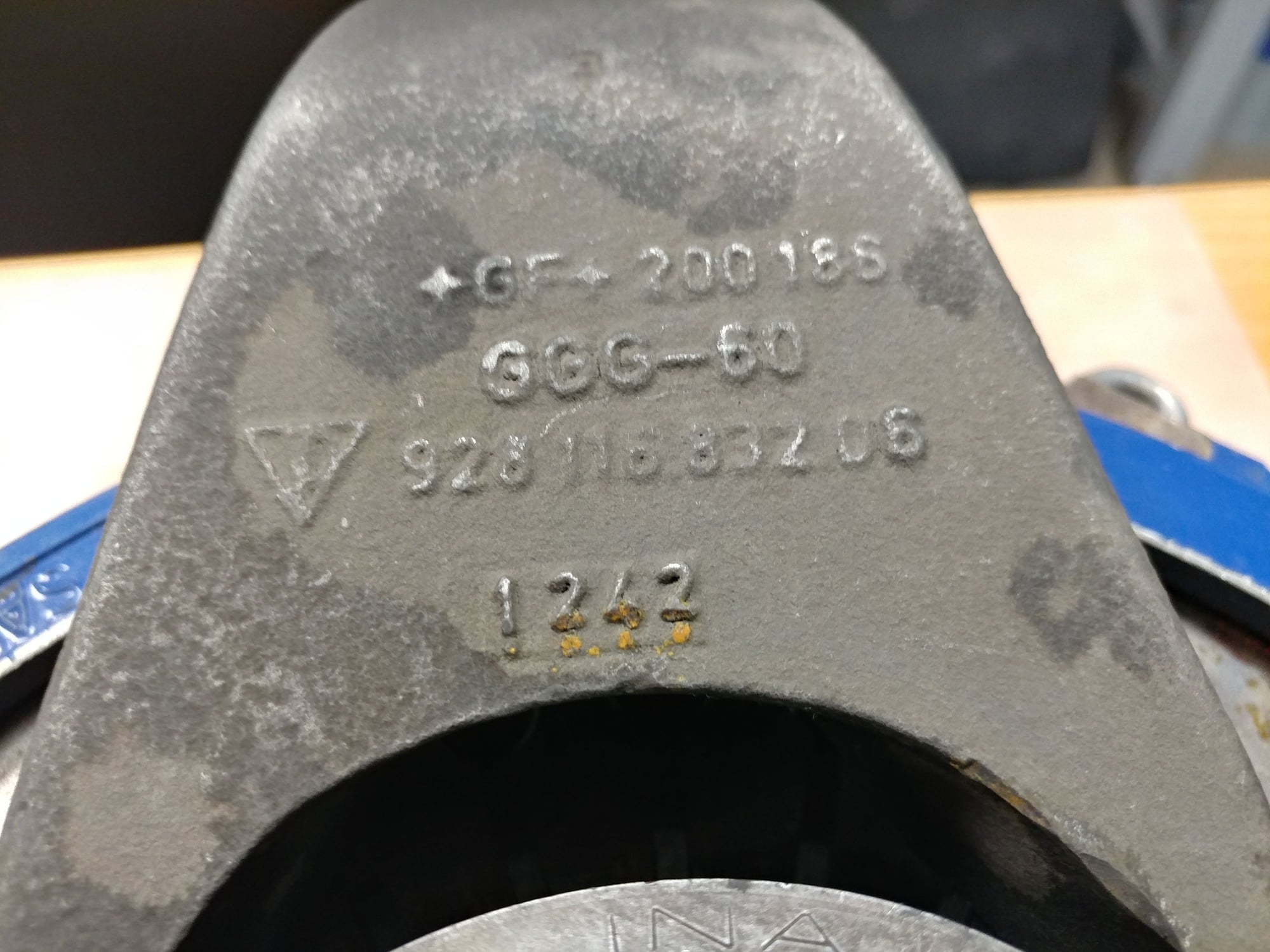
Release lever is part # 928.116.832.07
If I'm interpreting the WSM correctly, that means that the release lever and release bearing fit each other properly (old style). But, the guide sleeve is wrong (new style).
Do I have that correct? Is it appropriate to just get the correct guide sleeve (33.8mm ID) and run with that, if it's even available?
Or, is there good reason to buy a new release arm and new release bearing and use my existing guide sleeve?
Here is another thing that may or may not be related. The old clutch disc is almost exactly the same thickness as the new clutch disc, it doesn't appear to be worn much. But, the clutch slipped under WOT in 4th and 5th gear. The flywheel looks fine, no grooves, no significant hot spots. So, I'm not sure if the difficulty in disassembly indicates a pressure plate problem, which caused the slipping, or if the mismatch between the guide tube and bearing/arm was the culprit, or what.
well as Greg has suggested your difficulties indicate your parts are not all for the same assembly
different release arms will work properly with the correct for that assembly TOB and guide tube
what usually happens is that the release arm the TOB and guide tube all get superseded to the GTS version.
So....since this work was all done back in Salt Lake City, can I somehow give you credit for it?
It sounds like the best move is to order a new release arm and bearing to match the newer style guide tube. Obviously, the guide tube played no role in getting the pressure plate assembly apart, but maybe it affected how much pressure could be applied to the clutch.
The new pressure plate assembly is from Spec, made for the 1987. Any concern with it fitting properly, or did those dimensions not change with the newer release arm and bearing?
The original style T/O bearing hasn't been available for many years....chances are, you have a late style bearing with an early arm.
The original arm had a curved surface where it contacted the flat surface of the original T/O bearing.
Porsche found that clutch operation was smoother with a flat surface on the T/O arm and the curved surface on the T/O bearing....both parts were superceeded.
Note that a flat surface goes with a curved surface, regardless of early or late. It is extremely important this occurs.
Chances are, you have a curved T/O fork with a curved T/O bearing (common mistake.)This results in a very unstable condition, which means the T/O bearing usually pulls up the clutch crooked. It is also really difficult to remove the T/O bearing retaining clip, because of the extra dimension from the two curved surfaces touching each other.
You need an "09" arm.
I"ve got 6 brand new ones,, in inventory, ready to ship.
Thank you. That helps. You're right, both of the bearings in my possession have curved mating surfaces. The release arm has flat mating surfaces, but they look like they may have been ground down. Either way, it's a 07 part, and the combination didn't fit together well.
I will call you this morning to order a new release arm.
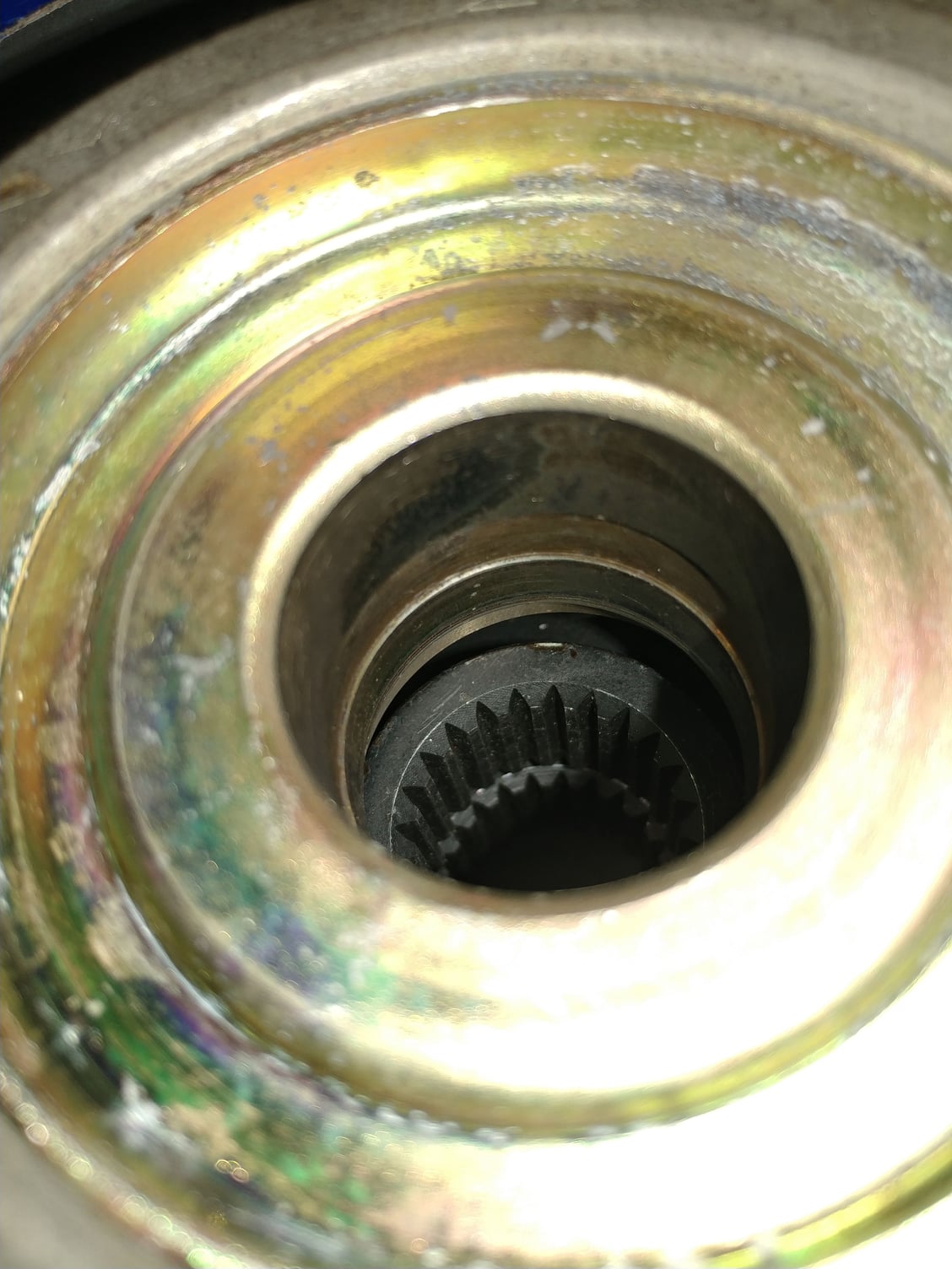
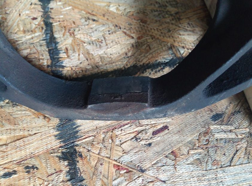
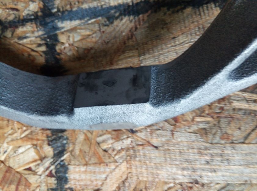
Put a straight edge across that part in pics 2 and 3. My bearing was dragging/catching on it
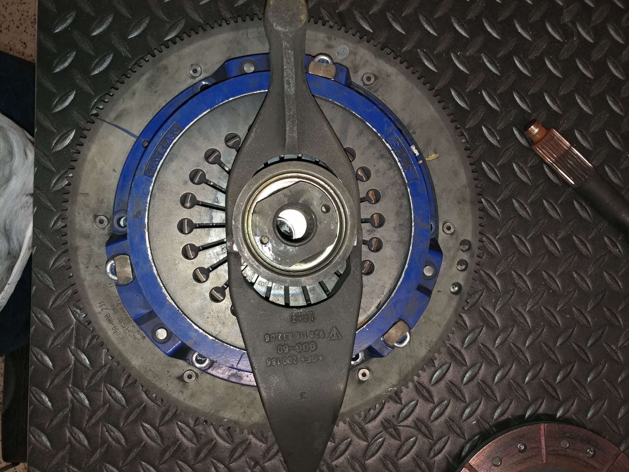
I was more worried about the groove inside the throwout bearing and also how the thrust arm is curved and the throwout bearing flange is straight, or is that part ok (picture 5).
Hope these help, mine is still on my bench. I have the groove in the inner part of the bearing carrier.
I've just read Greg's post in detail and need to have a closer look at my parts too. I had unstable clutch engagement which is why mine is out.
86.5 car. Shouldn't have commented on '87+ car. The sleeve wear is worth a look tho. Good luck
It was a long time ago I took these tbings apart but I remember that the procedure (not by WSM though) was to stand on it while bending over to release the lock ring. But first try touching your toes while bending over to train for this particular job.
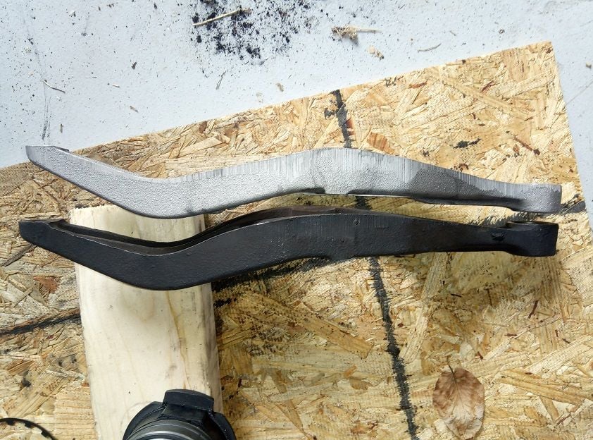
The new clutch release arm arrived today. I took a few photos to show the differences, but in summary:
The new release arm is 0.5mm thinner than the old one
The old one had a recessed curve on the inner surface (I don't know if that's normal or mine was modified/worn)
There does seem to be a subtle side profile difference between the two arms
Assembly was pretty straight forward. Another poster installed the lock ring by kneeling on the pressure plate and working the lock ring in by hand. That didn't work for me. Instead, I did not kneel on the pressure plate, I just rested the entire assembly on a 2x4 so that the ends of the release arm were suspended. I then started one end of the lock ring into the groove. The concave washer that you compress in order to expose the groove is very light. Even just rocking the pressure plate to one side is enough to expose the groove on that side. Once the lock ring was started, I walked around its circumference with a small flat head screw driver, carefully placing its tip only on the lock ring, and then gently tapping the end of the screwdriver with a medium weight dead blow hammer. It very easily popped into the groove with one hit at each point. About 2/3 of the way around it pulled itself into the groove the rest of the way with no help. That technique was very easy, required no special balancing skills, and provided a lot of control.
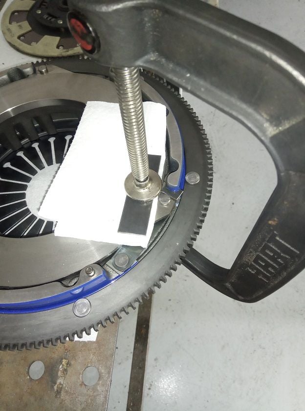
I've also included a photo of the shim installation method that I used. The WSM calls for 2mm thick shims. I used 3/32 bar steel cut into small tabs. 3/32 is 2.38mm. Rather than attempting to press down on the spring pin as shown in other posts, I used a folded up paper towel under a piece of 1/8" thick bar steel on the main friction surface. The C clamp is a large 8" clamp. This method gave me a more stable surface on top and bottom, and plenty of room to insert the shims.
Thanks for the help on identifying the problem with the mismatched parts. That was probably the root cause of all of my clutch problems. As soon as the pilot bearing removal tool arrives, I'll replace the pilot bearing and put everything back together.
Shim installation method with shim in place:
Side profile of the old (bottom) and new (top) clutch release arms:
Inner bearing mating surface of old clutch release arm:
Inner bearing mating surface of new clutch release arm:

 04-16-2019, 07:45 PM