When you click on links to various merchants on this site and make a purchase, this can result in this site earning a commission. Affiliate programs and affiliations include, but are not limited to, the eBay Partner Network.
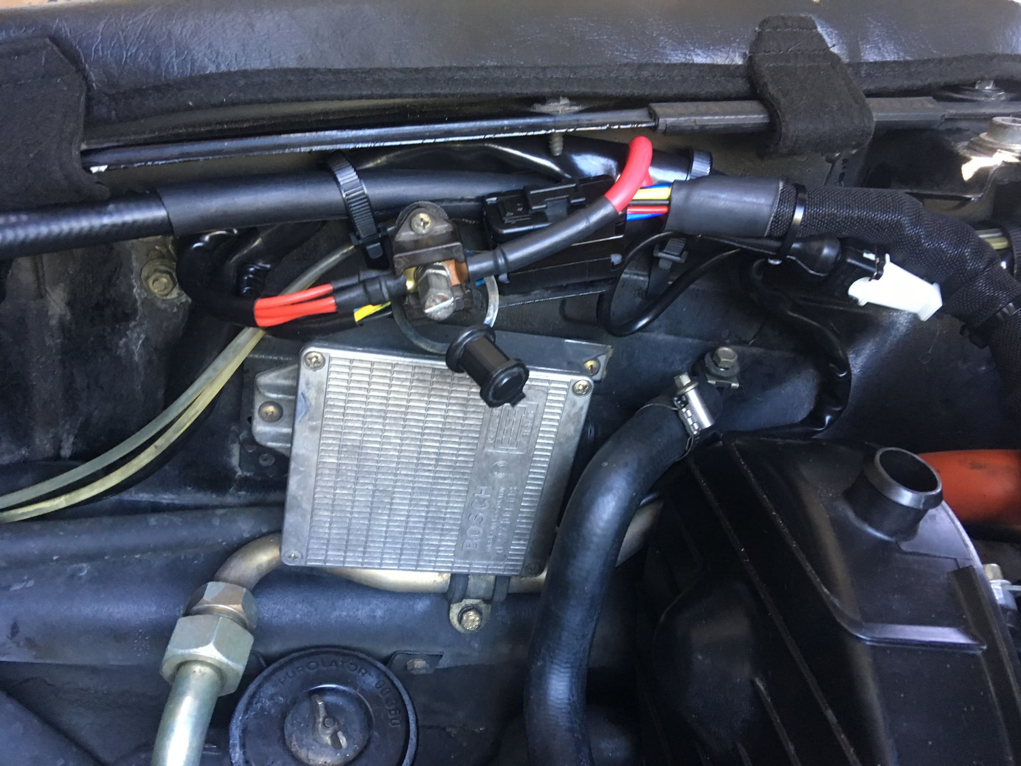
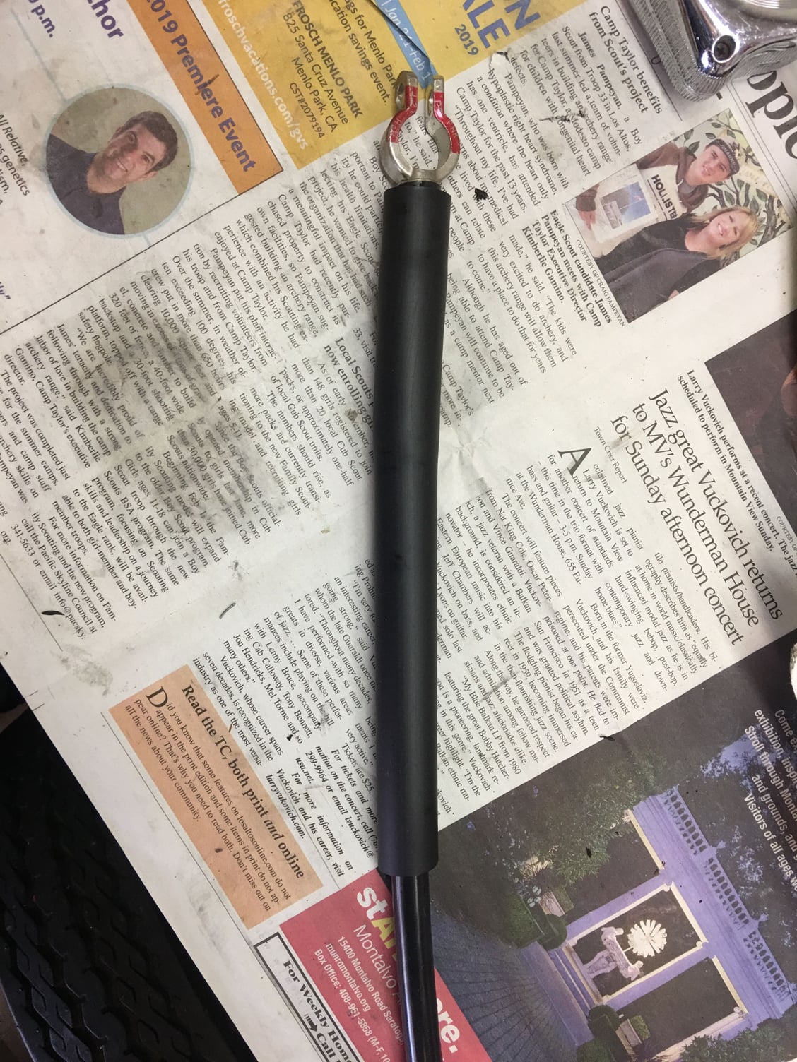
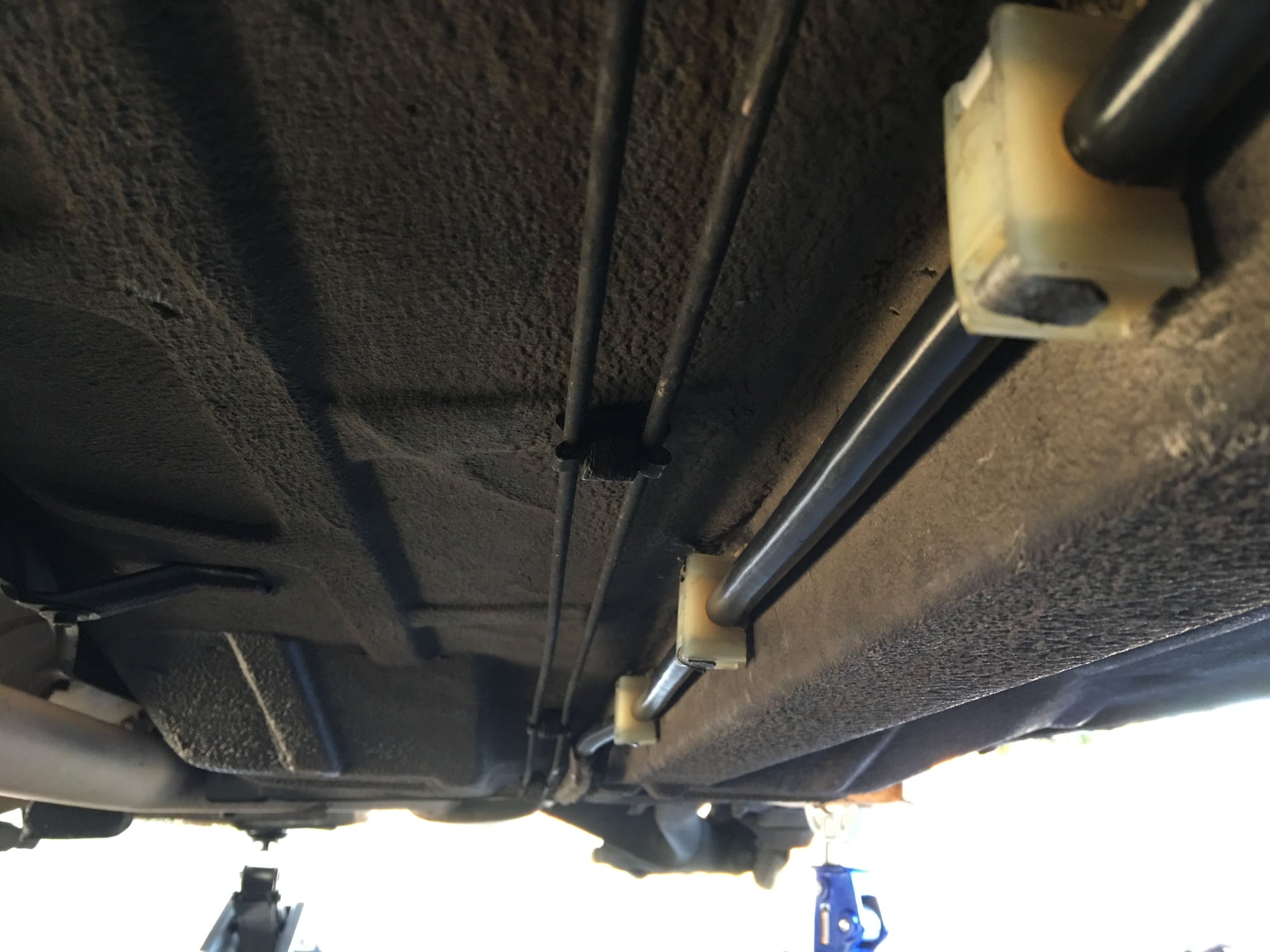
Josh, you're asking about the little cover for the actual jump post? Mine's original, so haven't had to look into that. I DID purchase a new (big) jump post cover visible in the first photo, though, as my original had an unfortunate accident some time ago that involved a fall to the undertray followed by almost getting sawed in half by a moving belt... I shudder to think of it all lol!
And that beautiful harness is from Sean. Yes, it's covered in a very nice fiberglass type fire sleeve, and the sections around the lower part of the engine have a different sleeve that is oil impenetrable (not sure but think it's silicone based).
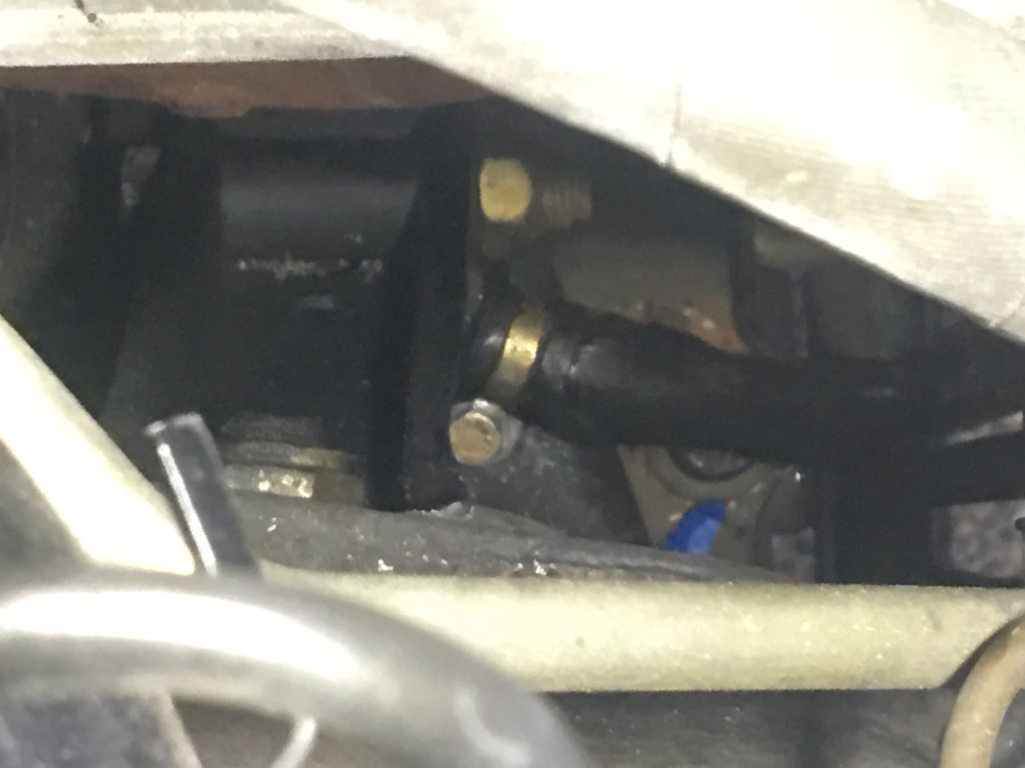
Fun fact (that I remembered while looking at the jump post pic): Porsche really, REALLY seems to have thought out even the smallest details on the new engine compartment harness I just installed. In the picture of the jump post area, above, you can see that there are three smaller red wires at the jump post (in addition to the big fat one that runs to the alternator and thence to the starter). The three wires attach to the post via two lugs. Those two lugs are ever so slightly different. One lug has a greater distance between the center of "O" in the lug, and the wire crimp area. You can see it if you look closely.
The two lugs are back-to-back, flat backs together and wire crimp sides facing away from each other. Well, it turns out that the longer lug goes down first, then the shorter lug. The longer lug is JUST long enough to clear the outside of the plastic connector, and the shorter one is not. I tried placing the shorter one in first, in my first attempt at a trial placement, and saw that the protruding crimp area hit the outside edge of the plastic connector. The lug wouldn't go in flat. That's when I noticed that the second one was slightly longer -- just enough to clear the plastic connector and allow a clean install. Of course, one may ask WHY they didn't just use two long lugs as there is no real reason to not allow interchangeability. But as with so many things German, perhaps it's best not to ask why :-)
Gotta love the engineering in these cars, down to that level of detail.
Made some more progress installing Sean�s harness tonight. I had left the starter end uninstalled until I was ready to install a new battery positive cable (I may as well do them both at the same time).
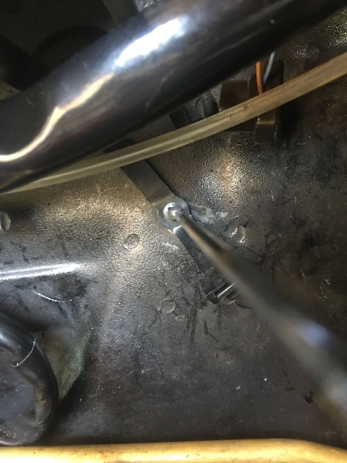
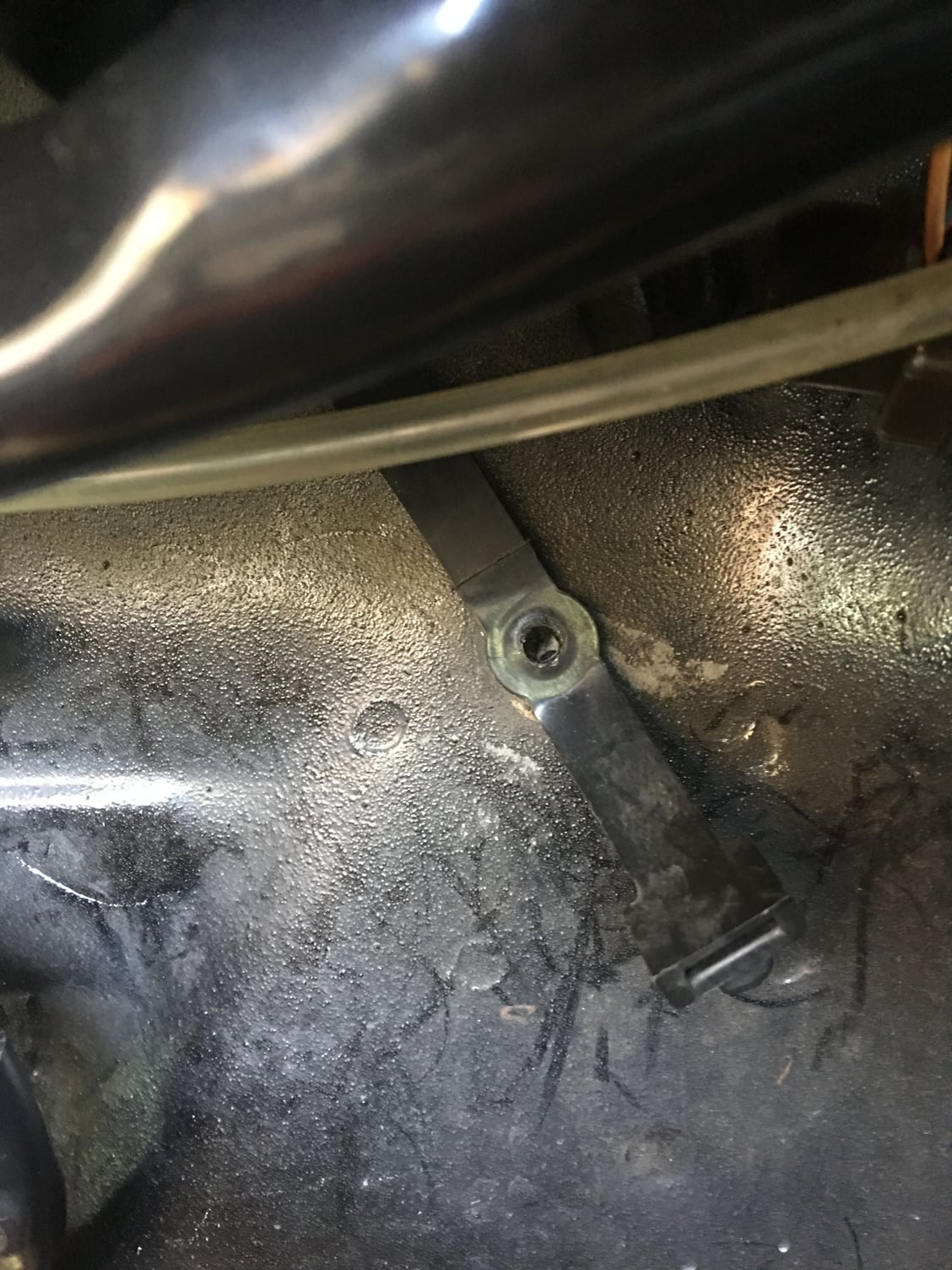
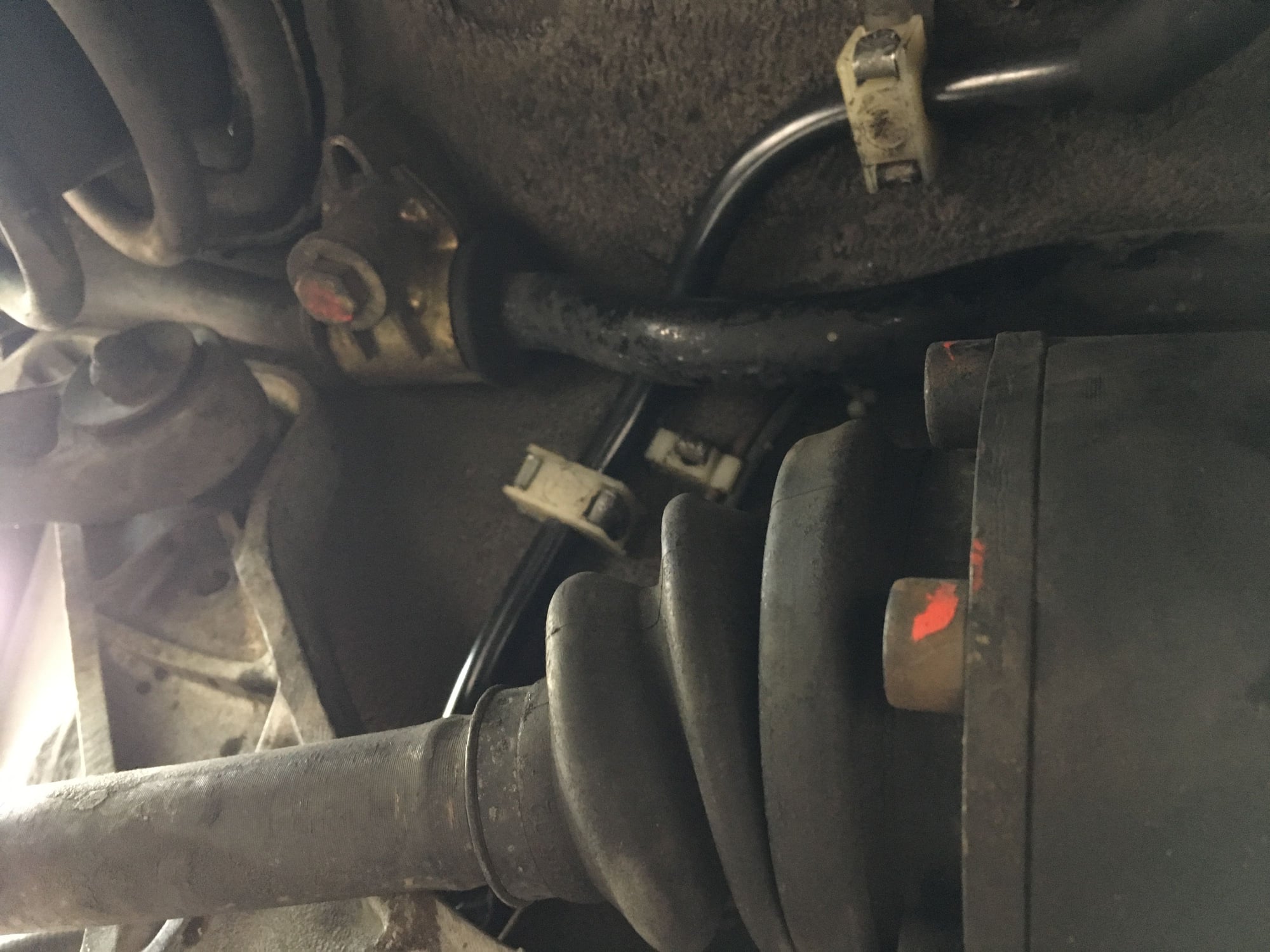
I�ll document the battery cable separately but I came across the single hardest part of installing Sean�s harness: replacing the P-clamp hold down near the engine mount!!! It�s held in place by a single 6mm bolt. But there�s really only access to the bolt head from above (using a huge socket extension) and the nut only from below, and even then it�s above the steering rack bellows. I had a helper and it still wasn�t easy. I first cleaned the P-clamp, removed the rubber and coated it with Molykote, reinstalled the rubber and placed it on the harness as I fed it through the mount area (�before� pictures very helpful here, especially as the cable threads theough the power steering hard lines). After trying and failing to even get the bolt into the hole, I removed the oil filter and could just barely reach up to get the bolt in. I then used some Molykote to keep the washer in place, then placed the nut in place with hemostats and my helper tightened the bolt from above. Phew!!
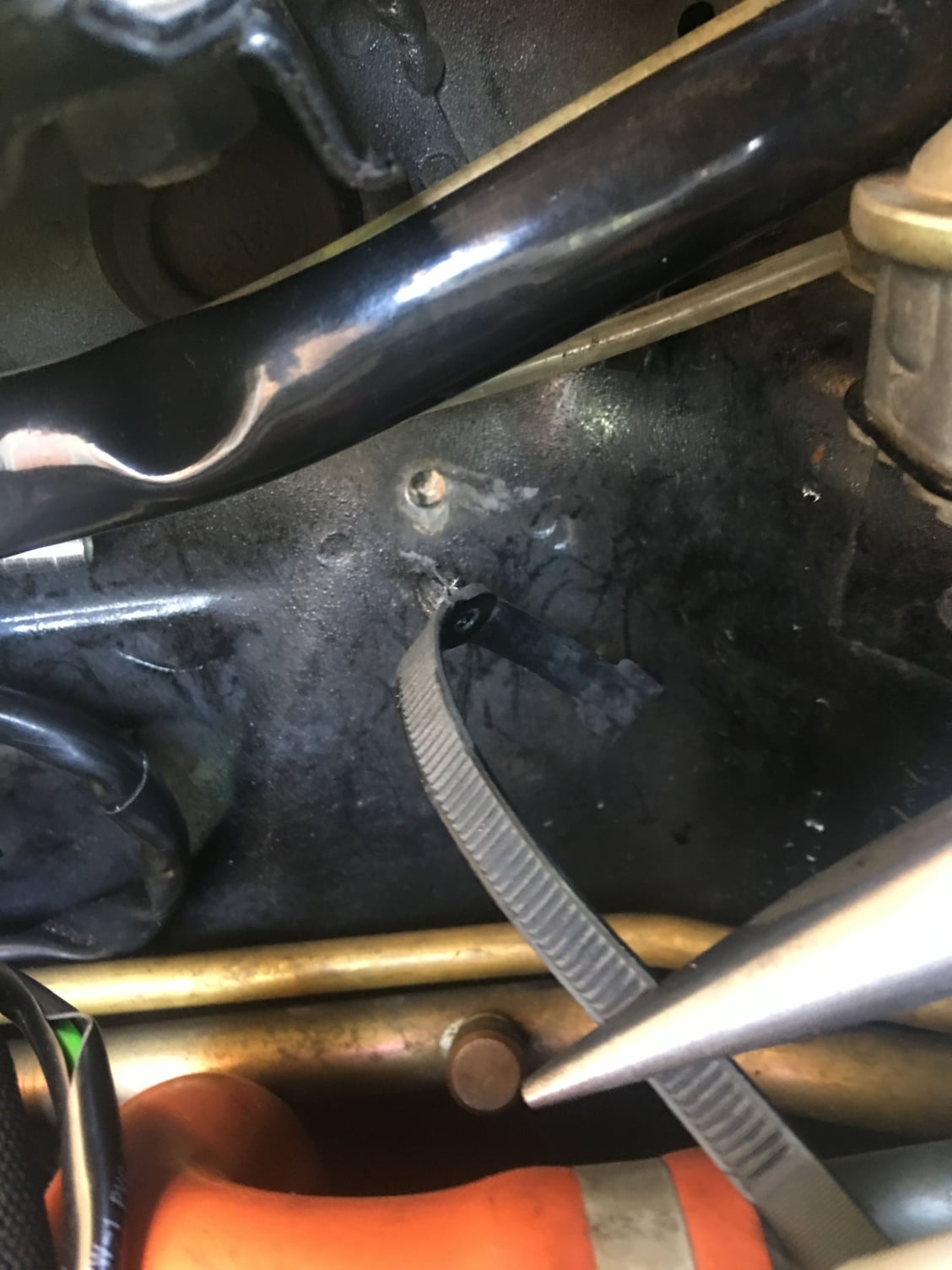
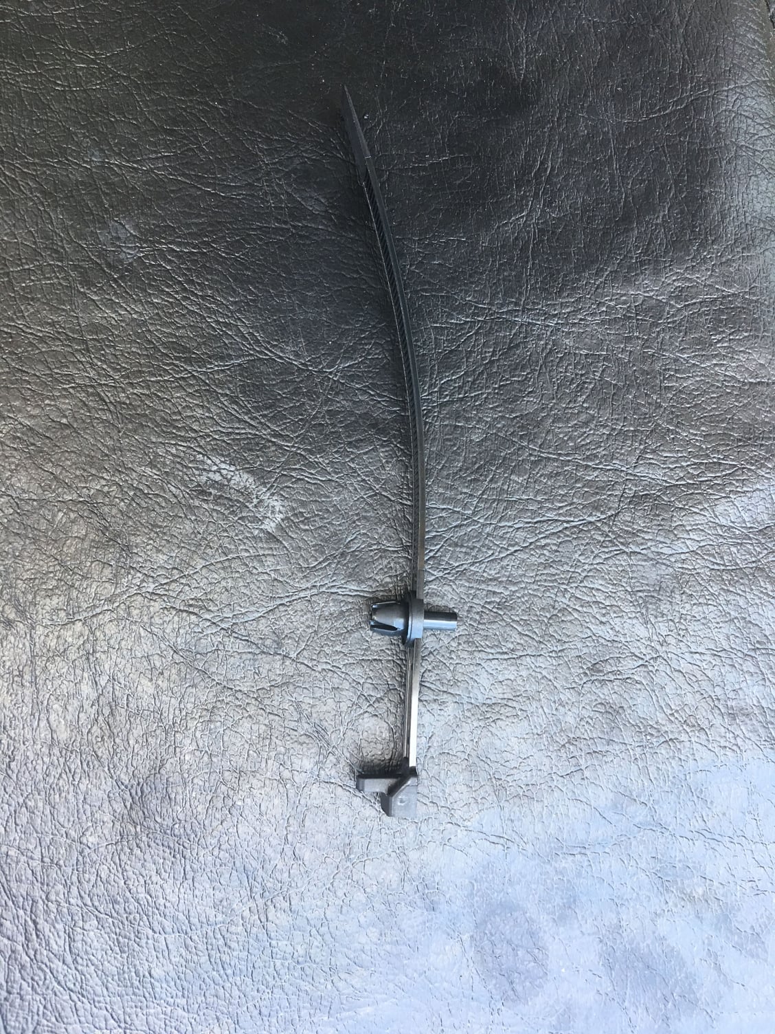
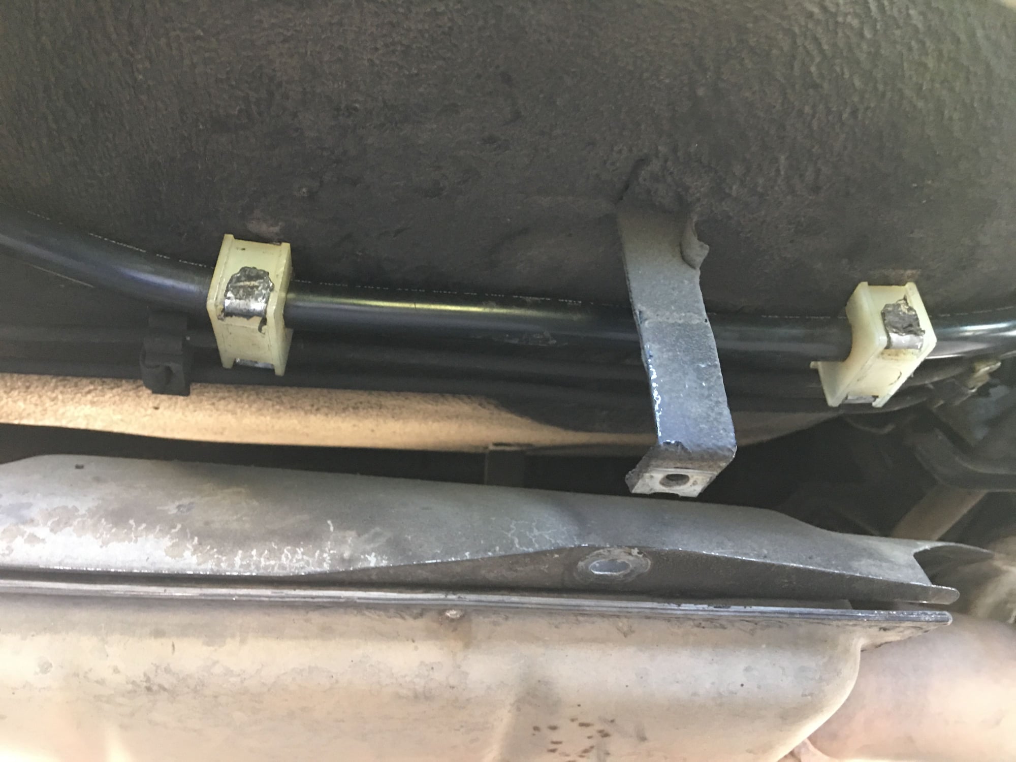
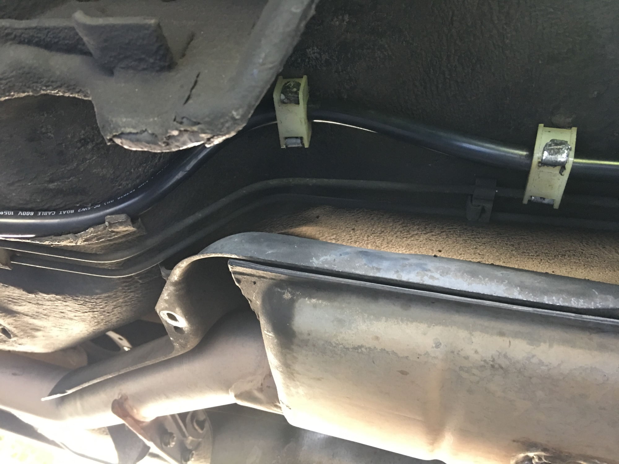
I just received another care package from Roger, including the Porsche zip-tie hold downs for the engine compartment harness. The ones in the car were showing their age but otherwise in reasonable shape, except for the one directly under the passenger crossbar mount (actually a critical location) which wouldn�t stay zipped. From the passenger firewall to the driver�s headlight there are twelve of them! I replaced them all, and discovered along the way that one had broken off in the distant past leaving its base behind, just behind the intensive washer reservoir, and one either broke off leaving no trace or was never installed, between the crossbar and the P-clamp immediately behind it.
With the new zip ties in place, the harness correctly routes well below the crossbar now. Before, it touched up
against the crossbar mounting plate which has some sharp edges.
While I was at it, I decided to wrap the radiator-to-expansion tank return line with 1/2� PVC thin flexible sprinkler pipe I picked up at Home Depot. I plan to use this as Dr Bob suggested on the new battery positive cable, but I bought a roll of it and it turns out to be a great fit for this coolant return line too. The idea is to help shield the engine compartment harness which is otherwise in direct contact with the hose along the passenger fender. I cut it to length, then cut a split line with a razor blade. With a spray of silicone lubricant the hose pops right in and can be pulled either way for adjustment.
Original zip tie To remove, press out the plastic center piece which acts as a lock Center piece removed The zip tie can now be removed from its mounting hole New zip tie waiting Some of the many installed ties, and here you can see the PVC pipe over the return hose
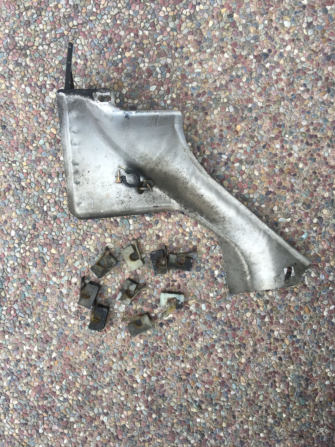
I managed to get the battery cable out. There was one hold-down which was more difficult than the rest to remove, trapped by the brake hardline in the rear wheelwell, but by loosening the brake hardline hold-down I was able to nurse out the cable hold-down from its long metal fingers.
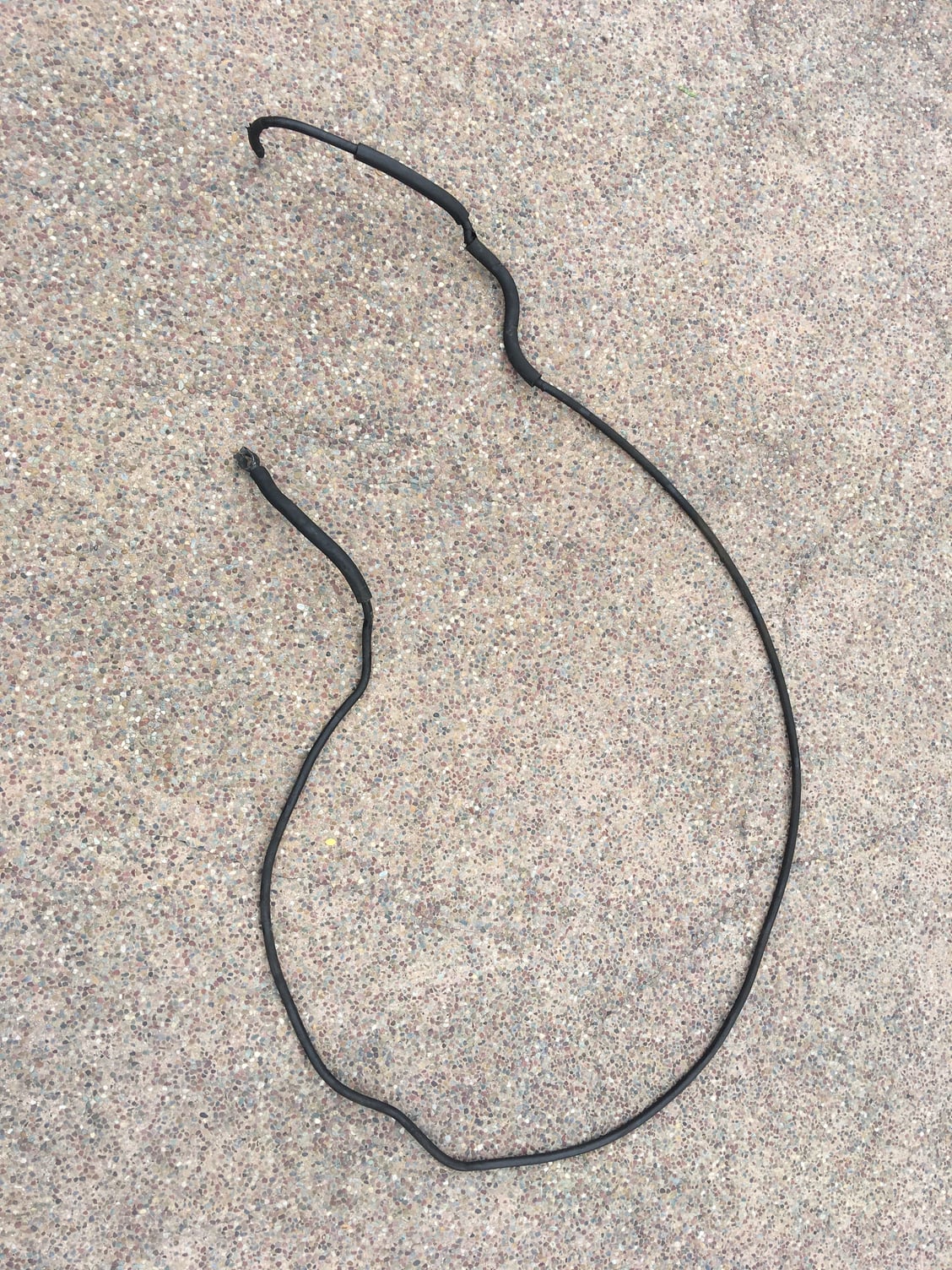
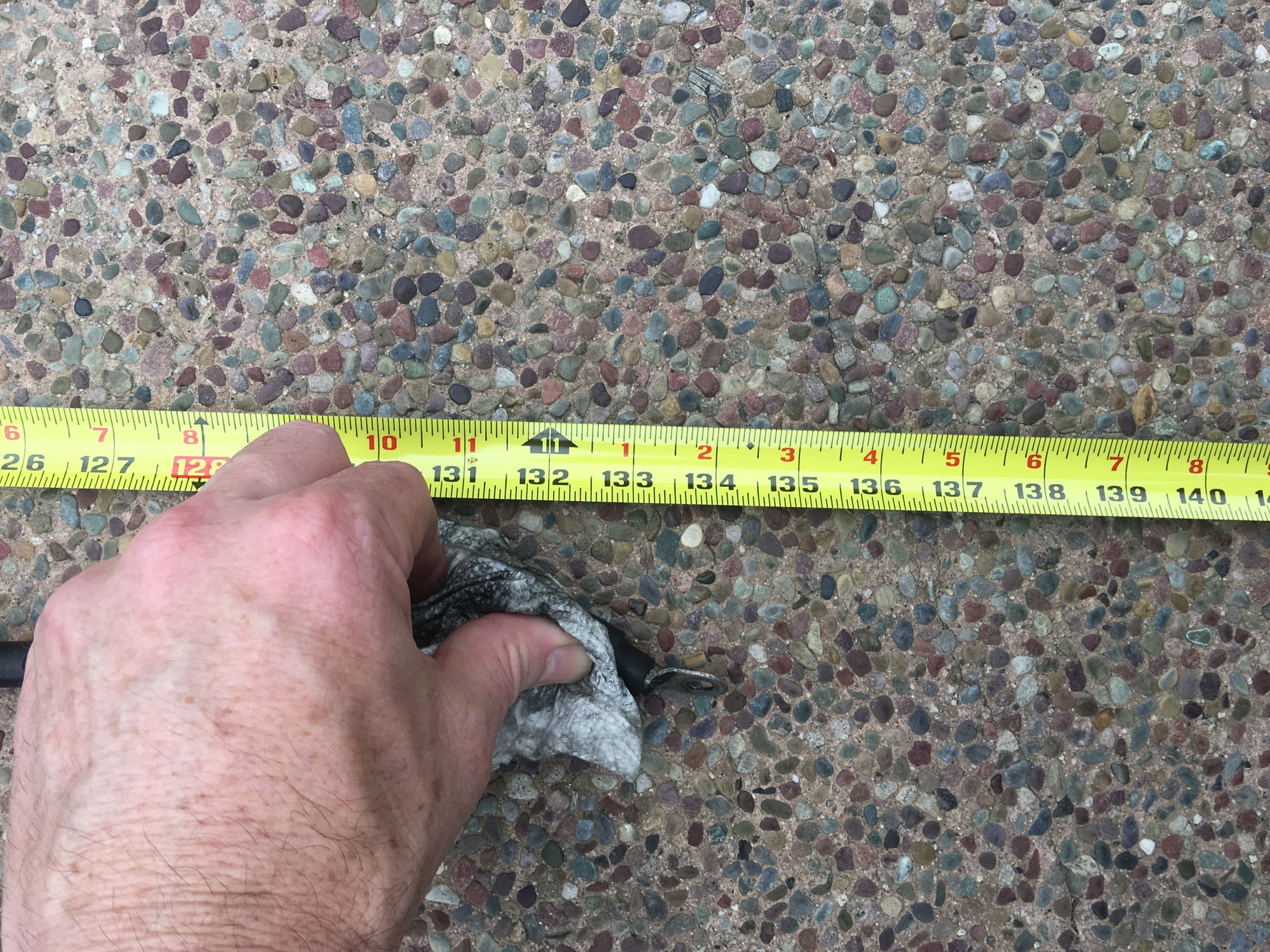
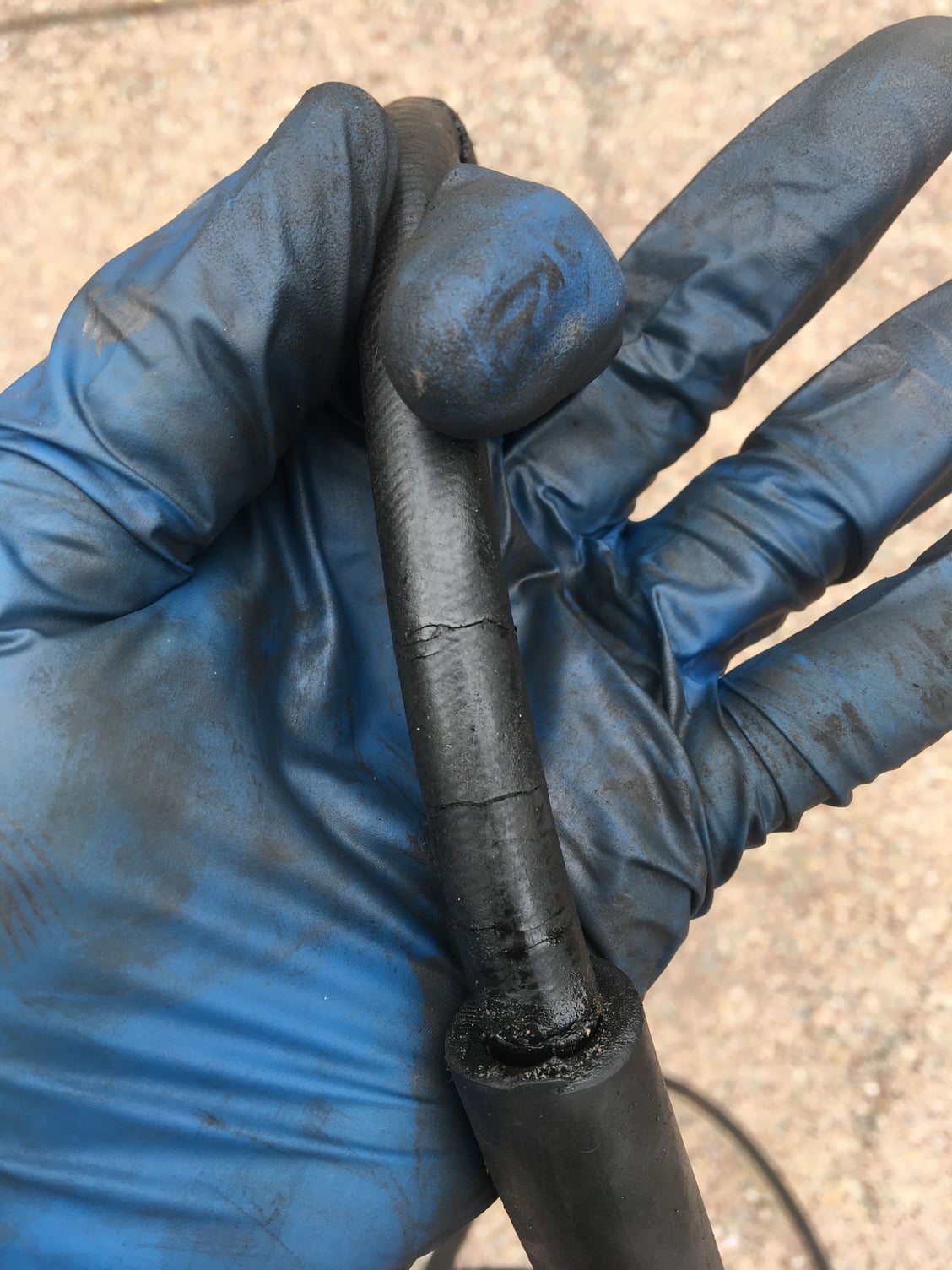
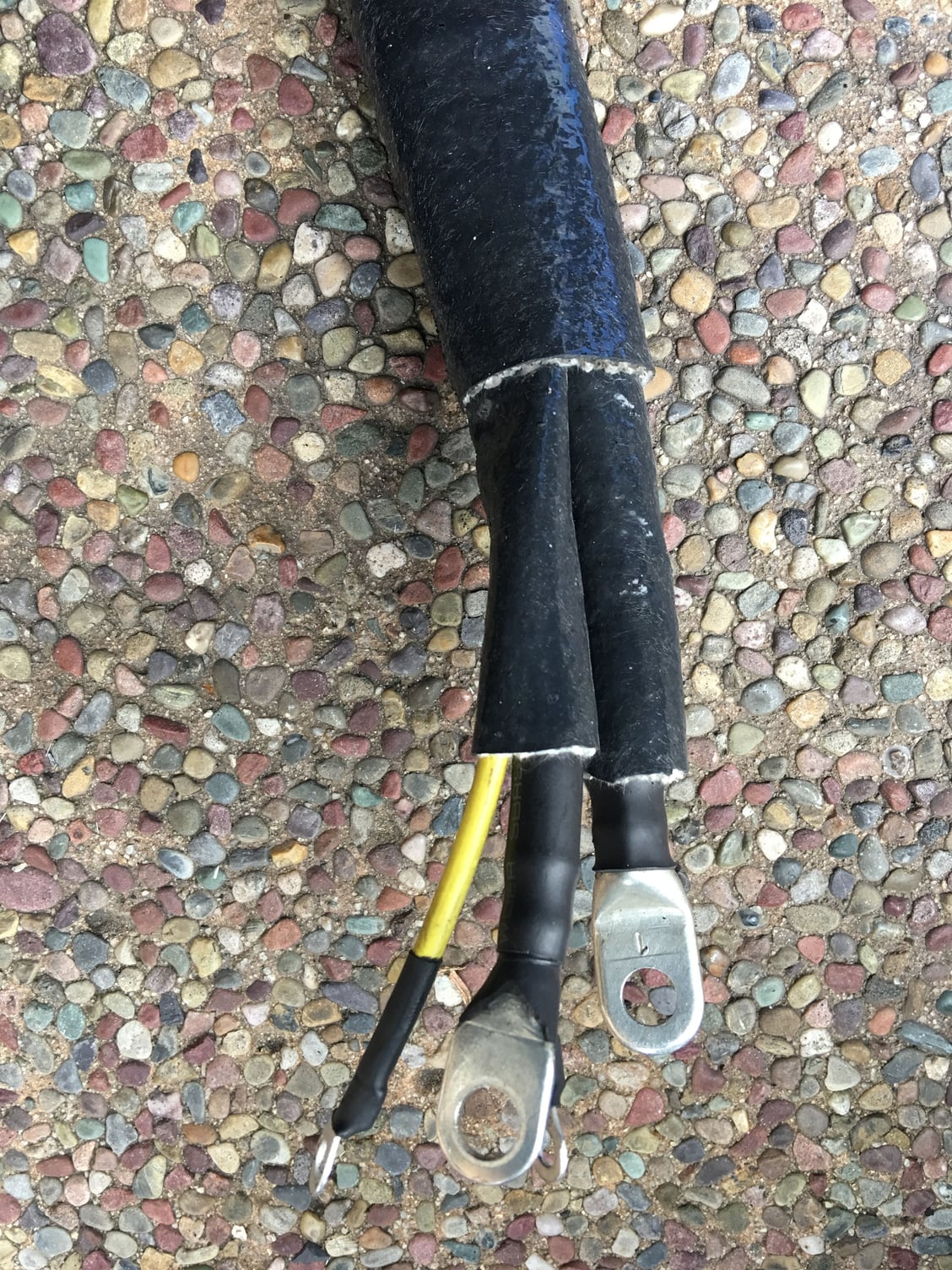
I was really on the fence about this project because the old cable �seemed� ok, but am SO glad I got the old one out. It was time. Check out the cracks and wear, below. The insulation was either dry, inflexible and cracked - or soggy with oil and cracked, especially the 180 loop at the starter. I�m especially concerned by the poor condition of the insulation under the P-clamp on the crossmember. The wire is contorted by the clamp there and any exposed wire could be an absolute disaster.
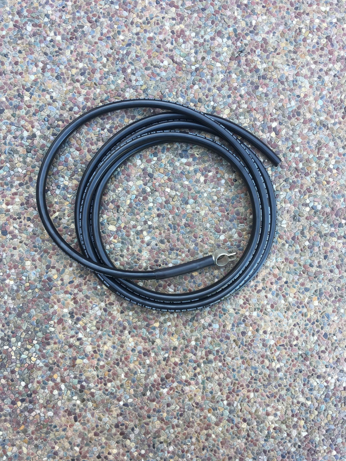
I have the new Ancor 1awg cable waiting, and soldered on a battery lug and sealed with adhesive shrink-wrap. Am debating now on whether to use PVC sleeving per original or maybe try a newer, silicone fiberglass sleeve on the cable and also on Sean�s harness (where I waited to install the starter end until I do it and the new battery cable together). Or maybe a combination of both. The disadvantage to using the original style thickwalled PVC is the distortion of the cable in between the sleeves at the P-clamp as shown in the original.
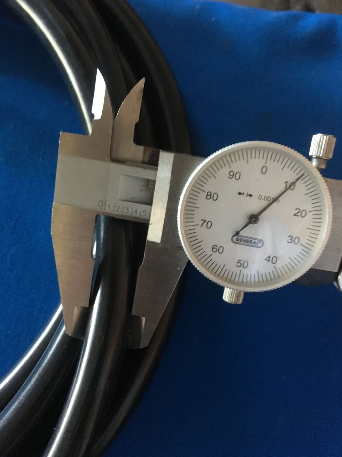
Got it out, yay! Some of the hold-downs, plus the front driver�s side shield. Original cable diameter varied .495 to about .503 Length about 11�2� (without bends would be slightly longer) Cracked and warped insulation under crossbar P clamp in between the two sleeves
Insulation at the 180 bend near starter
New Ancor cable Only slightly larger and still fits fine in the plastic hold-downs
Got my new Ancor 1 awg cable installed today, at least most of the way. I soldered on the battery terminal first, shrunk on some hot glue heat shrink, then put on a nine-inch section of 1/2” pvc flexible sprinkler pipe from Home Depot per Dr Bob’s suggestion.
I first re-installed the large grommet exiting the battery box, coated with Molykote silicon grease. Leaving the starter end of the cable untrimmed, I fed in the cable through the battery box, over the rear swaybar, and through the hold-down tabs for all the rearmost hold-downs. I also put the battery in the box and clamped on the positive terminal (for proper positioning of the cable).
I then spent the next two or three hours flat on my back working back to front to re-install the plastic hold-downs, making sure they were in firmly, then carefully bending the tabs back in place. Oh, and installed the cable in its special builtin channel forward of the rear wheel and used a wood block to bend the lip of the channel back into place. The wood block keeps it from getting wavy.
A couple of things that I changed:
- I did not use the two big pvc protectors at the front as it goes around the bend to the crossmember. I don’t want to mangle the cable the way the stock cable was all bent up there due to the hold-down in the gap between the thick pvc sections. Instead, I placed the entire length of the cable from the last plastic hold down inside a half inch TechFlex “FireFlex” siliconized, fiberglass insulating sheath https://www.techflex.com/high-temperature/fireflex.
- Likewise I didn’t use the big pvc protector on Sean’s new harness around the power steering area, which is already protected by its own siliconized sheath. I checked with Sean and he recommended that the original style pvc not be used with his harness. I figure nothing wrong with belt AND suspenders though so from the point where the cable and harness meet, to the starter, I placed everything inside yet ANOTHER FireFlex sheath, 1”. Fit was a bit tight, but I got both the cable and harness through. Used exactly two feet.
- The original P clamp on the crossmember holding both harnesses is now, what with larger gauge cables and the sheaths, not big enough. I’ll replace it with something slightly larger and will try to find another “stock” p clamp of a larger size.
- EDIT: I also very slightly modified these plastic hold-down blocks. I noticed during test fitting on unused scrap cable that some of the blocks had a very sharp edge just at the lip of the rounded area contacting the cable. I don't know if that's a feature or a bug, but it was pretty sharp and it left a visible line (though not actually a cut) in the insulation of the Ancor cable. Of course, with the very slightly larger diameter of the Ancor cable over original, the last thing I want is a sharp plastic edge digging into and potentially cutting into the cable insulation over time. I used some sandpaper draped over a dowel to gently remove that sharp lip on the blocks. I didn't need to or want to enlarge the hole at all, just enough to remove the lip. It's easy to feel when the lip becomes smooth. With that, the cable is a snug but not overly tight fit and seems just about perfect.
Finally, after test fitting and measuring everything, I trimmed the cable to appropriate length, crimped on a heavy duty lug, and shrunk down some glue-type heat shrink tube.
I’ll wait to get a P clamp installed and finally finish up the starter connections.
I don't believe that for a moment...
Any car is never "done", and the 928 is no exception!
LOL! Yes, the 928... the gift that keeps on giving!! :-)
Definitely need an asterisk on that that I�m only �done� with this one project... which itself grew way beyond its original scope lol!!!
I actually have two or three more projects already planned, including new shocks (and a transplant of �84 adjustable front springs) to cure settled springs and avoid hitting the spoiler quite so often, new bulbs in the pod to replace the dim originals and odo gear fix, and eventually new motor mounts and rack bushings which seem ok but are also all original! But for now, it�ll be FANTASTIC to get back on the road after six months!!!!
... new bulbs in the pod to replace the dim originals ...
I can recommend the 8.5d offerings from SuperBrightLEDs.com for the little indicators, as long as you don't put one in the turn signal spot on a '78. (strange Porsche wiring on the '78 only, reverses polarity depending on which direction is selected.)
Nice pretty colors if you match the LED color to the color of the indicator that it's going behind.
Enjoy the fruits of your labor, get out and drive her!
I'm hoping to get mine on the road this summer, even if she'll still be an ugly duckling for now.
Thanks, I'll check those out. My inclination going in is to go old-school and stick with what I've known and loved for the many years that I've owned the car... I would hate to change the overall look & feel, especially of the general cluster lighting. Is there any agreed-upon set of LED bulbs that replicate stock? And it's important that I maintain dimmability (I think I read here somewhere that the LEDs have less or no dimmability). Having said that, it sounds like you're talking about everything BUT the general cluster lighting (just the warning indicators and blinkers?) What did you use for the general cluster lighting, is it dimmable, and how does it compare to the stock look? I definitely need to do my research before making a final decision. Anyway, thanks for bringing that up!
Currently I have a set of LEDs in the main lighting sockets as well, but they are not likely to stay.
The indicators are what I ordered, since all of my little bulb sockets were rusted to the point that they were either completely inop, or at the least highly intermittent. I got one clean enough that I could use it for testing the circuits, but found that the LEDs were available for 50% of buying the sockets from Porsche (listed as bulbs, if you drill down in the parts drawings).
That said, there are options to dim LEDs via PWM instead of reducing voltage, including one kit offered by a member here that uses your stock gauge dimmer wheel.
If I do use LEDs on my cluster, I'm going with a different dimmer option, but it won't look completely stock, so it's not for everyone.
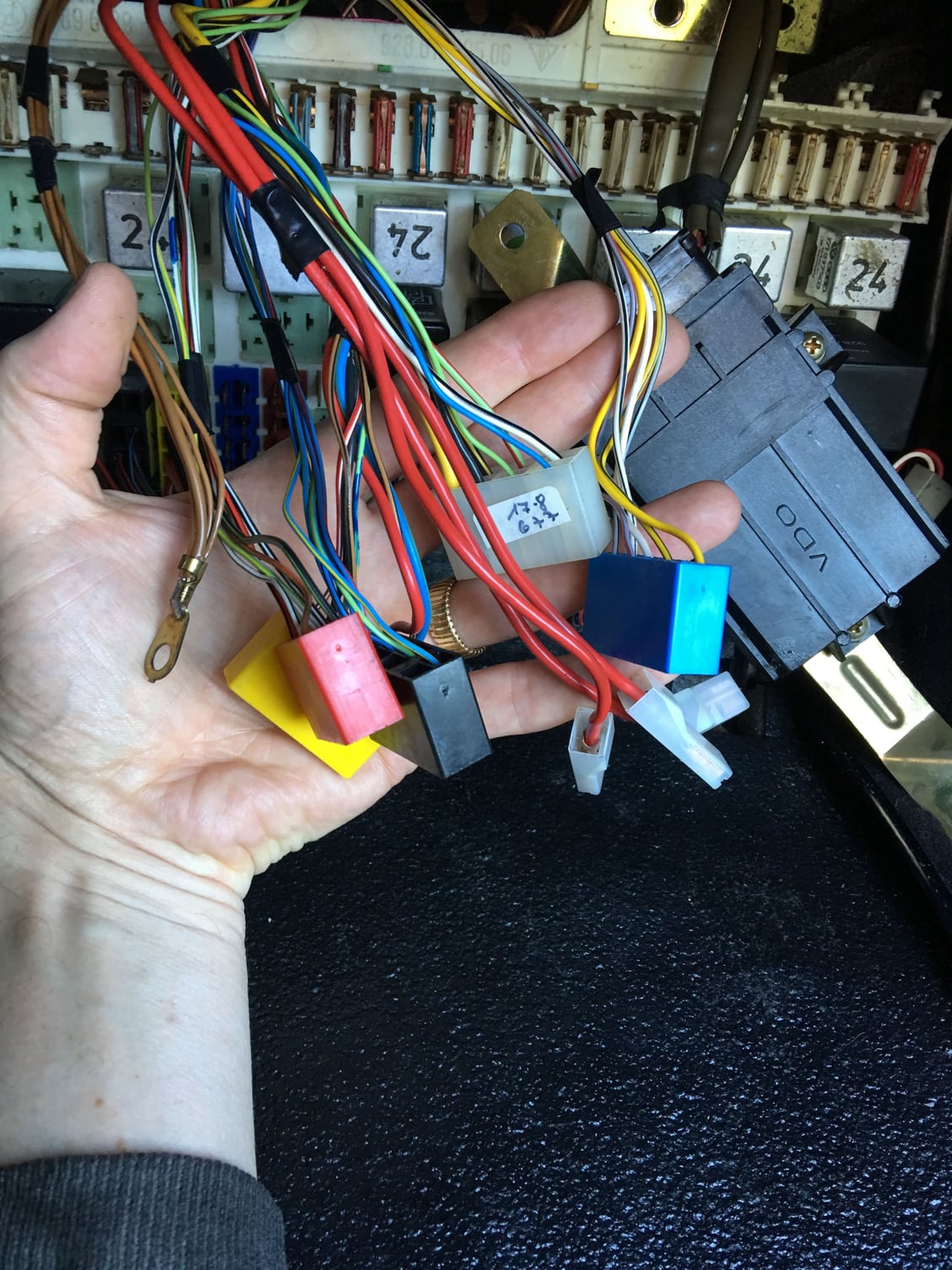
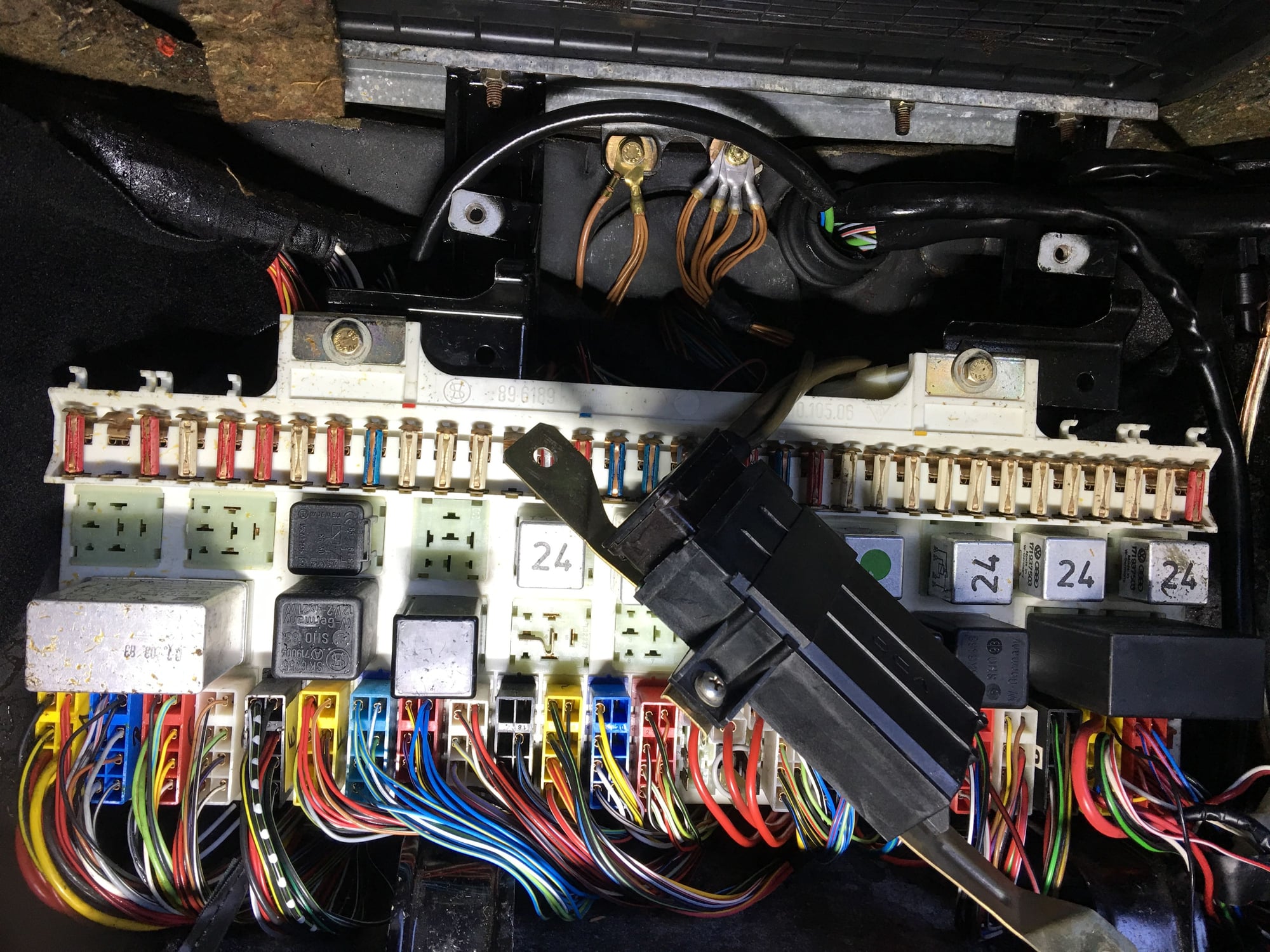
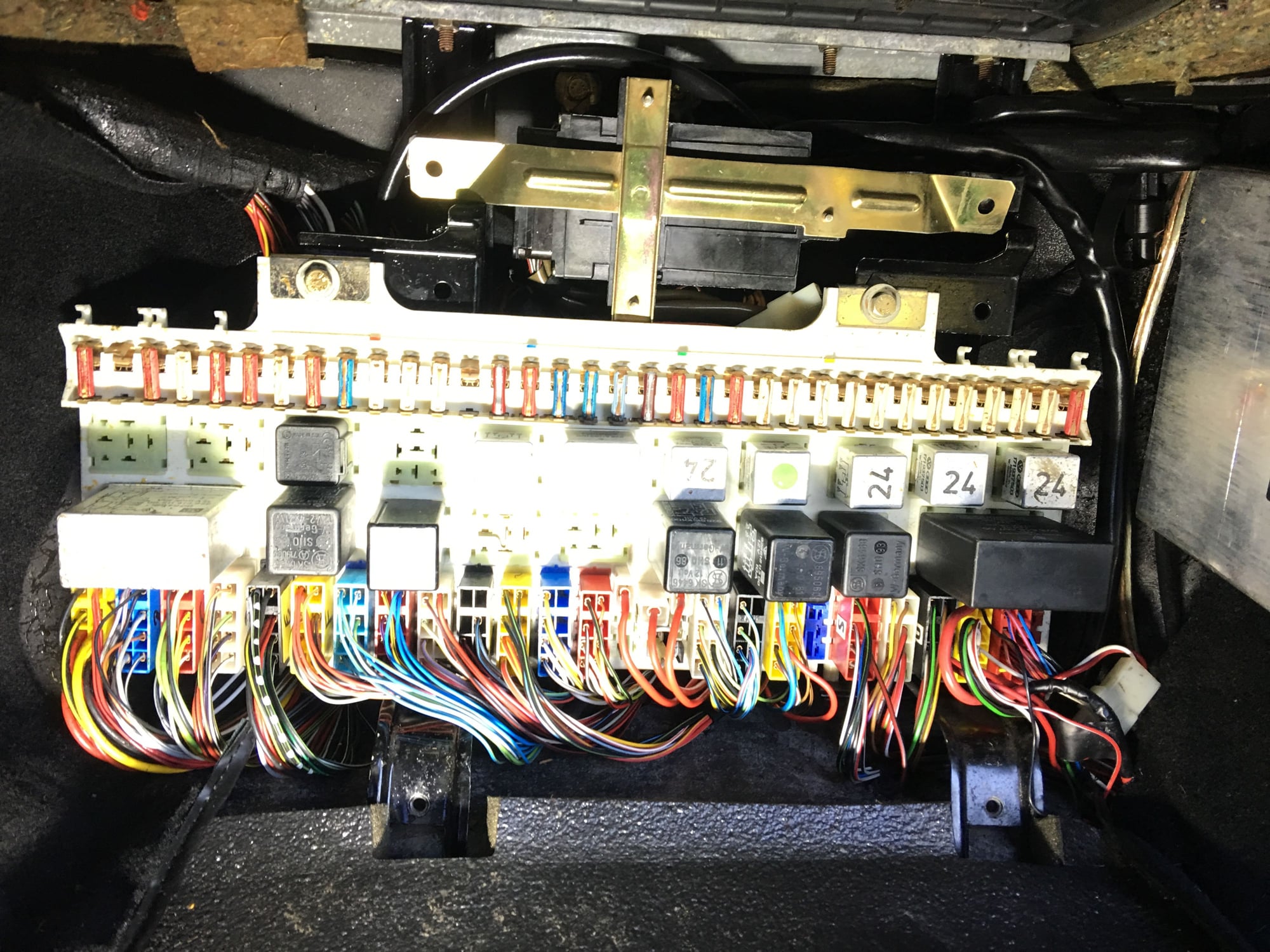
Made a little more progress after work this evening in getting the engine compartment harness all plugged in at the central board. The Porsche harness fit in perfectly and has been such a joy to install. The lengths of the wire bundles to each colored block are different (and just right), and even the lengths of individual wires within a block are different to allow a perfect 180 degree bend up from below the board to the plug. There is just the right length to feed each connector block behind the existing horizontal loom and down and out the bottom of the panel.
The whole wiring maze behind the central panel seems like a jumble, but it’s actually pretty methodically organized. My goal was to simply put back the new wires exactly the way the old ones were routed and then get the heck outta Dodge!
I had taken some photos of the ground points above the board prior to disassembly and am glad I did. I also zip tied together the ground wires remaining behind going to each ground point and glad I did that too or I would have missed one. I referred back to the photo to get the spades at the ground fanned out and in the same orientation as they were before, as well as which were flipped back-to-back. I put just a drop of DeOxit on them as I reassembled.
EDIT: I should also note that, while most of the colored plastic connector blocks slid right into place the first time, one of them gave me some trouble. It just didn't seem to want to fully seat all the way down in its slot even though it was almost all the way in. It turns out that the top left spade connector (viewed as you push the connector on) was not mating with the spade on the board properly. Upon closer inspection, that upper left spade on the board appears to have some kind of doubler on it, and was thicker than the others. It had pushed the female spade slightly out of its locking tab in the connector. After reseating the female spade, I just started the connector on at an angle to engage the upper row of spades first, then rotated down to engage all the others. At that point it went on smoothly and engaged fully. Just in case, I double-checked all the other individual female connectors in all the connector blocks (visible facing you from the backside of each connector block) to make sure that they were all fully engaged (they were).

 05-20-2019, 03:47 PM