When you click on links to various merchants on this site and make a purchase, this can result in this site earning a commission. Affiliate programs and affiliations include, but are not limited to, the eBay Partner Network.
Hello fellows! Well, here I go. Dropped the fuel tank expecting to find a gooey mess after a 20-year hiatus. It wasn't gooey but a mess it is.
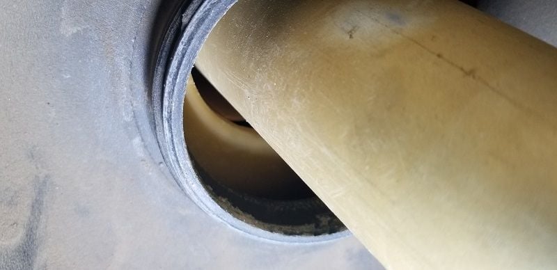
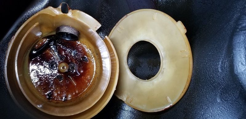
I tried to remove the sending unit to be able to clean the tank. The ring in the picture gets in the way. How do I get the unit to come out?
Next, I figured that I would remove the hex piece at the bottom of the tank to try and see if there was anything I could do to remove the sending unit. I have read several posts regarding the removal of the tank, including Duane's post ( I realize his is/was a later model) and someone else's with a '79 but neither mentioned any issues removing the sending unit or the hex thingy at the bottom of the tank. I do have a manual but there is nothing about these components. Talk about a sparse manual!
Anyway, DISASTER strikes!
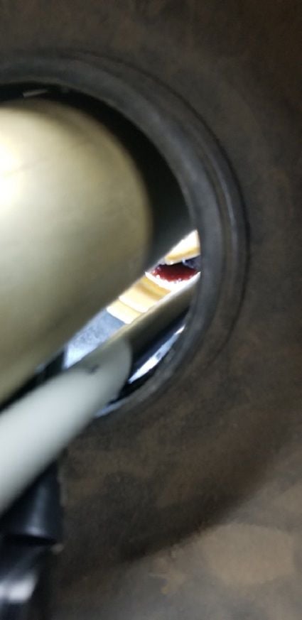
Here you can see the inside of the tank. No sign of varnish whatever. The wine looking liquid is what is left of the fuel.
So, how do I remove the sending unit?
What about the lower piece? Is that a secondary fuel pump? How do I remove it?
Any help you can offer will be greatly appreciated. I have a feeling I will be saying this for a long time to come.
Thank you,
Mario
Mario,
The sending unit is at the top of the tank under the black round cover under the carpet in the hatch.
What you are trying to remove appears to be the intank pump that "primes" (for lack of a better term that immediately comes to mind) the external fuel pump.
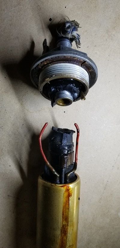
It appears that the internal pump has come apart and the threaded male part of the pump is still embedded in the female threads that are made into the tank. Do not attempt to unscrew those threads without using copious amounts of PB Blaster on the threads first. In addition, I think some folks have used a large hose clamp to keep those threads from coming loose from the tank. Once those threads are loose and unscrewed from the tank portion, you will be able to remove the internal pump.
If you do happen to loosen the threads from the tank, Roger@928sRus has a product that can keep you from having to buy a new fuel tank.
John, thanks for the information.
"It appears that the internal pump has come apart and the threaded male part of the pump is still embedded in the female threads that are made into the tank."
Ok, it would seem that male piece would still be attached at the bottom of the tank. To be able to try to remove the male threaded part, I need to gain access to it. Any idea how to pull out the internal pump? The ring seen in the picture keeps it from pulling out. Is that ring part of the male threaded piece? It should not be holding the internal pump as otherwise, how can it be unthreaded without removing the " tube" aka the internal pump? I tried turning the ring hoping there was a specific position where it would drop down but was not successful.
What about the other picture where a rubber hose and electrical wires were severed when I turned the hex head cap at the bottom of the tank? What is that piece called and how do I get that removed?
I doubt this has not been covered. Hopefully, someone who has dealt with them or has other information can chime in.
Thank you,
Mario
Mario, you should be able to go in from the top hole where the sending unit is and fish the remaining part of the internal pump out.
Can you get the sending unit out of the top hole?
In picture 1, is the ring that is stopping you from removing the sender unit the same color as the sender unit tube? Is it attached to the sender unit tube or are you of the impression that it's attached to the tank itself?
If you lived closer to DFW, we could just by and get you fixed up, but 8 hours away is a haul for a daytrip.
Lookup the tank section in PET - page 201-00. The bottom of the sender unit has an off-white plastic cup on it. There is a weir in the bottom of the tank to try to avoid sloshing letting the pump suck air, and sometimes the cup gets caught on the edges of the weir. If you pull too hard you may break the weir or the cup, not sure what the downside is. Try to hold the sender VERY vertical, straight and feel where its catching, and it should come out - this issue is not unheard of. The in-tank pump is screwed into the tank from outside, so that thing in your pic has to come out somehow through the hole- try to locate where its catching, and crimp it a little, maybe with needle nose vise grips. Mostly the in-tank pumps are more trouble than they are worth, unless you are hot and high, and working the car hard - unlikely in a 79. My S did 10 years in Saudi without an in-tank pump.
jp 83 Euro S AT 57k
I have messed with a lot of old gas tanks trying to save them... I learned a few tricks.
Sending unit: (top of tank) see Jpitman2 comment above. The baffle "ring" is stuck to the bottom of the sender but its not supposed to be. This may have been avoided by twisting the sender around a bit BEFORE lifting it. It is supposed to lift right out but gasoline residue that has turned to red honey is essentially "glue" . That ship has sailed here since the baffle ring has lifted off of the baffle base in the bottom of the tank. As jpitman2 said lift the sender straight out, pull hard and the stuck baffle ring will fall into the tank. Its not the end of the world there are plenty of baffle rings floating around in tanks as they drive around for years....but if you have a small friend (child) that is interested in 928s they can reach through the sending hole and place the baffle ring back onto the baffle. *** check local snowflake laws before having a child touch a fuel tank ***
In tank pump/ stainer threads and inserts: This is more challenging, and more tanks get ruined down here by bad methods (ask me how i know) The reason your in-tank pump or (in most cases) threaded strainer did not unscrew is from thread corrosion between steel female threads (on the tank insert) and aluminum threads (on the pump/strainer) a tank that sits gets moisture, water ends up on the bottom of the gasoline, and rusts the steel female threads. The steel section is bonded to the luopene tank from the factory with heat..works great with clean threads, but is not designed for the heavy twisting force required to free rusted threads. The problem that occurs with stuck threads is that you can break the bond on the tank insert and it starts spinning in the tank. There are ways to fix this but it is controversial, some guys say a tank is trash once the insert spins, if you search around on here you'll find that vigorous debate.
Methods tried include lots of penetrant (kroil, fluid film, blaster etc) I have NEVER gotten a frozen insert to unscrew with penetrant. I know others have, but now i don't bother with it. Others have tried clamping a hose clamp around the plastic tank at the tread insert to "grip" the steel insert. Again, success is not guaranteed.
If the steel (female threads) insert is not spinning in the tank yet the 100% success rate method is to use a 1-3/8" hole saw to drill out the guts of the pump or aluminum insert, leaving the frozen threads intact. Then using a hack saw blade, by hand, start cutting wedges out of the remaining parts of the pump/insert along the thread surface.. the idea is to cut down to, but not into, the steel (female) threads, then gently pick out the wedges you cut. Result: pump/insert removed, female insert intact, no rotational stress on it fighting with frozen threads. Now that the threads are exposed you'll see the rust on the inside edge of them (where the water was sitting) and where its hell to get penetrant on them anyway...now all exposed for easy cleaning.
I'll probably start WW3 with this one, but don't bother with an in tank pump on a 79 CIS car, just get the correct strainer and gasket.
As Drooman says! 2 more things to say - I believe, but dont quote me that the screw in tank filter in EARLY tanks was a different size from those available now and is NLA - if and when you get the in-tank pump out, measure the diameter of the thread so you know not to waste time. The numbers that come to mind are 36mm vs 37mm.
I spun the threaded insert in my tank, and since I did not have time to play around (was about to export the car out of Saudi), I covered the whole area of the filter alloy section with PC11 epoxy, and it never leaked a drop in 5+ years, so it can be done.
jp 83 Euro S AT 57k
I was headed to the same conclusion as Drooman about that ring on the sender unit. It should just slide off and drop to the bottom.
I do believe that once you get the sender out of the way, you should be able to lift the remains of the intank pump out through the top to get IT out of the way.
And as Jpitman posts, the early model tanks had a smaller size diameter, so measure it once you get it clear of the debris.
Thank you to Drooman and Jpitman for posting and clarifying.
Last edited by soontobered84; 08-15-2018 at 12:01 PM.
Reason: add
Just rip out the old pump, with the insert, and buy the new threaded insert i made from Roger and enjoy all the benefits of having the modern threads in the tank
That inside pump had to go in through the factory insert. By the picture, that insert is still in place correctly. Grab the end of the hose, the one with the Oetiker clamp on it, with needle-nose and work it through that insert. It went in, because there's no practical way to crimp that clamp on there from inside the tank. It -may- have been possible to crimp the other end of the stub connecting hose from inside, but I think the plastic baffle insert blocks access that close to the outlet nozzle in the tank.
the short hose and the silver clamps are shown under the red wire. That's what shows in your picture #1
Dr. Bob,
Since the outer part of the pump is the only thing that holds the internal pump into the tank, with the outer part gone, the internal pump should be able to be removed through the top hole in the tank once the sensor has vacated that spot. I believe that the threads for the outer part of the pump are still intact and present on the threaded insert portion of the tank, which would keep the internal pump from exiting the correct and bottom hole of the tank.
Mario, If the threads are not still present, it is a tight fit and it must come out straight, but remove the internal pump from the bottom hole (picture #1)
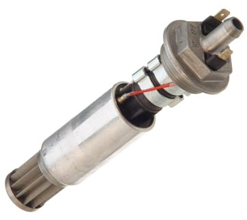
Mario, Here is a picture of the internal pump so that you can see how a complete one appears and what you are dealing with.
"Lookup the tank section in PET - page 201-00" I assume this is a parts manual, which I don't have. I bought a manual on a cd from someone named Jim Wassel (he may be known to the members of the forum) and I seem to remember that was supposed to be included in the cd but I have not been able to find the PET in it. Anyway, if it is available online, please let me know.
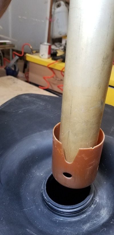
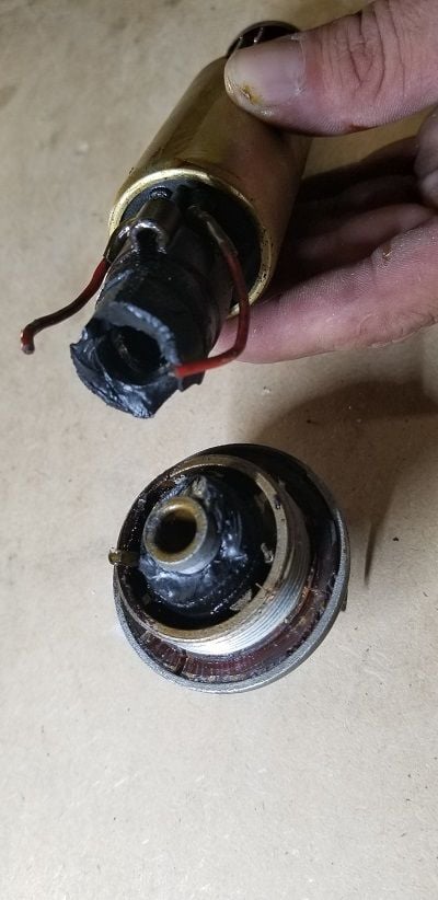
The top of the cup had flared out.
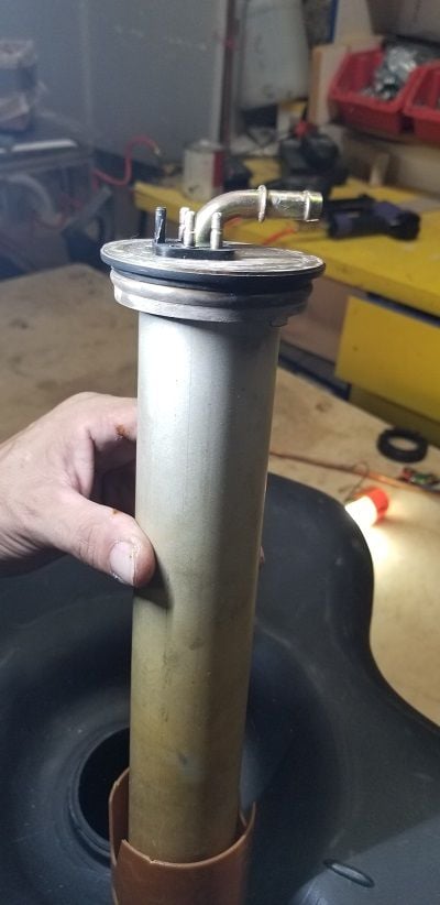
Well, thanks to your encouragement, I gave it another go at it, this time with another pair of hands and we were able to get the "tube" out! The cup at the bottom of the "tube" had flared out and that is what was preventing it from coming out. For some future soul's reference, we lifted the "tube" out and while my helper compressed the plastic "wings" of the cup with a couple of thin, long screwdrivers, I rotated the so called tube and we were able to get it out. Here are some pictures to make it easier to understand. Not knowing what it looked like made it more difficult to figure out.
There is what I called the ring on the right, which prevented the "tube" from coming out. Fortunately, the old gas was in a gooey state and it was easily dissolved with a locally sourced water based degreaser. I will get a toilet brush (long handle) to scrub the few sections with the "jelly", then will pressure-wash as necessary. As can be observed, the bottom of the tank looks pretty clean. There must have been very little fuel left when first parked.
The internal pump pulled out easily. It must have been glued on/to the bottom and it broke when I first turned it.
What I have been calling the "tube"
So, is this repairable? I would probably fix it, if I could. Leave it out if not practical to fix?
But maybe I am getting ahead of myself. Look at what happened to the threads where the internal goes. Is that what improved threads BauerR is talking about? Because I would jump on that. If not, could that be epoxied, plastic or JB welded? Hoping is not beyond repair.
Jeez!
Again, thank you all so much for your generous contributions to this thread. What a great learning experience. I am feeling a lot better already!
Mario
You'll need a new bung with the wires intact, at minimum. Roger sells that, along with the Greg Brown-recommended hose and new clamps. The piece that BauerR makes (also available through Roger) is the threaded insert that's normally molded into the tank nozzle. In stubborn cases the nipple has bonded with the insert, so turning the nipple to get it out draws the insert out of the tank nozzle with it. The repair piece goes in via the tank sender hole in the top, and is drawn into the nozzle. It's an ingenious design and saves you the cost and effort of sourcing a replacement gas tank.
The inner pump is needed in any warm to hot climate. The fuel system circulates through the engine bay via the bypass-style fuel pressure regulator and that return line that connects at the level sender. Fuel gets hotter as it passes through the engine, and on hot days it will start to boil in the fuel pump inlet especially when tank level is low. The system functionally vapor locks between the tank and the pump and the engine stops, starved for fuel flow. The in-tank pump is a spendy piece, but it's essential for hot-day driving in my experience. If you get talked into doing away with that pump, you'll want to look carefully at the outer pump to be sure it is up to the task with low suction head.
Couple more points. While the sender is out, dismantle and clean it . At least test its functionality by connecting its lead and seeing what your gauge reads as you tilt the sender from vertical to upside down - should go from empty to full. Tanks left to dry out typically get fuel residue on the wires and read wrongly or not at all. Undo the small nut on the bottom etc - see here https://members.rennlist.com/sharksk...ugeGremlin.htm and other pages here should help you. Make sure the wires are rubbing on the pointy side of the float contacts , like this > , not like > , which mine was. Take care, the wires are fine. Resistance with float at bottom should be ~ 80 ohms IIRC.
If thats a crack I see in the area of the outlet on tank bottom where the pump came out, I suspect your tank is done for.
Being as your 79 will be a 240hp 4.5L its not going to need as much gas as the later bigger engined models. Once you have a tank sorted out you will need to choose your pump set up. To reiterate , my car (83 4.7L S) did the best part of 8+ years in Saudi (up to 120F in summer, and 3000ft ASL) with a single external pump (C16 UK spec car), the last few years with an S4 pump, which in theory is wrong for a CIS car, running 75psi fuel pressure, without fuel issues.So, I dont believe a second pump is mandatory, as long as you have one UNDER the tank. If you go with a single pump and get problems, there is no cost penalty involved in adding the in-tank pump later. All cars had wiring looms ready for an in-tank pump, and if not fitted (as in mine), they just wrapped up the wires out of the way - found them when I replaced my tank for the spun insert.
PET is available on the web free from Porsche - at least it was when I installed it. Do a search here for PET download or PET install .
You might need a new 'gasket' - rubber seal on the top of the sender unit; heat the plastic nut that holds the sender in place in hot water when reassembling.
jp 83 Euro S AT 57k

 08-13-2018, 09:19 PM