
86.5 CE wiring help
 04-12-2018, 11:17 PM
#1
Burning Brakes
Thread Starter
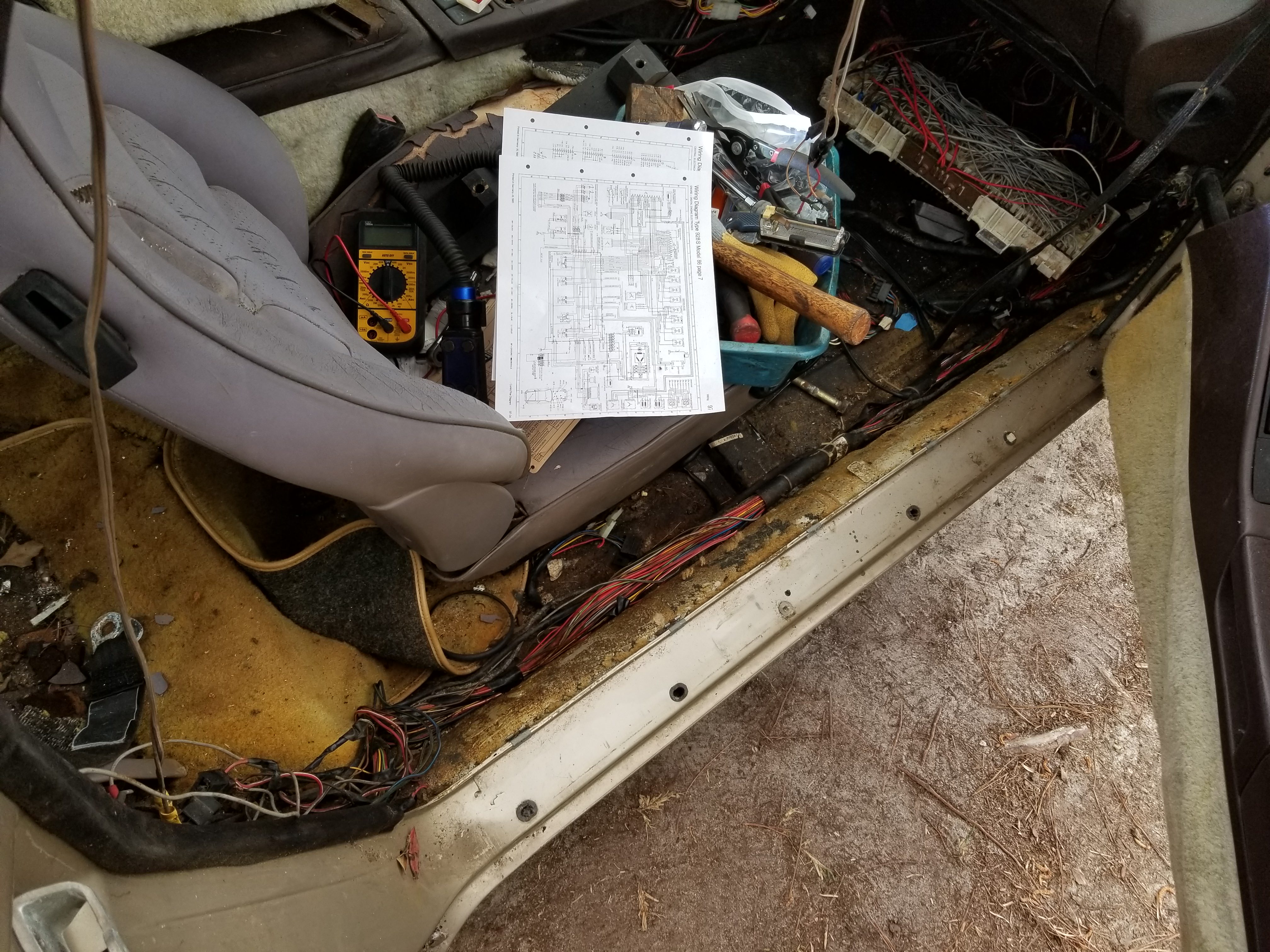
I'm trying to figure out some strange/modified wiring in my CE panel and figured it might be best to start a new thread for that.
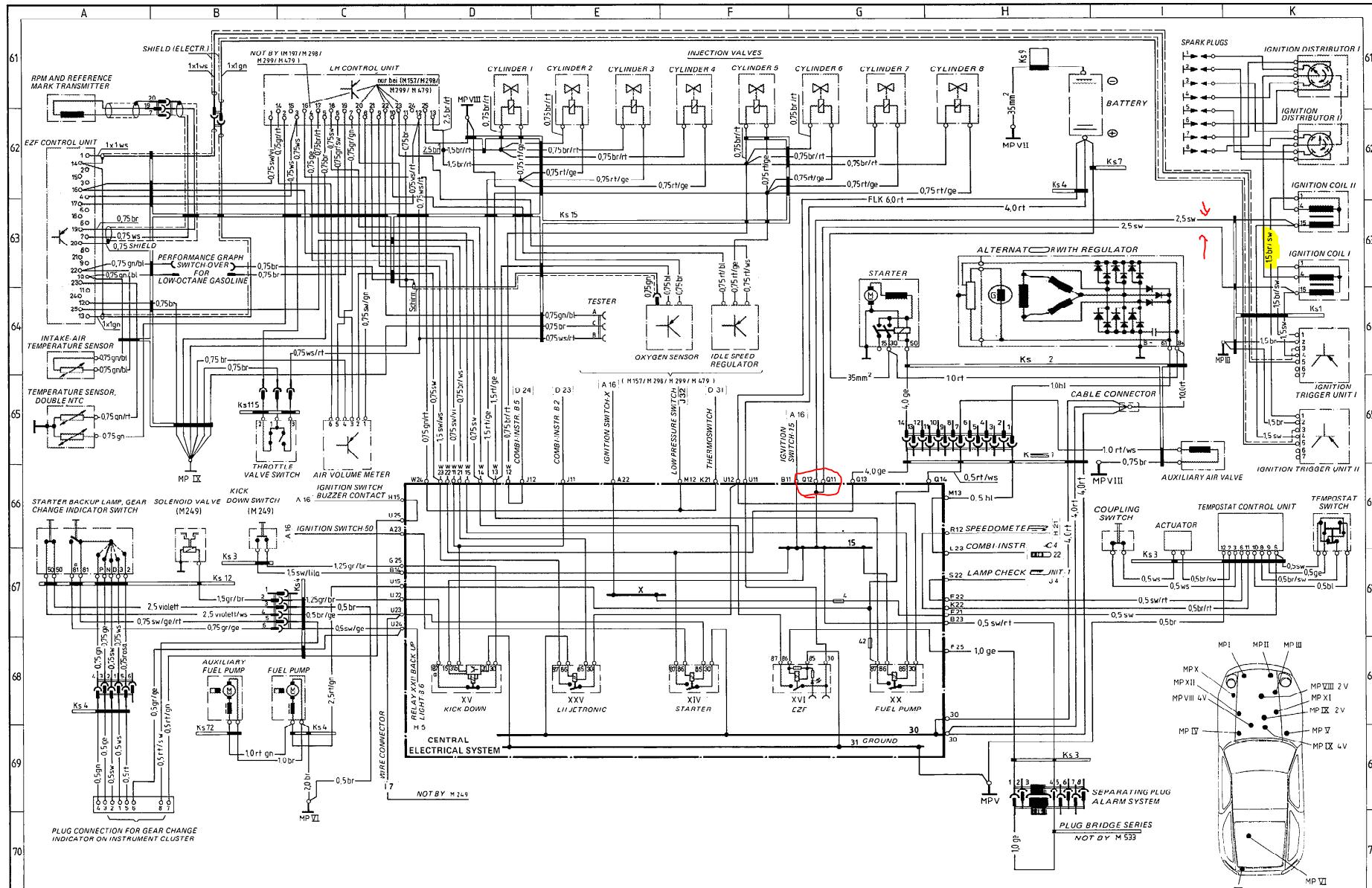
Been going off of this diagram: http://www.ligeti.com/928/Porsche%20...20-%201986.pdf
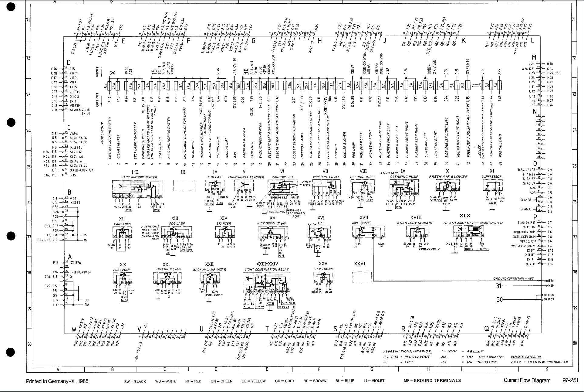
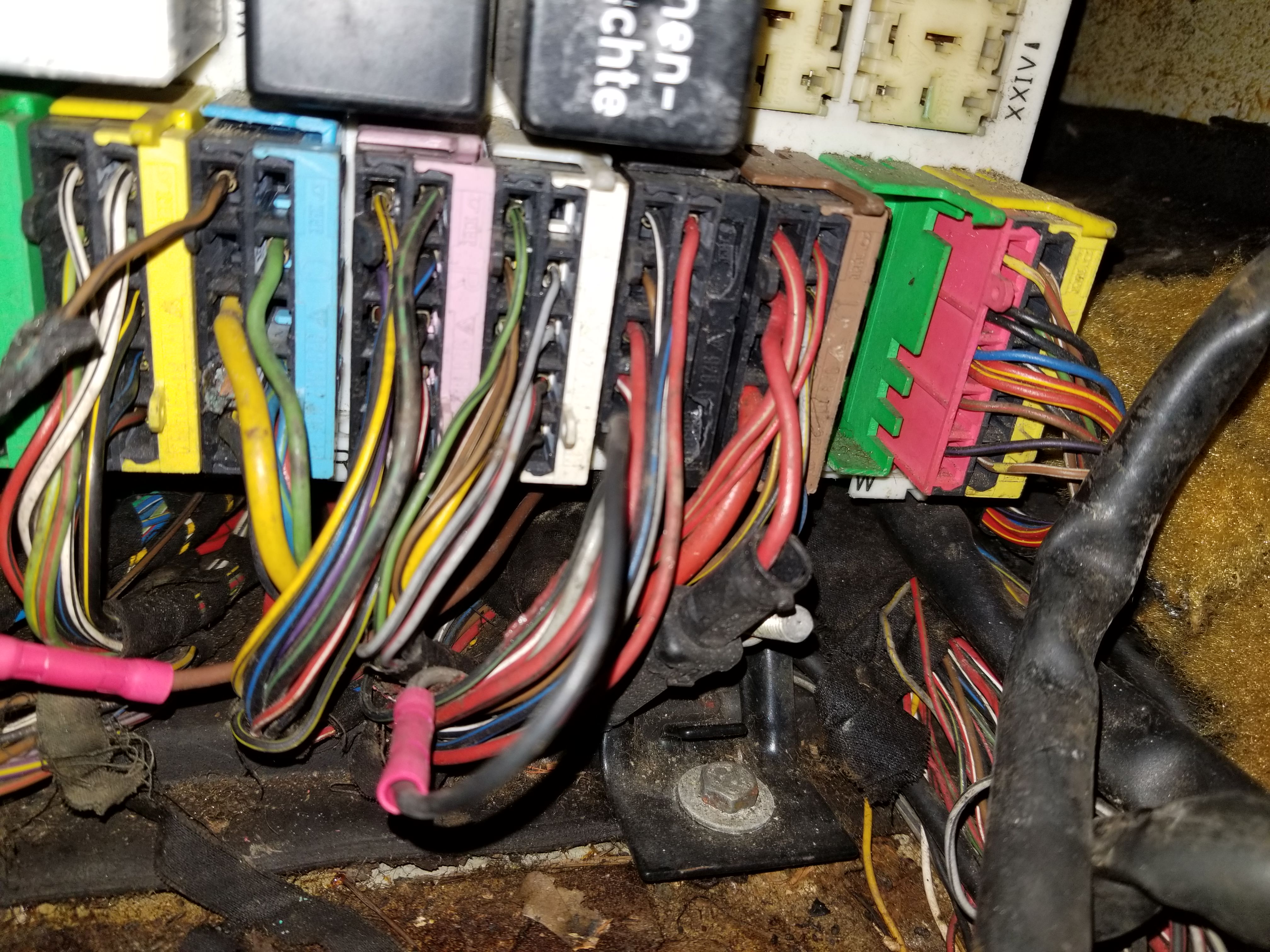
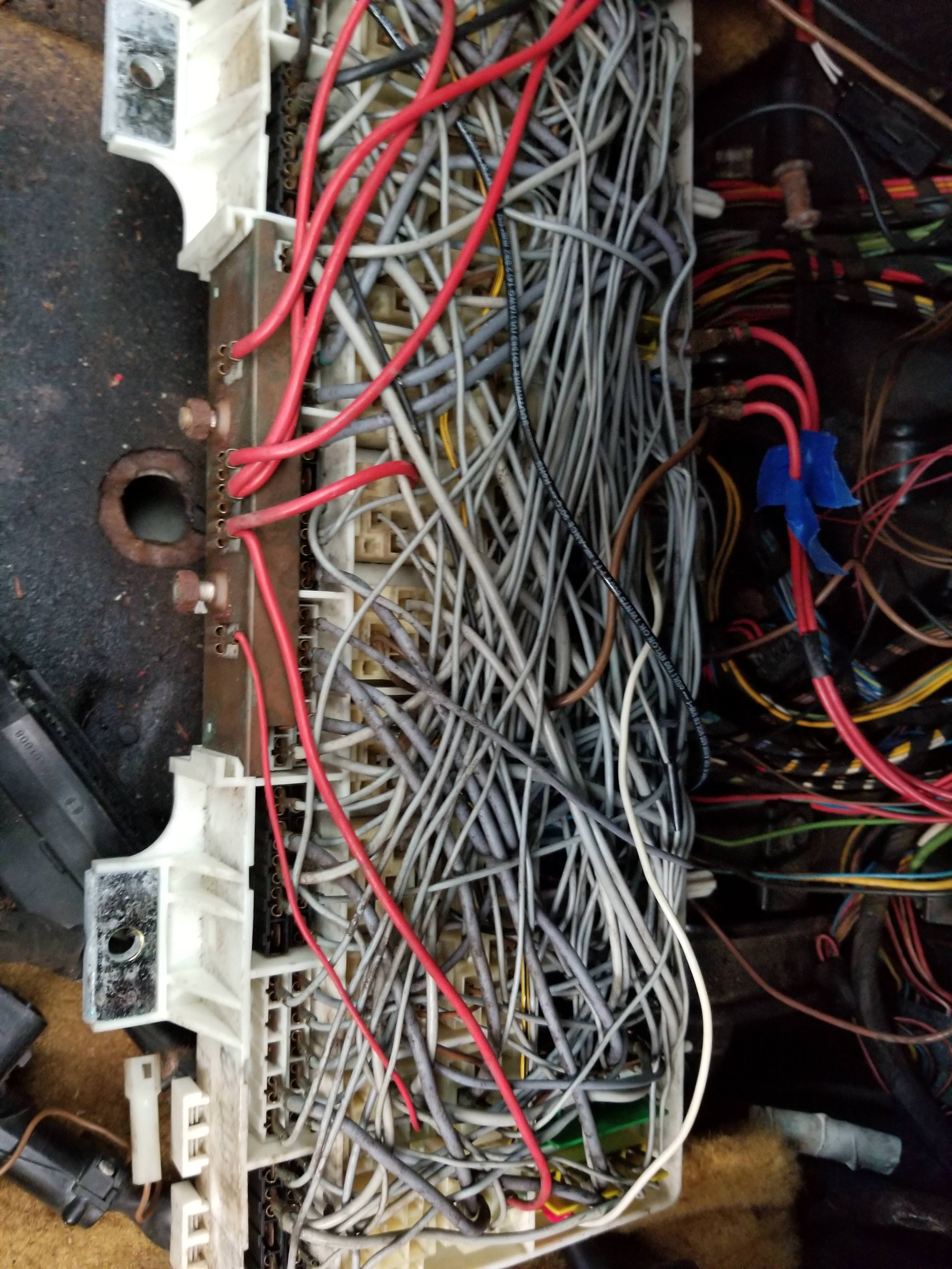
The black wire going across the back of the CE panel is going from fuse 9 (phone) to the blue connector socket (Q) pin 11 as it should. There is a wire on the connector going off somewhere. I doubt this car has a phone, but who knows.
Attachment 1350877
Attachment 1350878
The wire that's cut off that same Q connector in pin 12 looks like it's supposed to go to fuse 7 for a seat heater. Not sure if the car even has that. Just has two 4 way rocker switches on each seat.
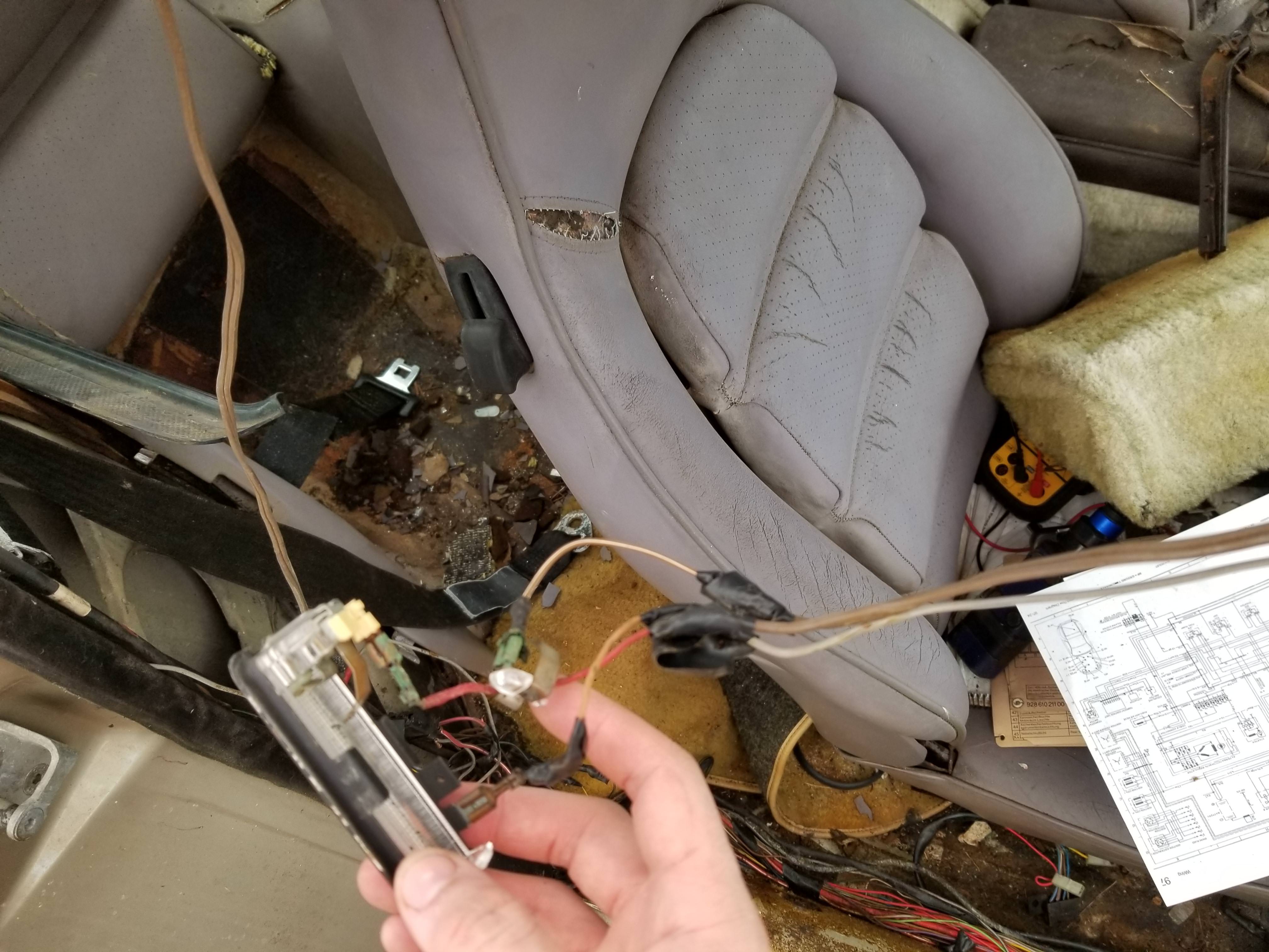
Now where I'm getting a bit baffled is that brown wire in pin 15 of the Q connector. The diagram shows Q15 as connected to S14 on the top (of the diagram) and F23 on the bottom. Connector S pin 14 shows that it's connected to Q15 as well, but F23 doesn't. I'm pretty sure I'm looking at this diagram wrong here. Either way, that wire appears to have been cut and is dangling under the panel.
Attachment 1350879
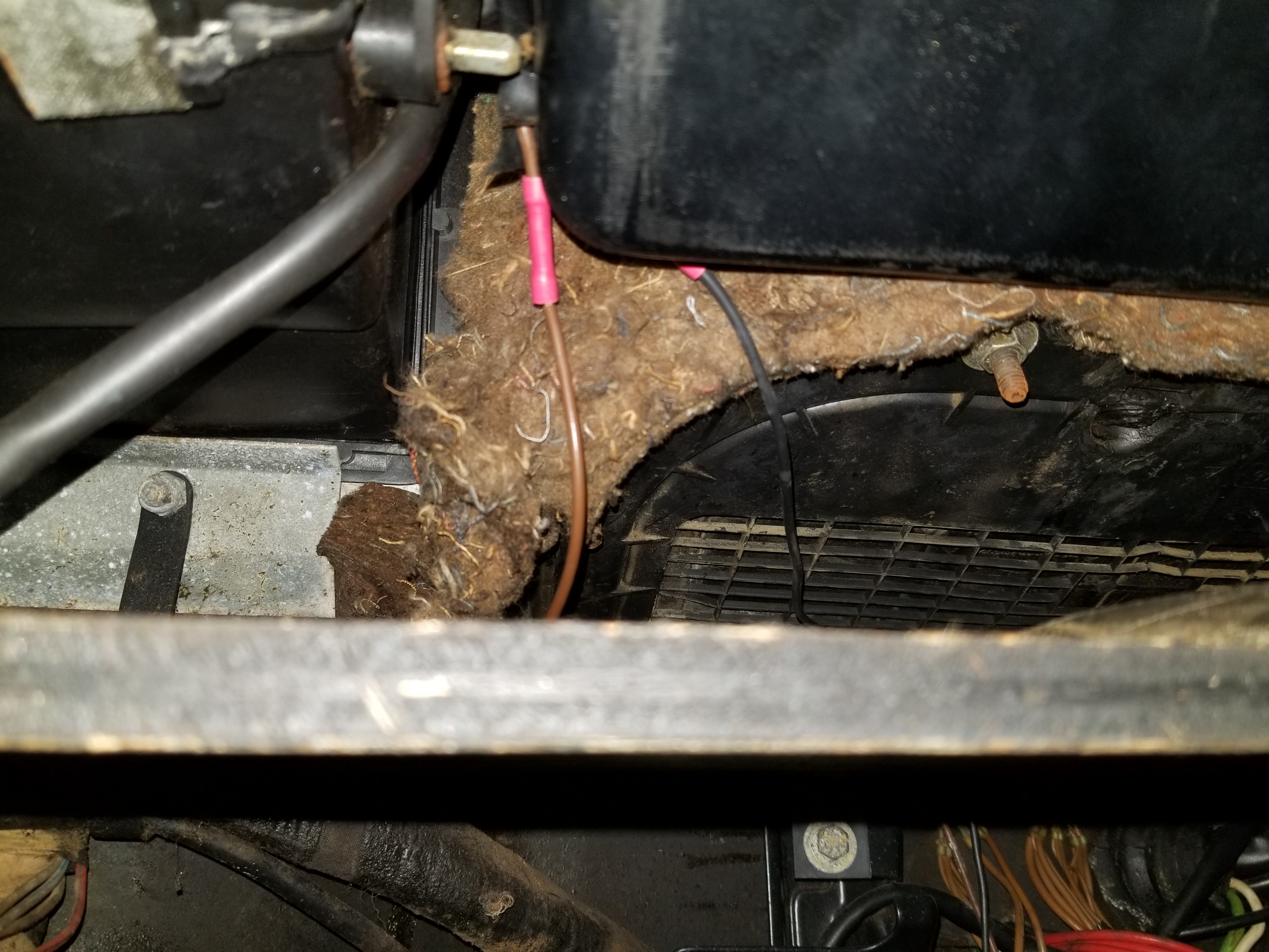
The thick brown wire that has been spliced in with that butt connector goes to a factory looking pair of wires (brown and black) behind the glovebox. That black wire then goes down to feed fuse 6 (lamps keyboard light switches time delayed relay interior light) in the above photo, so I really have no idea what that pair of wires is for.
The other butt connector is in connector T pin 11. I don't see another place where that original grey wire would go. Again, I don't think I'm understanding the diagram. It shows T11 connected to E23.
Hopefully that rambling made some sense. If not please let me know.
-Matt
Been going off of this diagram: http://www.ligeti.com/928/Porsche%20...20-%201986.pdf
The black wire going across the back of the CE panel is going from fuse 9 (phone) to the blue connector socket (Q) pin 11 as it should. There is a wire on the connector going off somewhere. I doubt this car has a phone, but who knows.
Attachment 1350877
Attachment 1350878
The wire that's cut off that same Q connector in pin 12 looks like it's supposed to go to fuse 7 for a seat heater. Not sure if the car even has that. Just has two 4 way rocker switches on each seat.
Now where I'm getting a bit baffled is that brown wire in pin 15 of the Q connector. The diagram shows Q15 as connected to S14 on the top (of the diagram) and F23 on the bottom. Connector S pin 14 shows that it's connected to Q15 as well, but F23 doesn't. I'm pretty sure I'm looking at this diagram wrong here. Either way, that wire appears to have been cut and is dangling under the panel.
Attachment 1350879
The thick brown wire that has been spliced in with that butt connector goes to a factory looking pair of wires (brown and black) behind the glovebox. That black wire then goes down to feed fuse 6 (lamps keyboard light switches time delayed relay interior light) in the above photo, so I really have no idea what that pair of wires is for.
The other butt connector is in connector T pin 11. I don't see another place where that original grey wire would go. Again, I don't think I'm understanding the diagram. It shows T11 connected to E23.
Hopefully that rambling made some sense. If not please let me know.
-Matt
 04-13-2018, 12:08 AM
#2
Burning Brakes
Thread Starter
I've also noticed that the electric locks, brake light, and window fuses appear not to have a power wire running to them. The locks (lock switch on dash lit up) and windows didn't work when I hooked power up yesterday, but the brake lights did.
04-13-2018, 02:07 PM
#3
Rennlist Member
First thing I'd do if trace all unknown wiring, if not needed, pull it.
Next would be to fix one circuit at a time, replacing any burnt wires w/ correct gauge and correct size fuse to protect the wiring.
The biggest issue with the CE panel is the connection (fuse, relays and jumpers) get oxidized over time from dampness or a leaking HVAC Fan seal.
WD40 can help with that, try to avoid sanding it removes the plating if any is left on the contacts and will oxidize even quicker.
So from what you are saying several circuits are not working, take them one at a time, Brake lights, and any tail lights can be the Lamp controller located on the right side of the parcel tray.
I have one car that the wiring was so cut up I replaced it ALL w/ used harnesses.
Dave K
04-13-2018, 02:34 PM
#4
Rennlist Member
Join Date: Feb 2016
Location: Stafford, VA
Posts: 54
Likes: 0
Received 0 Likes
on
0 Posts
If you haven't pulled your dash yet, now might be a good time. It will help a lot with tracing all those wires. There are a lot of wires running behind there to the dash and the center panel. It doesn't take long to pull the dash and it will give you a lot more room to work. At that point you'll also have access to the alarm system computer (if so equipped) which can cause headaches as well. You'll also want to pull that HVAC recirculating flap assembly and fan situated above the CE panel since they have a tendency to leak when left sitting outside for several years.
04-13-2018, 11:20 PM
#5
Burning Brakes
Thread Starter
Ok, so I traced where those two unknown wires were going. They go up through the firewall and to what seem to be called ignition trigger units.
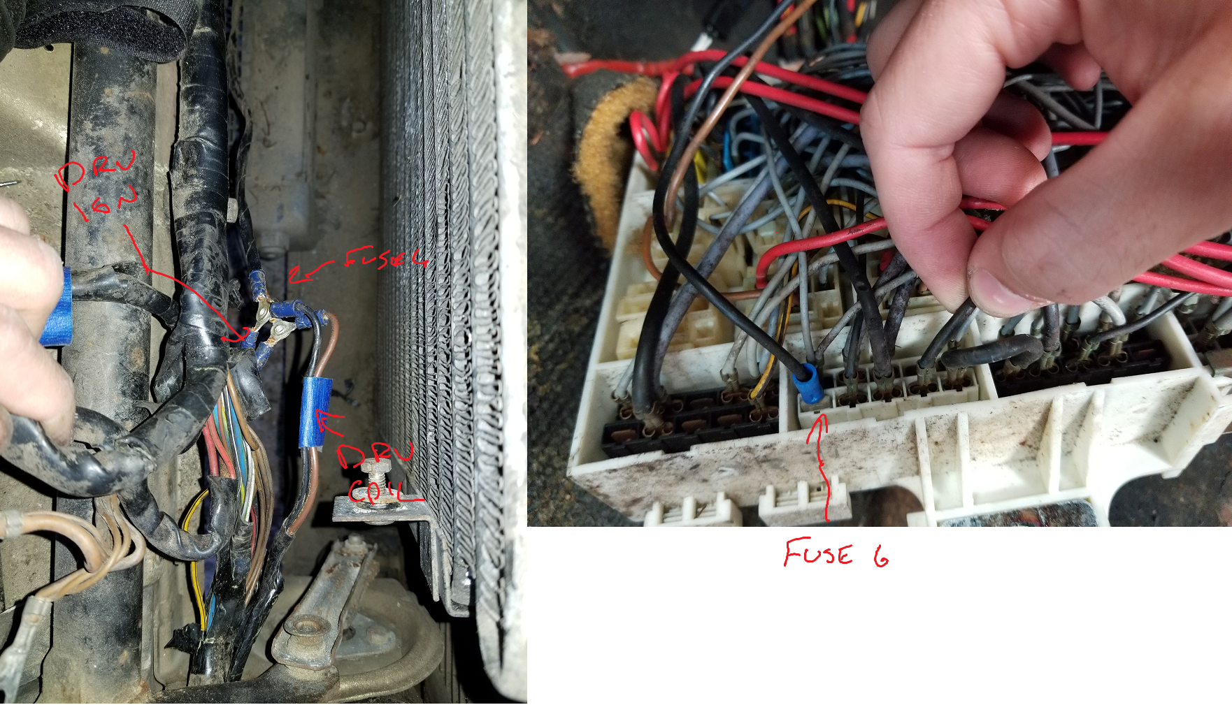
So the wire that's going from behind fuse 6 (presumably getting power (unfused!) there) runs up to the driver's side ignition trigger unit. The brown wire is spliced to the blue Q connector in the CE. Those two wires then piggy back up to the driver's side ignition coil.
Brown wire that goes up to that trigger unit.
That cut off wire in position Q12 appears to be meant to go to the driver's side ignition coil according to the diagram, so I'm thinking it's that cut off wire in the loom as noted below (and is the cause of the black insulation stuck to that brown wire).
In that case the brown wire with the black stripe next to it must be for the passenger's side ignition trigger unit (coming from the passenger's side coil).
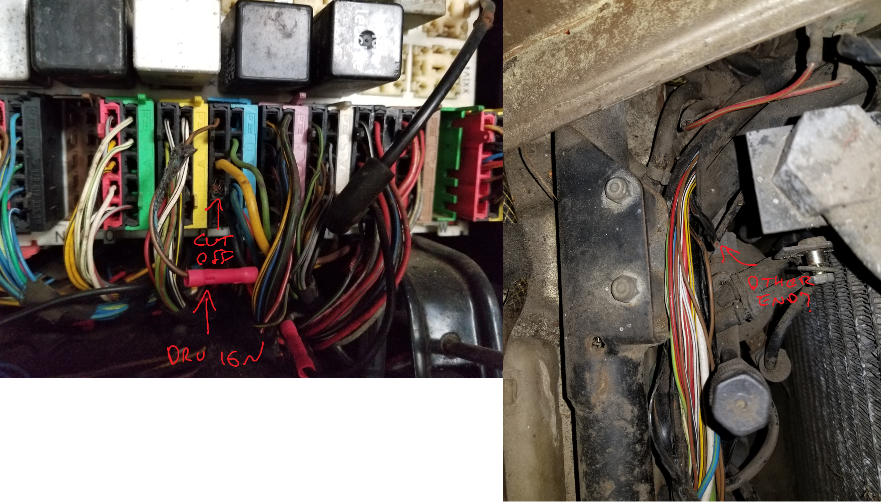
Circled and pointed out in red are the wires from Q11 and Q12 which seem to be the ignition coil wires. Highlighted in yellow is the brown/black stripe wire that has been replaced with the brown wire from Q15.
Now what I don't see on this diagram is pin Q15 which is what the brown wire is spliced to. I suspect it will probably go up to one of those brown wires going to the ignition components, but I still need to confirm that.
So if I can go through the loom and find all the places the black wire from Q12 to the driver's coil is damaged, I can probably fix the wires adjacent to it that were damaged, and replace it which should let me get rid of that wire coming from behind fuse 6.
The brown wire makes less sense. It seems like that brown wire that goes to the ignition trigger should come from the coil. It looks like there are only supposed to be 3 wires going to the coil though, the black power wire, the black wire that splits from that black wire and goes to the trigger unit, and then the brown wire that goes from the coil to the trigger unit. I don't see where there is supposed to be a second (brown) wire going to the coil or trigger from the CE.
All that weirdness aside, I think the car probably was running like this for a while. All the electrical tape that was put on the loom is just as dirty as everything else under the hood, so I don't think they taped it up and had it not work. The guy I bought the cars said it ran when parked if you want to believe that.
So do any of the service manuals people have mentioned have better wiring diagrams than this pdf? Maybe one that says what Q15 is supposed to go to?
Does anyone know of any common issues with the coil and trigger that someone might have been trying to fix?
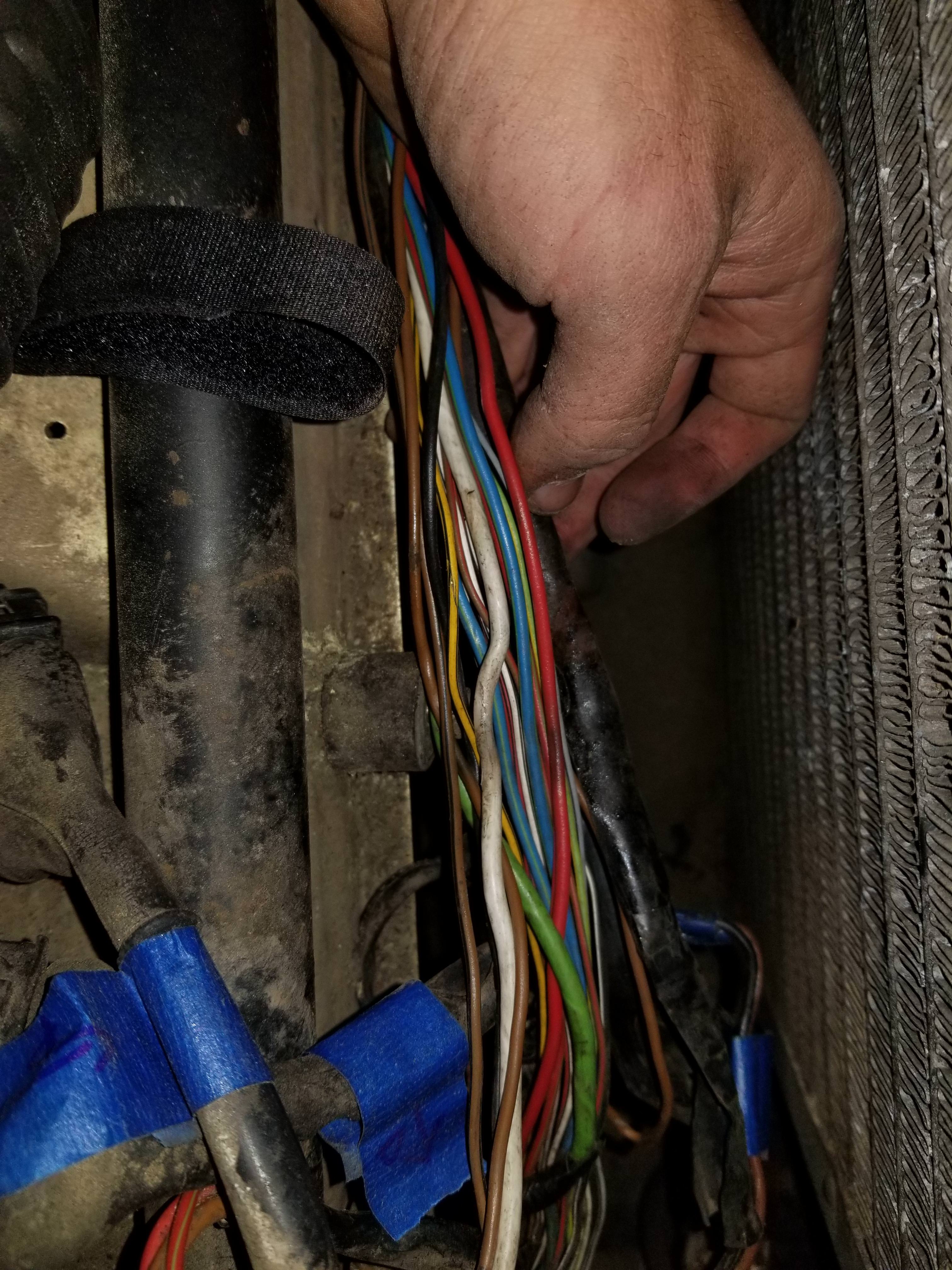
The whole loom across that front brace/support was split open and taped back up.
The connector dangling on the right there was from the fan. The one on the left that's dirty was just dangling there though.
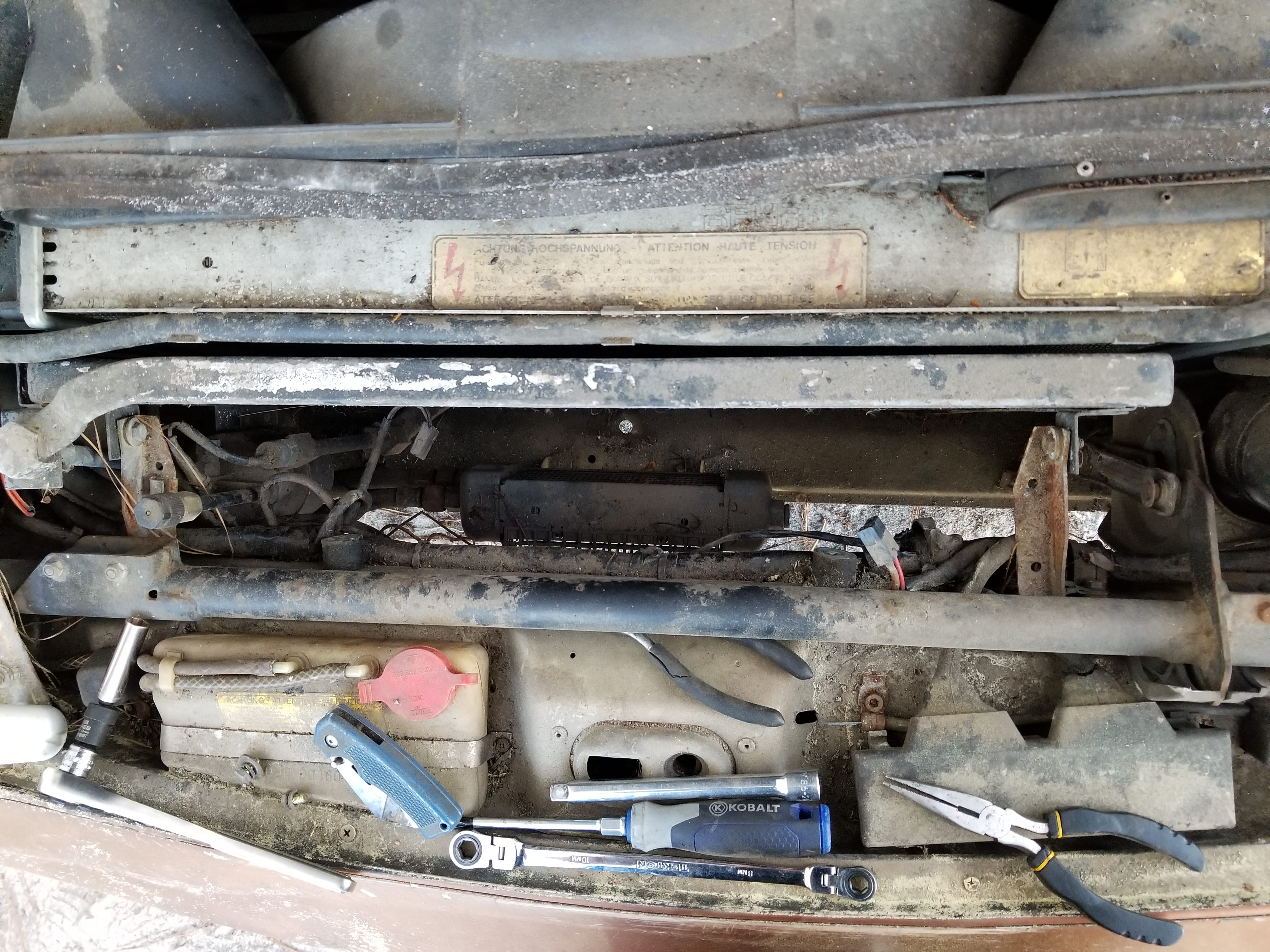
After I peeled the tape off and pulled the wires out.
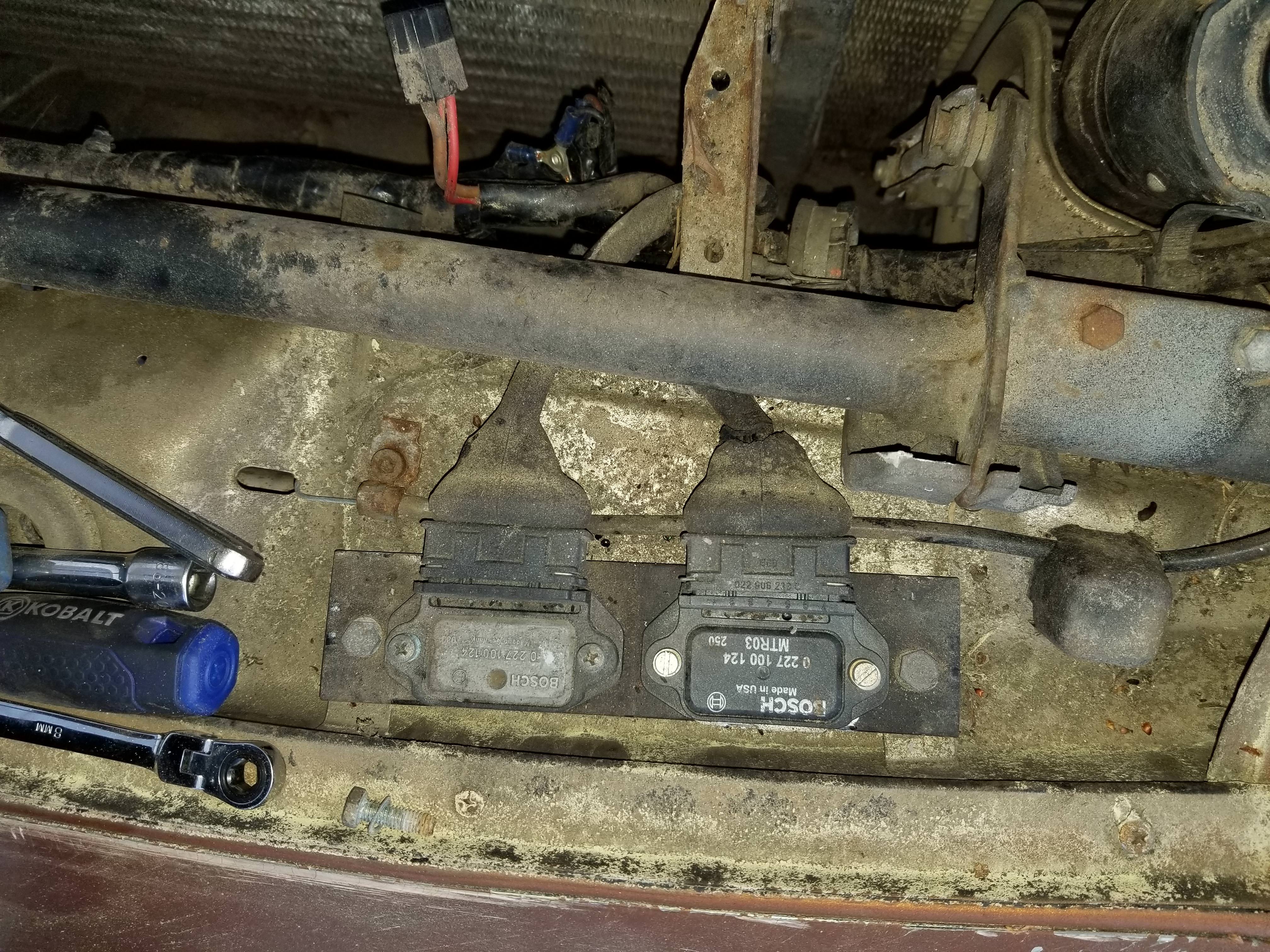
This area right before the triggers looked to have been hot at one point. Maybe from the removed black wire?
Ignition trigger on right is the one with the wires spliced to it. It also looks to have been replaced.
So the wire that's going from behind fuse 6 (presumably getting power (unfused!) there) runs up to the driver's side ignition trigger unit. The brown wire is spliced to the blue Q connector in the CE. Those two wires then piggy back up to the driver's side ignition coil.
Brown wire that goes up to that trigger unit.
That cut off wire in position Q12 appears to be meant to go to the driver's side ignition coil according to the diagram, so I'm thinking it's that cut off wire in the loom as noted below (and is the cause of the black insulation stuck to that brown wire).
In that case the brown wire with the black stripe next to it must be for the passenger's side ignition trigger unit (coming from the passenger's side coil).
Circled and pointed out in red are the wires from Q11 and Q12 which seem to be the ignition coil wires. Highlighted in yellow is the brown/black stripe wire that has been replaced with the brown wire from Q15.
Now what I don't see on this diagram is pin Q15 which is what the brown wire is spliced to. I suspect it will probably go up to one of those brown wires going to the ignition components, but I still need to confirm that.
So if I can go through the loom and find all the places the black wire from Q12 to the driver's coil is damaged, I can probably fix the wires adjacent to it that were damaged, and replace it which should let me get rid of that wire coming from behind fuse 6.
The brown wire makes less sense. It seems like that brown wire that goes to the ignition trigger should come from the coil. It looks like there are only supposed to be 3 wires going to the coil though, the black power wire, the black wire that splits from that black wire and goes to the trigger unit, and then the brown wire that goes from the coil to the trigger unit. I don't see where there is supposed to be a second (brown) wire going to the coil or trigger from the CE.
All that weirdness aside, I think the car probably was running like this for a while. All the electrical tape that was put on the loom is just as dirty as everything else under the hood, so I don't think they taped it up and had it not work. The guy I bought the cars said it ran when parked if you want to believe that.
So do any of the service manuals people have mentioned have better wiring diagrams than this pdf? Maybe one that says what Q15 is supposed to go to?
Does anyone know of any common issues with the coil and trigger that someone might have been trying to fix?
The whole loom across that front brace/support was split open and taped back up.
The connector dangling on the right there was from the fan. The one on the left that's dirty was just dangling there though.
After I peeled the tape off and pulled the wires out.
This area right before the triggers looked to have been hot at one point. Maybe from the removed black wire?
Ignition trigger on right is the one with the wires spliced to it. It also looks to have been replaced.
04-13-2018, 11:36 PM
#6
Burning Brakes
Thread Starter
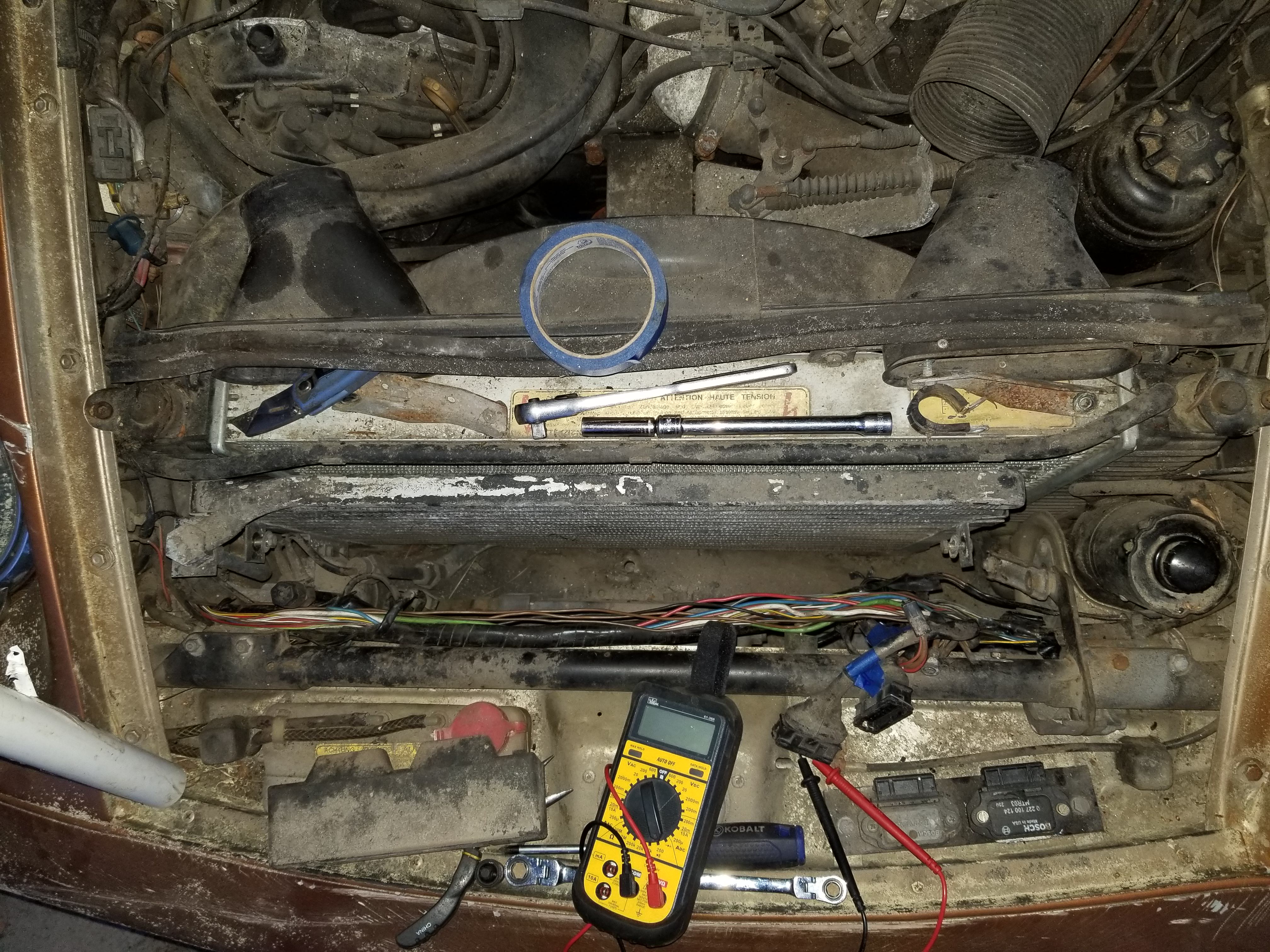
And stepping back from that ignition wiring mess, I replaced the gacked black wire from the back of the CE, which come to think of it is going to Q11 which is supposed to be for the passenger's side ignition coil, with a new piece of wire.
So the way that black wire is running to the driver's side trigger unit is effectively the same as the way the passenger's side was wired, so hopefully that means it is fused somehow.
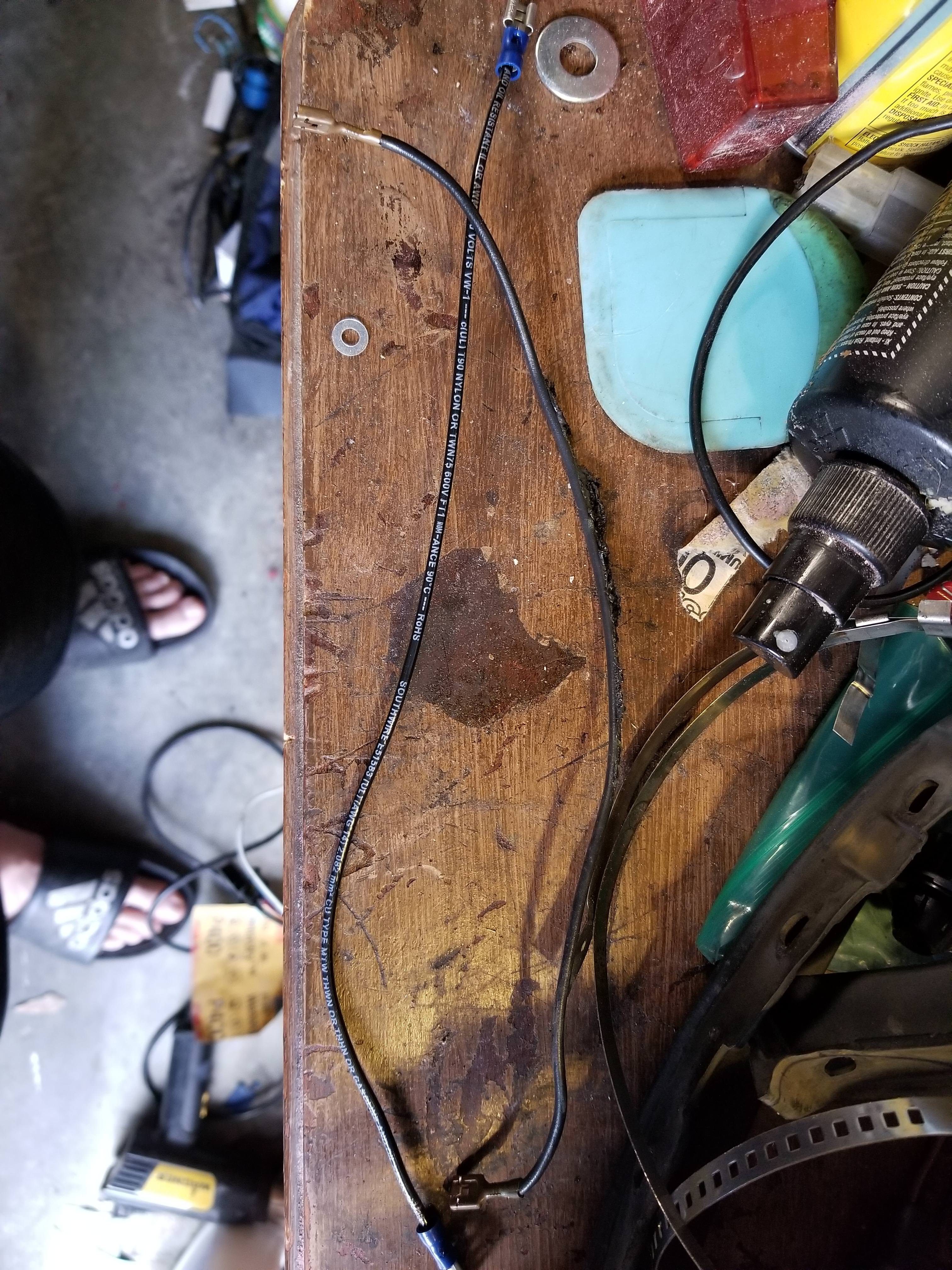
This wire went from W22 to L25. It was also gacked and is now replaced. Not sure what that wire is for.
New wires.
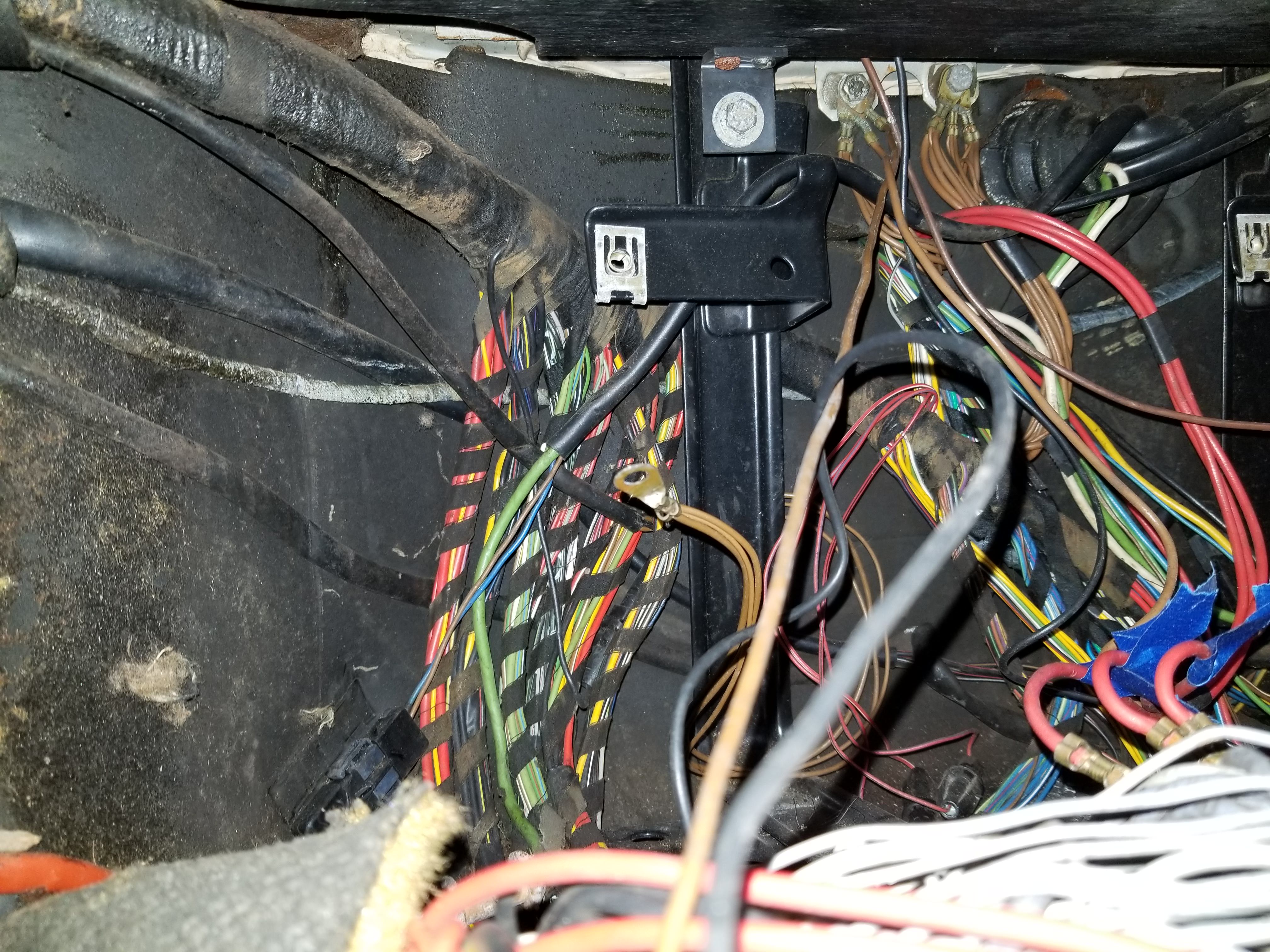
And I found this bunch of grounds that wasn't connected. Looks like the wires go into the center console, so I suspect this might be why the power windows and radio weren't working.
So the way that black wire is running to the driver's side trigger unit is effectively the same as the way the passenger's side was wired, so hopefully that means it is fused somehow.
This wire went from W22 to L25. It was also gacked and is now replaced. Not sure what that wire is for.
New wires.
And I found this bunch of grounds that wasn't connected. Looks like the wires go into the center console, so I suspect this might be why the power windows and radio weren't working.
04-14-2018, 01:48 AM
#7
Burning Brakes
Thread Starter
I think I finally figured out how the read the CE diagram. Pin Q15 (the where the brown wire is spliced) looks like it points to grid F22, which shows Q15 as being wired to the front right brake pad sensor. It also shows that Q15 is connected to S14 which is for the rear right brake pad sensor. I'm guessing they're all daisy chained together to turn the light on or something. Anyway, I have no idea why the ignition coil is wired to that, but I'm going to go ahead and assume it shouldn't be.
Trending Topics
04-14-2018, 09:18 AM
#8
Rennlist Member
Join Date: Feb 2016
Location: Stafford, VA
Posts: 54
Likes: 0
Received 0 Likes
on
0 Posts
To answer your question; I have not seen or heard of any other wiring diagrams other than the PDF ones you have. They take a while to get used to reading (there are SOOOO many wires) but I have found them very accurate in how things should be wired. Looks like the PO had some electrical gremlins and started cutting and splicing wires to make things work without knowing what was actually going on.
04-14-2018, 12:25 PM
#9
Burning Brakes
Thread Starter
Got back to work on that wiring this morning. It seems like the damage to the black wire that's meant to go to the ignition coil was more or less isolated by the previous owner (most of it has just been removed). That black wire going to it now appears to be of similar gauge. so I've replaced the riveted together ring connectors with a set of spade connectors. It looks the one wire that ran back from the ignition coil to the trigger unit was just connected to the black wire going to the coil anyway, so I've just left it teeing off there as the previous owner did.
According to the wiring diagram, the brown/black stripe wire on the trigger unit is supposed to go to other side of the coil, and that's it. I suspect whoever fixed this before saw the damaged brown/black strip wire for the brake sensor on the same CE connector (Q) and mistook it for being that trigger wire. So I have disconnected the brown wire going from the CE to the ignition coil altogether. I did not yet reconnect the brake wire in case anything is funny with it still.
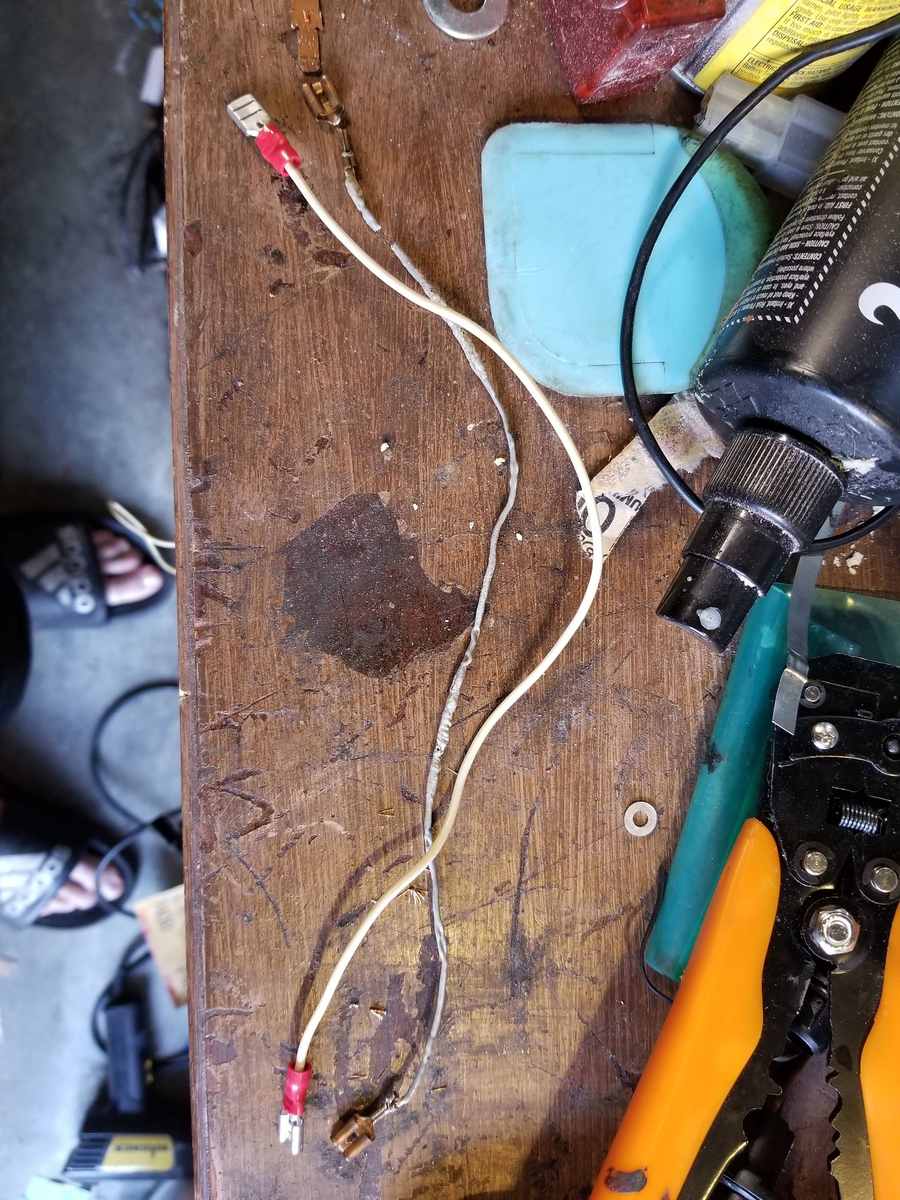
New spade terminals. Will be heatshrinked.
I've also taped up the damaged insulation on the green shielded wire.
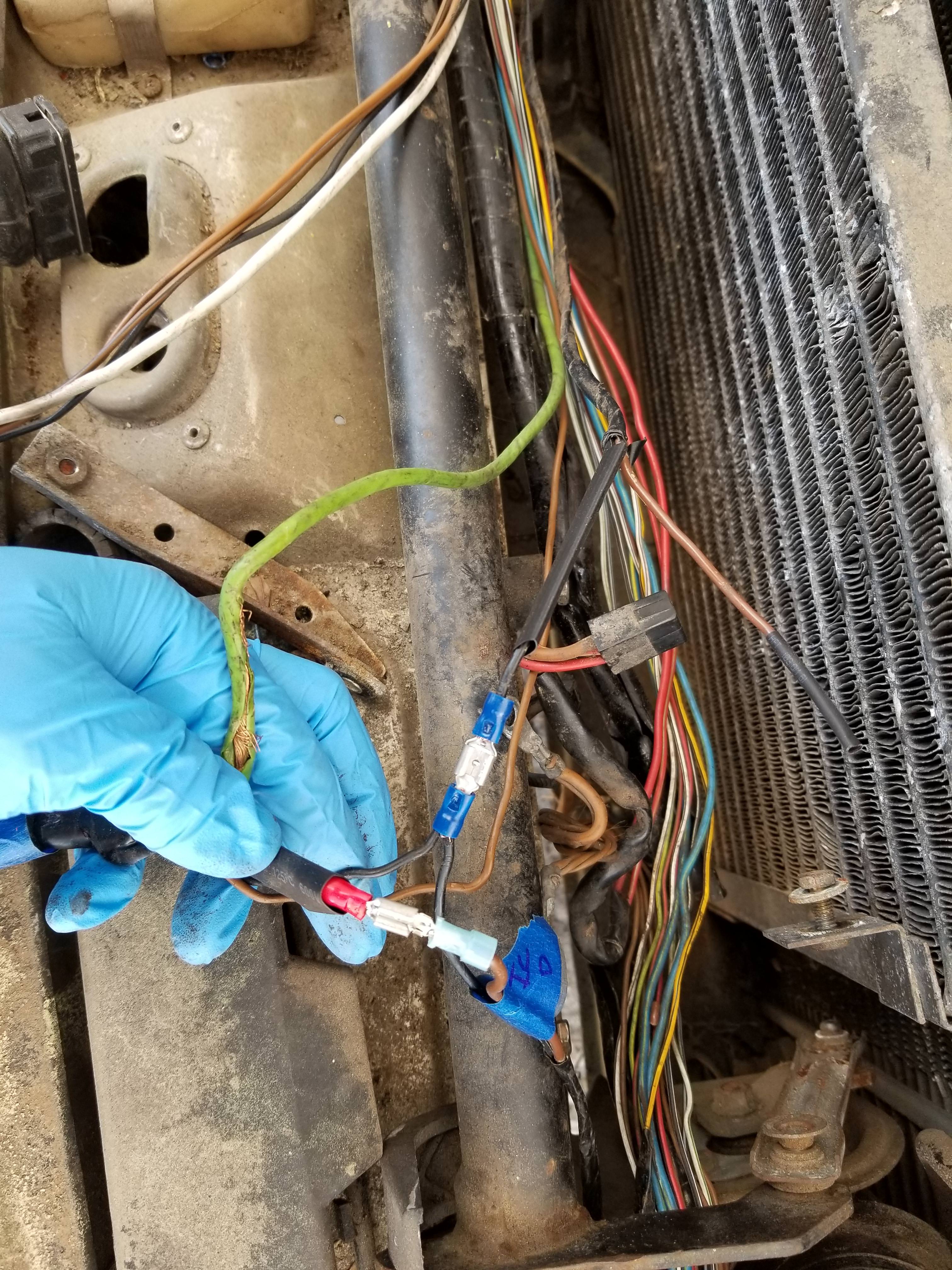
And for now I've just disconnected the brown wire from the CE. Since Q12 on the CE just went to the backside of fuse 7 anyway, I've just left the black wire go straight there for now rather than reconnecting it to Q12. I'll fix that eventually though.
So really all I changed is removing the brown wire that was going from Q15 (brake sensor) to the coil and trigger unit. If this seems wrong or I'm missing something here, please tell me. I'd much rather fix it that damage something else. I do plan on fixing this better down the road, but it seems like that isn't happening without ripping the engine and dash out at the same time.
I'm also in the process of tracing another spliced wire to the back of the car. I was hoping to get to work on the timing belt this weekend, but I'm running short on time today before I have to go somewhere, and tomorrow it's supposed to be raining.
According to the wiring diagram, the brown/black stripe wire on the trigger unit is supposed to go to other side of the coil, and that's it. I suspect whoever fixed this before saw the damaged brown/black strip wire for the brake sensor on the same CE connector (Q) and mistook it for being that trigger wire. So I have disconnected the brown wire going from the CE to the ignition coil altogether. I did not yet reconnect the brake wire in case anything is funny with it still.
New spade terminals. Will be heatshrinked.
I've also taped up the damaged insulation on the green shielded wire.
And for now I've just disconnected the brown wire from the CE. Since Q12 on the CE just went to the backside of fuse 7 anyway, I've just left the black wire go straight there for now rather than reconnecting it to Q12. I'll fix that eventually though.
So really all I changed is removing the brown wire that was going from Q15 (brake sensor) to the coil and trigger unit. If this seems wrong or I'm missing something here, please tell me. I'd much rather fix it that damage something else. I do plan on fixing this better down the road, but it seems like that isn't happening without ripping the engine and dash out at the same time.
I'm also in the process of tracing another spliced wire to the back of the car. I was hoping to get to work on the timing belt this weekend, but I'm running short on time today before I have to go somewhere, and tomorrow it's supposed to be raining.
04-14-2018, 01:16 PM
#10
Rennlist Member
OCD, I like the way you operate, brother.
Straight into the electrical. Didn't talk about fancy wheels, pretty seats or stereo. Good approach. You will win.
There is a CD set, not from internet but from 928s Rus that has some supplementary electrical information along with full wsm, and other tech info. Must have, really.
Straight into the electrical. Didn't talk about fancy wheels, pretty seats or stereo. Good approach. You will win.
There is a CD set, not from internet but from 928s Rus that has some supplementary electrical information along with full wsm, and other tech info. Must have, really.
Last edited by Landseer; 04-14-2018 at 02:07 PM.
04-14-2018, 02:59 PM
#11
Burning Brakes
Thread Starter
Don't want anything burning up when I get ready to try and make it run.
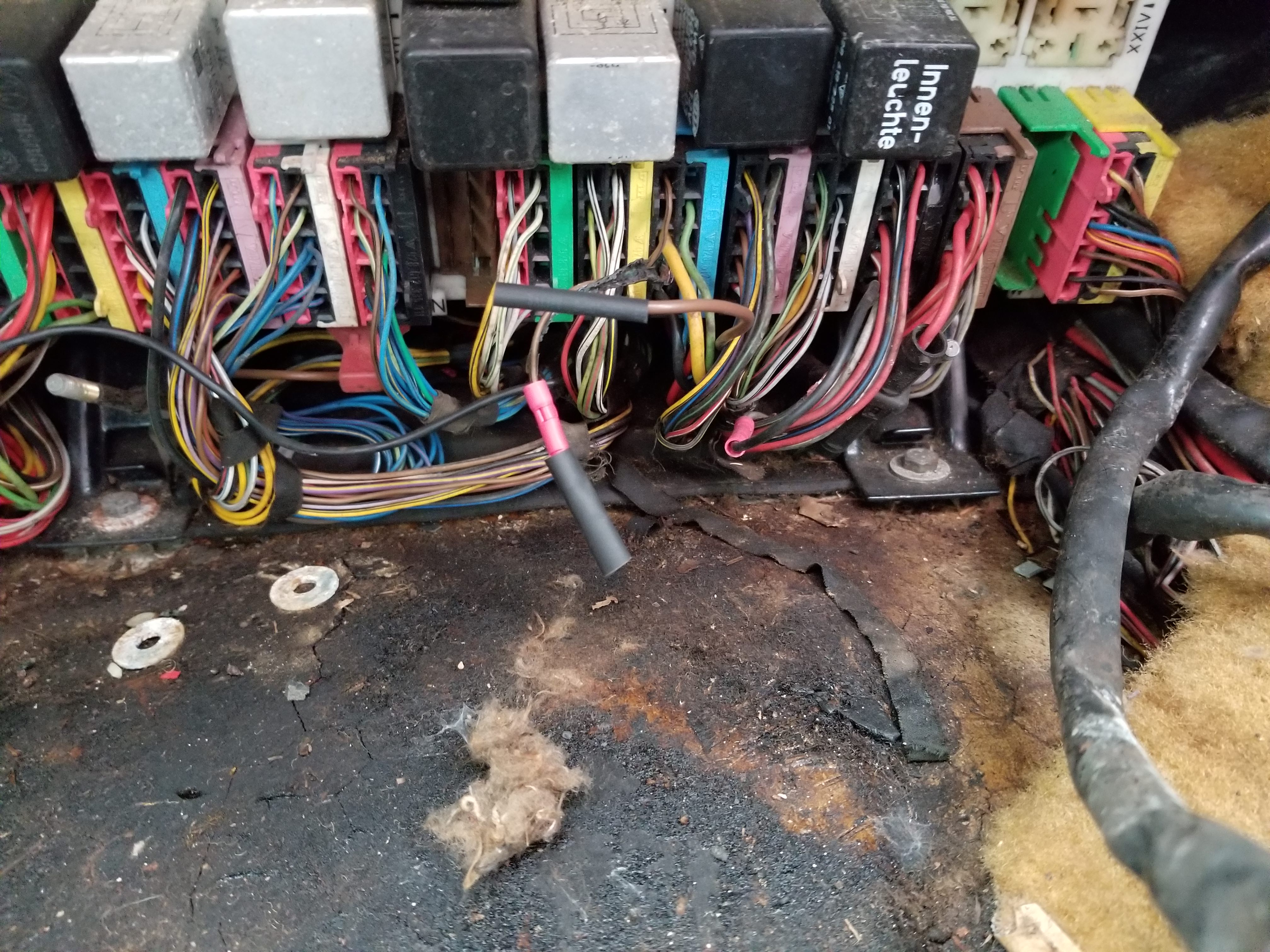
Traced the spliced wire from the T CE connector to be interior lighting. Looks like the original red wire melted and damaged some other wires around it. Seems like they're just taped up, so I probably need to replace a couple sections of them.
And I suspect the front dome light was the cause of the short or whatever melted that red wire. It's got 3 wires going to it now. 1 which is spliced to the T connector, and a piece of lamp cord. The plastic just disintegrated when I pulled it out of the headliner and some of the old wires on it look damaged.
04-14-2018, 06:02 PM
#15
Burning Brakes
Thread Starter
Well at least that one is already broken. Maybe it's time to get creative with the 3d printer then.