When you click on links to various merchants on this site and make a purchase, this can result in this site earning a commission. Affiliate programs and affiliations include, but are not limited to, the eBay Partner Network.
Very interesting, Pete. Good analysis and problem finding. I agree with you, that the larger filter area is the way to go. What you have will work better and last longer than the Spectre filter, and I would leave it just as you have it. It's a very nice design.
Thanks,
Dave
I've completed v3 of the cold air intake on my Spyder and was able to shoehorn it in as originally conceptualized. The airbox itself is a Carbonio TS model that's construction of Carbon Fiber - it's actually very well made and quite pretty.
Here are pics of the process and finished product. I'll do another update after the first drive, but I think it turned out quite well and conceptually should prevent the supercharger from sucking in hot air that has come through the radiator, providing for more dense air and more power.
Hi Pete,
Looking good!! One question, do you think you can get a bellmouth on the end of the air inlet entrance? I think that will increase/smoothen the airflow going into the "entrance".
Just a thought, Happy Sunday,
Dave
__________________
David Roberts
2010 Jaguar XKR Coupe - 510HP Stock - Liquid Silver Metallic
928 Owners Club Co-Founder
Rennlist 928 Forum Main Sponsor www.928gt.com
I wish I could include something like that in the base kit, but we advertise the kit requires no mods to your 928, so I have to stop short of telling the owner to drill 4" hole sin their fender wall
I like this cold air install very much, and am pleased to see it using the right-sized air filter.
Drove the car with the new intake last night and it feels essentially the same as the v2, and the boost gauge is showing the same thing - usually up to 1.5 lines and if I held it full out past 5,000 RPM might move up to 2 lines, which I'm assuming is 0.2 bar or 2 lbs - still too low. Today I thought it about it further and decided that there's no way both the v2 and v3 intake setups are doing exactly the same thing so I had the thought that maybe the vacuum line that goes to the gauge somehow got crimped or something so tonight I took loose the front of the carpeted Plexiglas side panels I made (more on that in a minute), and lo and behold. wiggling the hard boost line that comes in and connects to the short section of silicone boost hose that then connects to the gauge, it completely came apart so it was either just barely connected or disconnected, but still maybe touching enough to register some boost and some vacuum, but I'm sure not providing accurate readings at all. I reinserted the hard line into the soft line and this time clamped the joint with the smallest clamp I had in the drawer, which seems to provide at least a little pressure. I'll drive it again tomorrow and see what kind of boost I'm getting, but I bet it's back to how I remember it, which also explains why the car didn't really feel any different from the v1 intake to the v2 intake to the v3 intake even though the boost gauge was showing a difference from v1 to v2/v3. I'll stick with the v3 intake setup as
I think the execution of the v3 is the best of the 3 with the greatest opportunity to suck in the most cool air and not experience any heat soak from behind the radiator as the carbon fiber airbox should be a worse conductor of any ambient heat that exists in that area from the radiator expelling heat than the aluminum Spectre housing would.
I also had to trim the length of the Spectre housing at the center joint in order to fit it into that area, so the point of the filter cone was probably a bit too close to the inlet aperture for optimal flow,
I have a lot more filter media in the larger cylindrical filter in the Carbonio airbox than I had in the smaller conical Spectre filter so longer service intervals and probably better filtering,
Carl also brought up a good point about air velocity through the filter and filtering efficacy, so I think this setup better protects the motor from particle debris
and, it's currently installed so I can leave it as is and move on to other projects.
Unfortunately, with the loose boost gauge hose connection, it means we didn't get any data about the v2 intake and whether that setup cost any boost due to air flow or capacity. I'll report back after the drive.
I agree with everything above. Another way for me to look at it is that my intake design was probably working fine, since it was your gauge that suggested a restriction. I do really like your solution though .
Thanks,
Dave
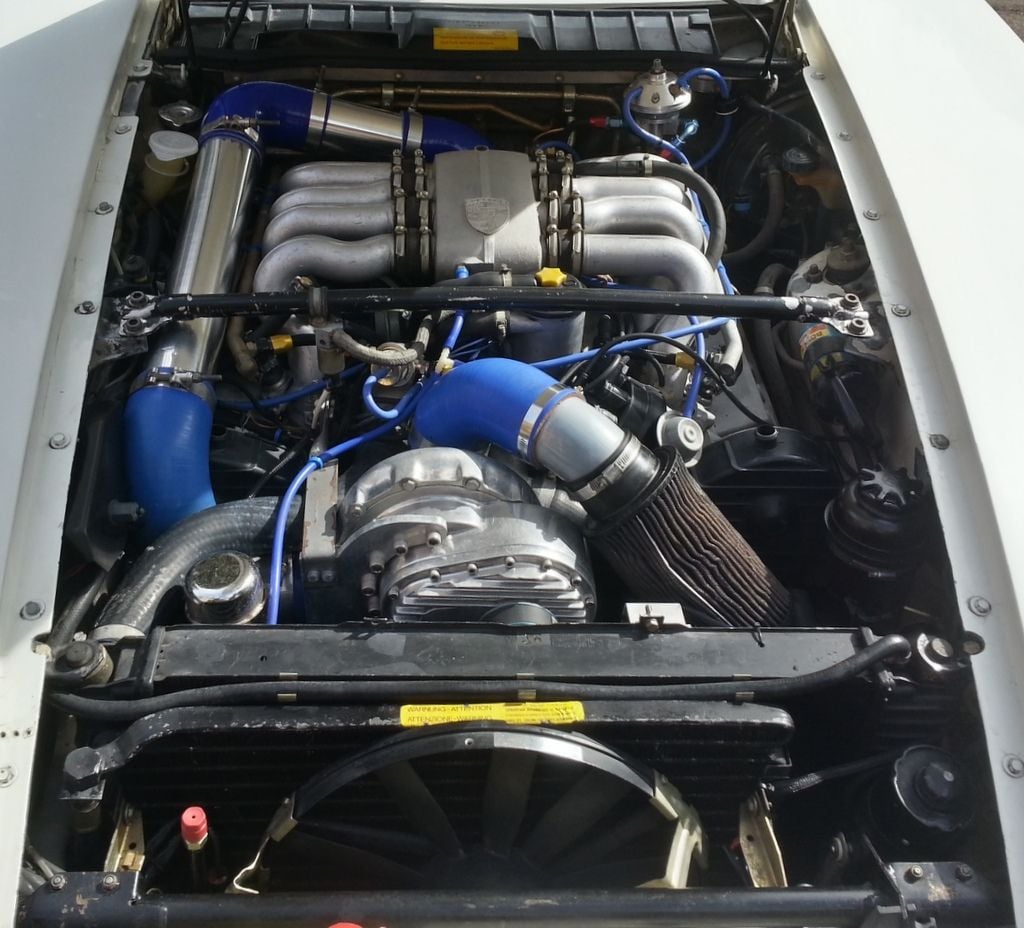
I love the look of the stock engine, so this blue silicone nightmare was killing me, plus the loss of all stock airflow control was functionally bothersome.
Mocked up the solution below, using a modified stock upper shroud and some simple ducting to get both cold air ports over to the filter.
Not seen is the simple heat shield on the bottom half of the air filter so it isn't inundated with the hot radiator air.
Pleased with it aesthetically, and can happily convince myself that it's functionally well above its previous condition.
Simple - nice. Might work even better if your were to heat shield shroud that filter except at the area where the cold air inlet tubes are positioned.
A couple other things - on the MFI cars I've been told not to install a permanent fuel pressure gauge on that fuel rail as they are a more common failure point and will result in an engine fire. Different story on the later CIS cars for some reason.
What is the silver pointy component with the blue AN fillings going to it - is it some form of catch can, crankcase vent/breather, or something else?
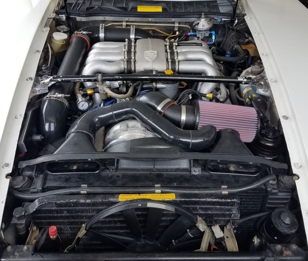
Thanks, Carl. I have to say, if I hadn't been able to get it looking better I may have had to put it back to stock! Figured if I could get all the aftermarket stuff blacked out, I'd be close to the stock look of the spider dominating. Fiddled with the air filter, and when it suddenly popped into that horizontal position the rest of the basic plan came together.
Pete, can't see it, but note there is a clamp on heat shield around the bottom of the air filter. Radiator fans are right there blowing on it otherwise. With car in motion, there ought to be a decent cloud of cooler air up around the filter.
I've heard that about the fuel pressure gages, too. It was there when I got it, and still utilizing it while getting the tuning dialed in better, so it will stay for now.
Silver thing with AN fittings is a fuel pressure regulator ("Fuel Management Unit"). Bumps up fuel pressure under boost.
Silver thing with AN fittings is a fuel pressure regulator ("Fuel Management Unit"). Bumps up fuel pressure under boost.
Interesting. Do you have a wideband AFM gauge that shows you were leaning out under boost? Mine stays between 12.5-14 pretty much all the time so always on the richer (safer) side even under full boost or maybe I have something similar and it's just in a different location.
Hi Pete.
I think the fuel pressure regulator that Mike is referring to is for L-jet cars only. I think your is CIS.
Great work by both of you.
Thanks,
Dave
Hi Pete.
I think the fuel pressure regulator that Mike is referring to is for L-jet cars only. I think your is CIS.
Great work by both of you.
Thanks,
Dave
Dave,
Could be and that would explain it - mine is a '79 K-jet car.
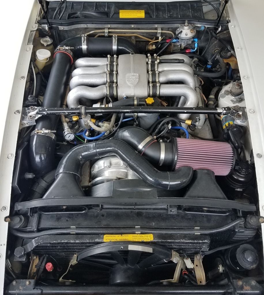
I also think as part of restoring function to my supercharger Heat exchanger cooling pump and fan, that I may have also found where some of my boost may have been going, but I'm not sure I fully understand the air flow. Seems to me that air enters the intake goes into then out of the supercharger, runs along the long tube down the side of the engine bay, enters the intercooler, then gets routed down under the spider intake, comes back up through the throttle body and into the spider body where it then gets routed into the engine through the spider legs. If that's about right, the joint where the intercooler connects under the spider body looks like it may have not been seated well with a small gap at the front.
Look through the spider legs - see how at the front, the top metal piece isn't seated into the groove in the bottom piece and there appears to be some staining in this area on the top piece where a boosted air leak may have been occuring.
I took that junction apart and cleaned everything, then applied some weatherstip tape along the edge of the top piece, reseated it, and adjusted the bolt that goes through the top of the Spider intake to push down onto the top piece with more force and it's locked in there nice and tight now.
So once I get things back together, we'll see what kind of boost we get and if that was a contributing factor.
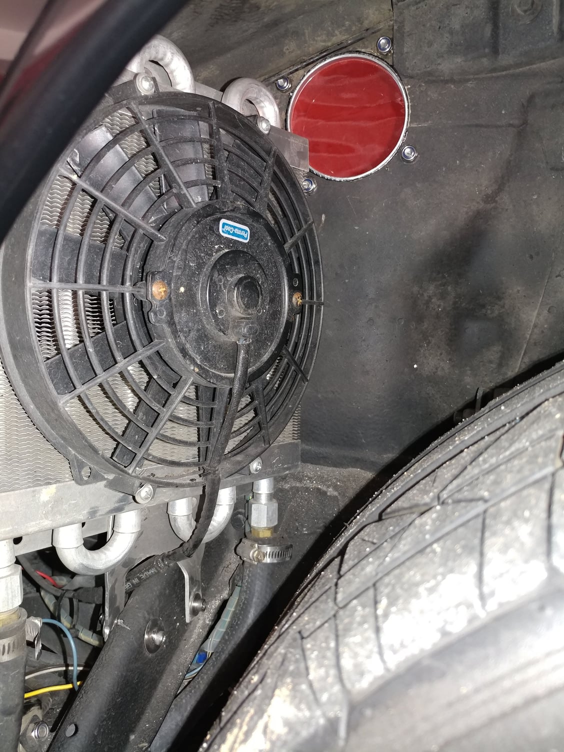
The reason I started into this this week is because I didn't believe the pump that feeds windshield washer fluid to my intercooler heat exchanger was working. First off, I didn't realize that the pump used windshield washer fluid from that reservoir as the cooling medium. I haven't had more than 3" of fluid in that reservoir ever, because one of the POs of this car put a ground screw through the metal wall from the inside passenger area, right into the coolant reservoir. When I redid a bunch of the interior wiring, I removed this unnecessary screw and washer fluid started running into the car. Not wanting to risk that happening after it was all done, I just let it drain out to below the screw hole and never filled it up again (4 years this way).
So, step one was to fix that problem. I made the hole in the sheetmetal a little bigger so I could get good access to the screw hole in the water bottle, mixed up some JB Weld. forced it into the screw hole, then sealed up the enlarged sheet metal hole too - reservoir should be water tight now so I can use my windshield squirters and have a large fluid capacity for the heat exchanger fluid. Patch is the grey circle in the middle of the photo.
Then I started looking into the pump itself. Put 12v do it directly - nothing. That's not good news. Removed the pump so I could work on it in a better area. Tried it again out of the car - nothing. Apart it comes to reveal this and an impeller that I can't spin by hand.
I eventually scraped away enough of the crust to turn the impeller by hand so the motor wasn't seized - good news as this is a high end pump that costs about $400. Soaked the two pieces in CLR overnight, cleaned up the gasket surfaces, cut a new gasket from some silicone sheet material I had, and reassembled.
Back in business...
There are so many wires in that section of the car for the Xenon headlights, air horns, HE pump, HE fan wiring, etc that I'm going to redo how all that is done as multiple things were on shared circuits, etc. I'm going to mount a waterproof marine fuse box there as a secondary one so each wire can be on it's own fused circuit.
One side will get a Constant 12V feed from a wire I run to the jump post (push/pull fan controller, Xenon lights controller, etc) and another side of the fuse box will get a switched 12v feed. I'll use an SPDT relay, take one lead from the constant side of the fuse box to supply pin 30, take a trigger lead from a splice on a switched wire at the 14 pin connector to pick the relay, then use the other leg of the relay to supply the switched side of the fuse box and all the switched circuits will come off of that. The relay is an 30A so won't have any trouble supplying power to that side of the fuse box for the few switched circuits (HE fan, HE pump, etc).
The pump is reinstalled, all the wires are labelled ...
...just waiting for the waterproof fuse box to arrive tomorrow so I can put it all back together and I'll have my Stage 2 setup back in action, hopefully with more boost.
Could be and that would explain it - mine is a '79 K-jet car.
I also think as part of restoring function to my supercharger Heat exchanger cooling pump and fan, that I may have also found where some of my boost may have been going, but I'm not sure I fully understand the air flow. Seems to me that air enters the intake goes into then out of the supercharger, runs along the long tube down the side of the engine bay, enters the intercooler, then gets routed down under the spider intake, comes back up through the throttle body and into the spider body where it then gets routed into the engine through the spider legs. If that's about right, the joint where the intercooler connects under the spider body looks like it may have not been seated well with a small gap at the front.
It is also possible on K-Jet cars to blow the throttle body down off of the plenum with boost. That would cause a boost leak at the connecting hose #19 in this picture. It is only attached to the plenum with hose clamp #20. This isn't common, but I have done it. Usually, if the plenum cannot move up and the throttle body cannot move down, you are all set. But the intake manifold was painted after I delivered you the car and I am not certain how it was put back together and whether clamp #20 was tightened. Get a mirror under there and check, and see if there is a clamp on both the top and the bottom of hose #19.
I'm not saying that's your boost leak, but it could be. I'd forgotten that you had the intake on and off again after the install until I saw your pretty red runners again today.
Good thought Carl. I checked that one when I was going through all of the plumbing last night. The only thing I say that looked like it could result in air escaping was the large black metal piece that's part of your kit after the silicone hose from the intercooler, and you're correct - I had all of that apart a couple years ago when I painted the spider plenum and installed the red powdercoated Euro spider legs, so it's possible that it has been like that since then and I just didn't realize my boost was down until I did the cold air intake and started paying more attention to it after that based on the comments about restricted air flow in this thread.
I think what's in these pics is what you're talking about and everything looks tight and secure there.
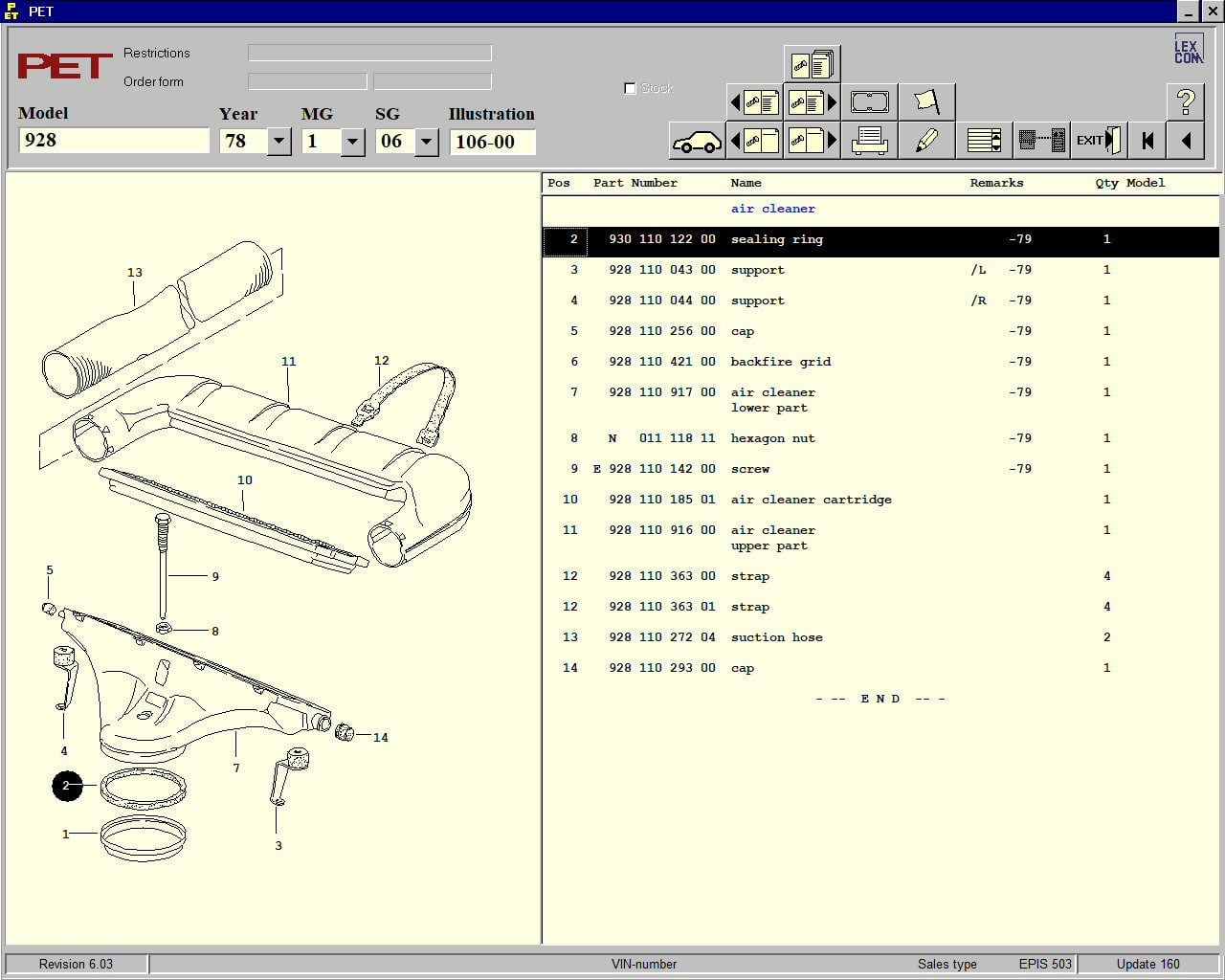
Back in the day, there was a foam "sealing ring" that fit over the intake shoe and sealed between it and the air filter housing. Item #2 in the PET below. They always come off the cars looking like an old paper gasket, compressed and brittle.
If you want to seal that space between our CIS adapter and the shoe, what I have done is to make a O-ring seal by using a piece of small-gauge silicone vacuum hose like that which we sell. Cut it with a razor blade to length so it wraps around the outside of the shoe, and splice it together with the shaft of a golf tee or similar. When finished, you will see the silicone hose makes a nice seal between the CIS adapter and the shoe.
It is not required to seal that small gap, however, unless you want absolutely every drop of boost you can get. Its a small out-gas area, and it is before the air is metered, so it does not effect the tune. As air is escaping there, no dirty air can get sucked in to the motor - air is being blown out. The bolt in the top center of the plenum (#9 below) pushes down on the intake adapter so it cannot pop-off (as long as it is tightened down enough). What we are discussing here is a very small amount of air that can spill out of this connection before the shoe.

 06-17-2018, 08:36 AM