When you click on links to various merchants on this site and make a purchase, this can result in this site earning a commission. Affiliate programs and affiliations include, but are not limited to, the eBay Partner Network.
Seth - In just a few words you pretty much created a good image of what is involved. Thanks! EDIT: OMG...just skimmed your thread several posts before and after #17. Nice work and fantastic documentation!
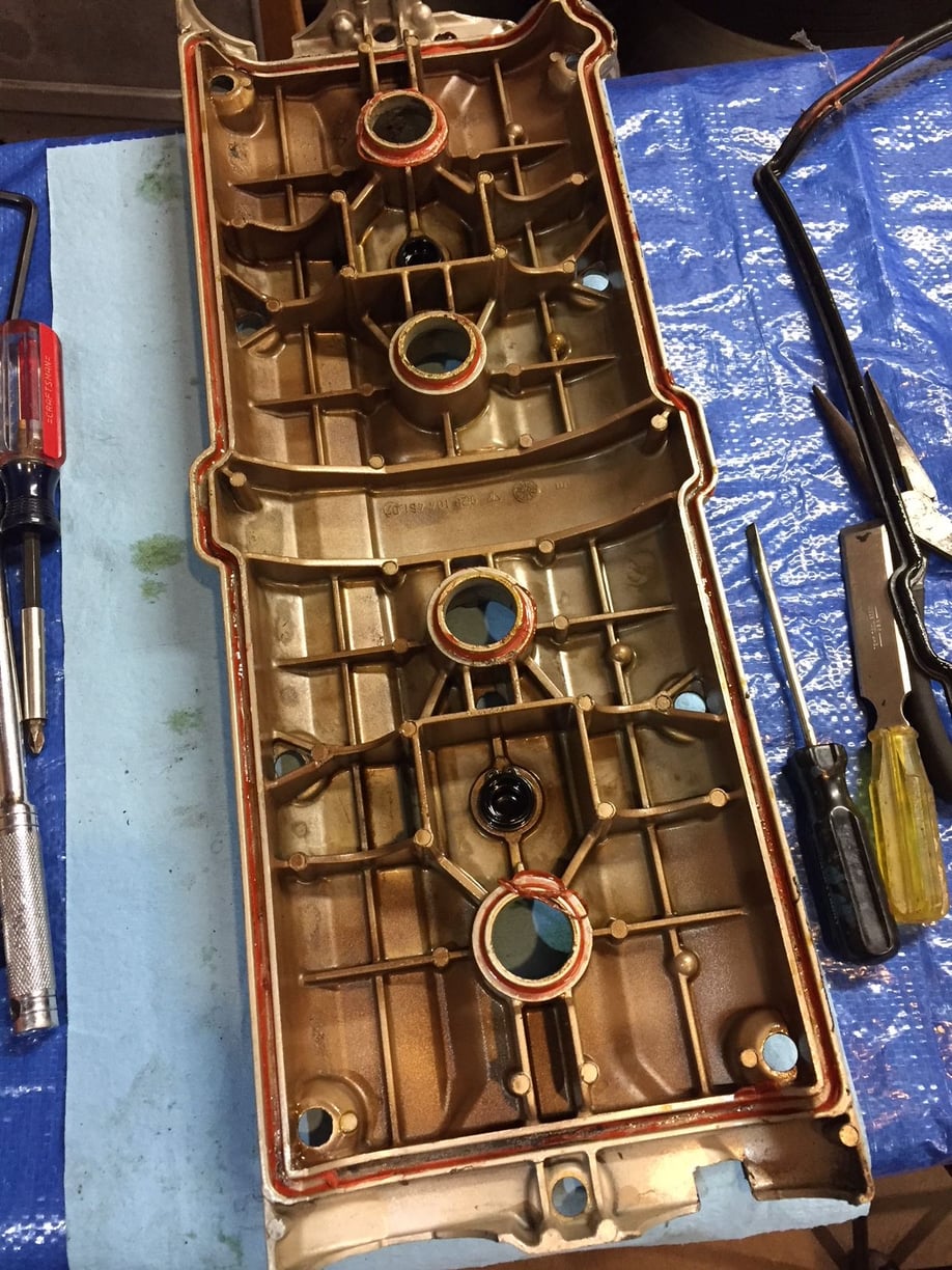
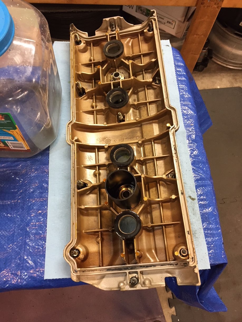
The driver side has red silicone sealant. The passenger side does not (and looks original). So someone either tried to stop some leaking, or something was serviced...but the leaking seems more probable. Any ideas on what else could explain this?
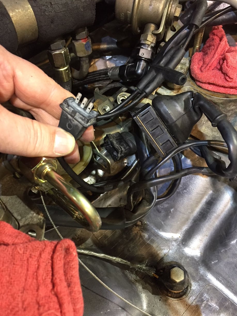
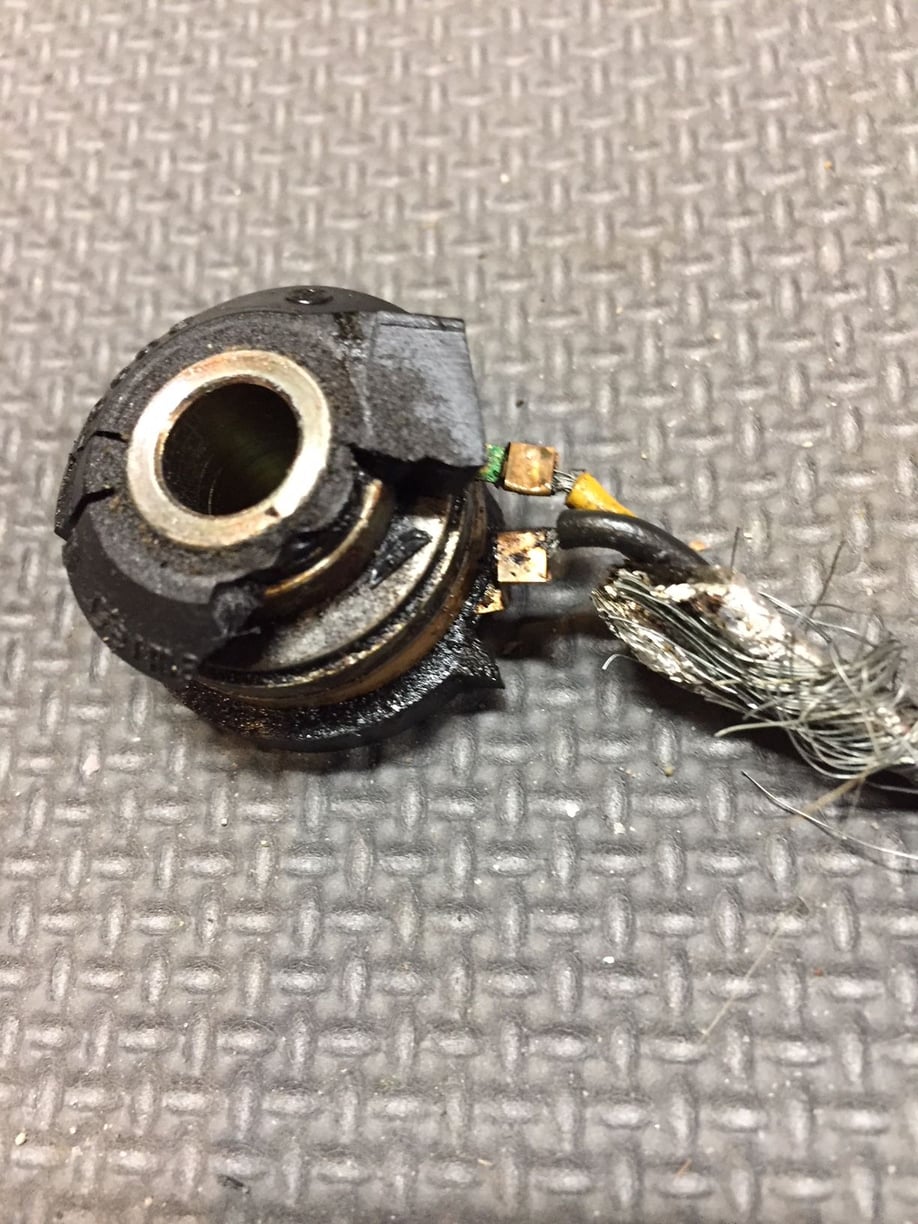
The CPS connector failed inside harness-side connector
The CPS did not look bad. Nothing like the knock sensors. However, the plastic connector broke off inside the harness connector. I hope it's as easy to pick out as the knock sensors (the extreme brittleness of the knock sensors made for easy picking...this might be tougher). Based on my experience I'd suggest replacing the CPS no matter how good it looks (assuming yours didn't fail when separating the connectors).
The driver side has red silicone sealant. The passenger side does not (and looks original). So someone either tried to stop some leaking, or something was serviced...but the leaking seems more probable. Any ideas on what else could explain this?
Someone took off the d-side cover and rather than replacing the gasket they used permatex red. And/or they used permatex red as an assembly aid. A common issue with CC R&R is that during final placement one of the plug gaskets will dislodge or one of the corners of the CC gasket will dislodge. The result is - obviously - a significant oil leak. Screwing up the gaskets is easier on the passenger side because of the plastic 'oil separator' that gets in the way.
For the gasket corners, I use a loop of brass safety wire (which is thin and soft so it's easy to cut and doesn't scratch) as a 'twist-tie' through each corner bolt hole. Once the non-corner cover bolts have been started, I snip the wire and withdraw it from each corner. For the plug gaskets, use your eyes, a mirror and a bent pick to make sure they are 'there.'
If you are powder coating the covers and the inside perimeter gasket channel or the bottom of the plug holes gets coated, use permatex gray on those surfaces. The PC is 'slick' and oil can get through. The permatex will last longer than the rubber gasket anyway. And lets face it: the factory had problems keeping the CCs sealed at the bottom hence the use of the tiny aluminum spacer washers on the bottom bolts.
Dave,
Thanks! Great tips. Reminds me of tricks for installing the OPG.
Stan,
Thanks for following along. I'm using a lot of DC111 on this job. Great stuff. And I cleaned the two grounds in the back...using Deoxit 100. Also, you and Sean replaced the fuel lines on my car as a Frenzy tech session. I am amazed that either you or Sean noted the CPS was nearing its end. It looked fine to me, but sure enough it is brittle and the connector failed on the sensor side.
Amazing how much Roger and his elves can put into a box. This is everything for the intake refresh AND upper and lower radiator hoses, and a few other additional pieces to replace while everything is accessible.
When I bought the rear wheel liners, couldn't believe that it was in a small box like that when I got them.
They're quite soft but even then...
They were perfectly packed inside a small box.
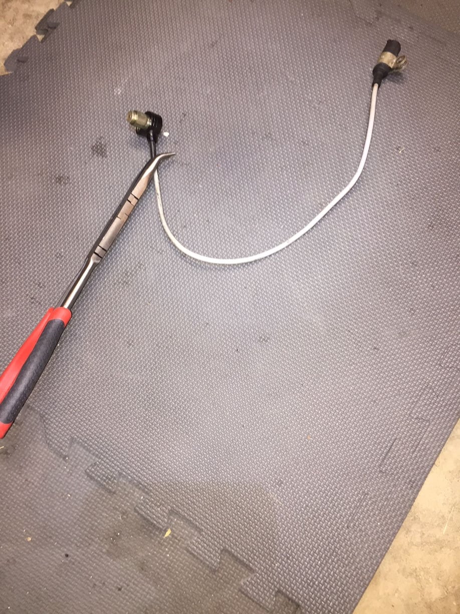
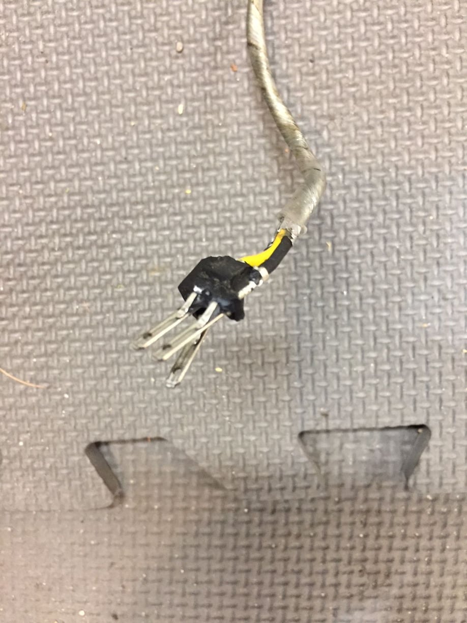
This evening I decided to do a little cleaning and pick out the remnants of the male CPS connector (sensor side) from the female CPS connector (harness side). To do so meant bending and flexing the boot of the connector 180 degrees from it's "baked-in" position of the last 30 years. I felt the boot fail and rip immediately...then saw that the insulation on the wires within had split as well. No way I could have avoided this with the engine in the car.
So now I'm thinking I should replace the connector. I don't know how much of a challenge this could be. I could return the harness to its 30-year-baked position, which would close the wounds in the stiff wire insulation, apply several coats of liquid electrical tape to flow insulation around and between the wires, then wrap and reconstruct the boot out of self-vulcanizing tape....and cross my fingers. I hope those who have dealt with this will describe what worked for them.
Note the upper wire with split black insulation has exposed silver strands. Then the middle white wire with split showing copper strands. Then the bottom brown wire has a similar split showing copper just before it disappears into what appears to be a crimped connection to the harness wire. This obviously begs for a replacement connector. Can I do it with common crimping tools (assuming I can get the connector and a new boot from Roger)?
NOTE: It's been a decade or so since many of the great DIY top end refresh guides were created. It seems to me that those of us doing this job on vehicles that are 30+ years old should be considering new wire harnesses. I don't know if harness replacement can be done with the engine in the car. If not, I would plan to remove the engine before doing this job. I've created minor splits in other boots that I will apply sufficient "First Aid" to because I know the wires within are OK. But in the rear things are more brittle, even the insulation around individual wires has become stiff - not brittle, but if bent as I did today, will split.
Jon, when I replaced the female connector on the CPS harness in the Red Witch, I used small heat shrink tubing to insulate any broken wires. Then larger heat shrink for the cable, topped off with a new boot on the new connector. However, I did buy a crimping tool set in case I had to crimp on any new terminal ends. Actually, I did this for every connector under the hood that I could.
I did not replace any of the terminal ends. Mine were fine, and in my opinion, OEM was better quality than the Bosch replacements. Your results may vary...
IMO, We are approaching the beginning of the normal failure distribution for engine wiring harnesses. Both the front main harness (starter, alternator, jump post) and the injection harness. I think the 'hump' is about 5 years away at which point we'll start seeing more and more harnesses that have reached end-of-life.
My rule of thumb is: fix a branch of the injection harness once. Ok. Find another break in the same branch and it's time for a harness.
It is possible to replace the injection harness with the engine in the bay. It isn't fun. You know, now, how much stuff you'll need to get off or loose to get to the harness bits in the vicinity of the intake. What you may not know is how 'interesting' it is to get the harness through the firewall with the engine in place. All possible though.
The CPS harness branch (along with the Hall sensor and knock sensors) are shielded branches. The 'silver strands' you see under the connector boot are where the braided shielding, that wraps around the two other wires, has been twisted together to enable crimping to the connector. It is very important to ensure that the continuity of the shielding is preserved when you replace the harness-side connector body.
I zoomed-in on the picture of your busted boot. It's hard to tell how 'bad' it is. If the wire strands are unbroken and the deterioration of the insulation appears to be localized only to that section exposed by the broken boot, then you could go with either your liquid electrical tape fix and see what happens, or depending upon your stripping and crimping skills replace the connector body and boot.
On the other hand, if the deterioration of the wire insulation looks to 'keep going' inside and down the harness branch and/or if the rest of the branch is as stiff/brittle as the boot, then you may have not much life left in the harness. A short, open, or two much noise due to breaks in the shielding will stop the engine like a switch. If you're lucky. If you're unlucky, the engine will run but the EZK will compute the wrong engine speed from the signal. BTDT.
Dave - I think what you see is all there is. Reversing the bend in the boot so I could have access to pick out the bits of male connector split the boot, then split the wire insulation on the two wires. There are no other locations where wires are exposed. I like Seth's idea to use heat shrink on individual wires, then one larger heat shrink over all three wires. I did notice it looks like the shielding is kind of pony tailed into that top connection. I'll let this be for awhile and think a bit. Doing a new connector properly is ideal. I do have general crimping tools. Nothing specialized or unique. I have lots of heat shrink. Connecting the shielding properly seems the unfamiliar task.

 03-29-2018, 06:20 AM