When you click on links to various merchants on this site and make a purchase, this can result in this site earning a commission. Affiliate programs and affiliations include, but are not limited to, the eBay Partner Network.
Yeah, I was going to cross my fingers and not disturb the working TPS, and therefore not replace the throttle body bearings. But I know I should mostly for fresh seals.. and the double seals on the new ones are big plus...and I don't want to go back in again. I can't afford the bearing puller but I can afford a wall anchor and I like this trick Hilton came up with... http://reutterwerk.com/forums/showthread.php?t=11581
Took a look at the throttle body flappy screws to see if they were hammered to lock them. No. They do have a slot cut in end so they can be flared to lock. Took only a moment to realize why they have not been struck - there's no way to access the tips of the screws to deliver the blows. One difference is the screws are Philips head screws. I used my 20V drill/driver and applied the same technique as on the intake flappy screws, starting with the clutch set to 1 one screw turned a little, the other not at all. On 2 both turned a bit more. On 3 they both freed completely. I like this method of gradually increasing the torque/force. Though not really an "impact" driver, the clutch action does deliver pulses of energy that may help break either an oxidation bond, or Loctite bond. Slowly delivering increasing force with a regular screw driver may have resulted in my stripping the intake flappy screws. The throttle body screws are undamaged.
Just in case someone reads this far doing research before starting this job....READ THIS: Intake Refresh Lessons Learned
Unfortunately, for me, I subscribed to this thread only for the 1st tip on the TPS installation. Had I read to the bottom I'd have avoided getting a little coolant in intake port #8. Not a big deal apparently, but I had changed the oil (Mobil 1 15W-50) over summer and had less than 500 miles on the oil. This post is a gem of great advice for noobs. I'll be making the ISV connector extender.
Last edited by Captain_Slow; 06-21-2018 at 10:49 AM.
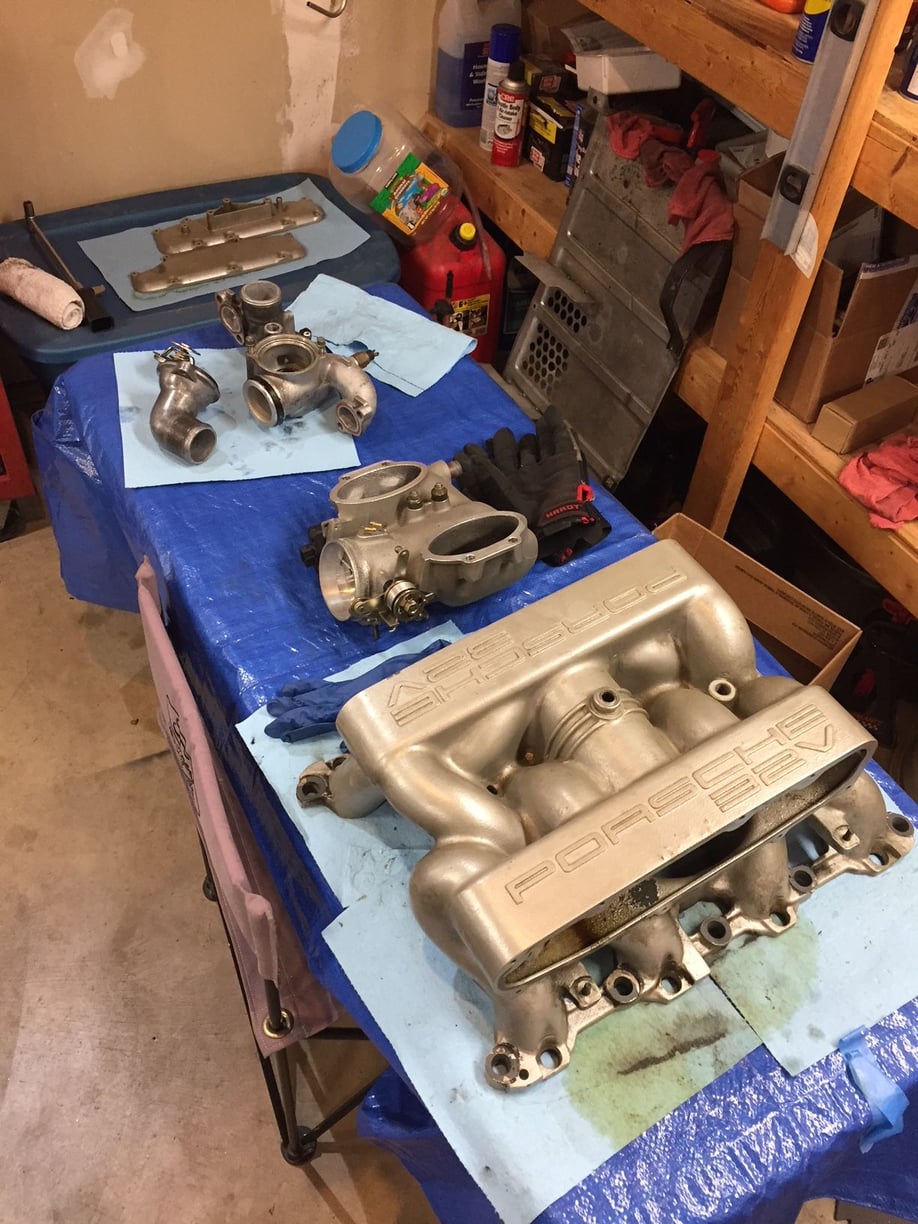
Everything is off the top of the engine now - intake, oil filler, and water bridge. I have had winter leaking from the seal between the water bridge and the block, so it's been on my list for awhile. Glad I pulled it as the big O-rings are shot, as is the internal thermostat housing seal.
Intake still needs cleaning. Will try steam cleaning and brake cleaner as needed.
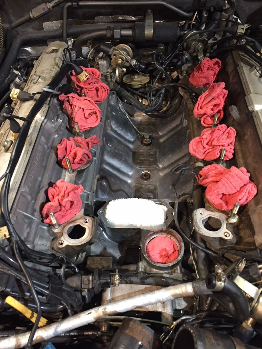
The water bridge came off rather easily. On the left side (of the picture) I placed a 1x1 scrap piece of wood and used a long pry bar to gently lift the water bridge. No fight..lifted right up. I filled the water bridge holes with paper towels after this photo was taken.
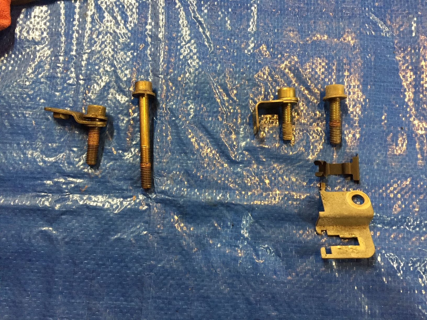
Only two of the water bridge bolts are the same length. Here they are laying in relative position to one another.
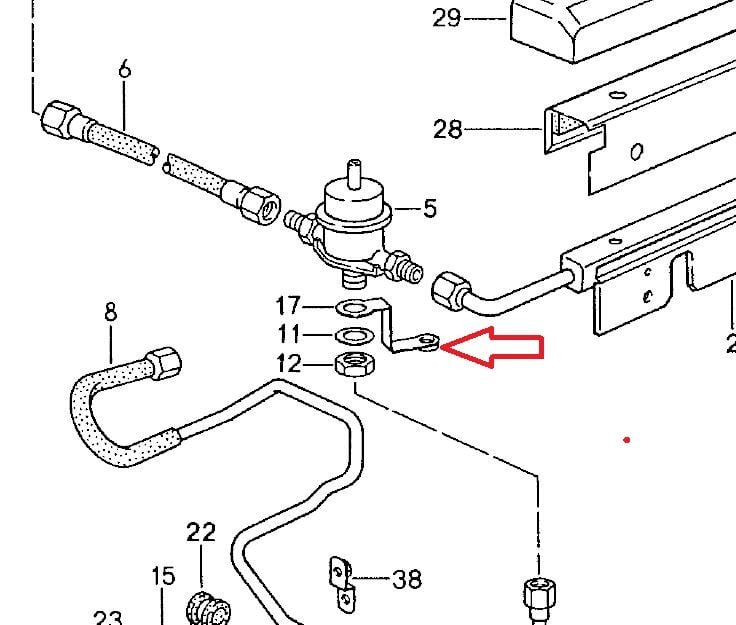
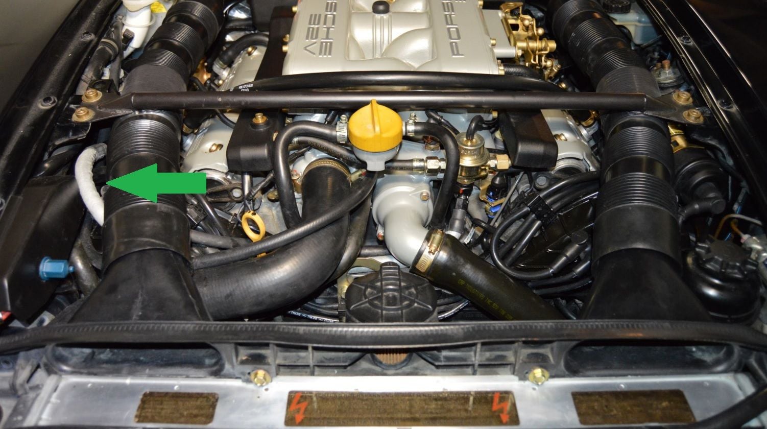
I have a Greg Brown "alternate route" fuel line. It does not use the factory mounting bracket on the right side. Do I need to keep the bracket in place to avoid bottoming out the bolt? The L shaped bracket (right side of photo, left side of engine) didn't have anything attached to it, so is it necessary to prevent bottoming?
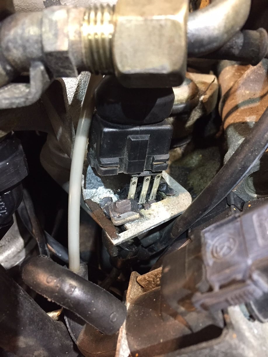
There's only two good times to fix the knock sensor: a TB/WP refresh or a top end refresh. My $.02, replace the connector and the sensor. Alternatively I think Roger also sells a replacement connector for the sensor too, but can't remember. Either way, I would put fresh plastic on both sides of that connection. The demise for that connection is dragging the 14-pin cable through there to remove the TB.
For Greg's fuel line, are you putting on the grey one? I don't remember what I did about putting a shorter bolt where the clamp used to go, so I think you'll be fine.
NoVector - Yes, I have Greg's gray hose. You'll see the hose in the photo showing the top of the engine with all the rags stuffed in it. The GB hose abandons the mounting point where the old hard line came over the cam cover and was bolted to the bracket under the far right (passenger side) water bridge bolt. It's doing nothing on my car now. Thinking of placing a similar thickness SS washer in its place.
Bertrand - I think I have the bracket you are pointing to - but it is held by the far right bolt in the photo. This L shaped bracket is held by the left rear (driver side) water bridge bolt...can't see it easily when installed. This bracket hangs toward the valley...completely hidden. I didn't even see it until I was loosening the bolt and felt it flopping around.
Just replace the knock sensors. Pick the remains out of the harness-end plug connector. The harness-end doesn’t deteriorate unless it’s eff’d with. Do not cut the connectors off of the harness.
There is zero win in replacing the connectors. One pin in each connector is connected to braided shield for the harness. Yes, you can futz with the shielding but, the harness end doesn’t need replacing and the sender end is connected to something you are throwing away.
The knock sensor connectors have nothing to do with the 14-pin jump post connector.
The little L-bracket is a mount for a plastic ‘omega’ clip for the front knock sensor.
For the long Teflon fuel line that replaces the supply line, I just did best-guess routing, and I found that not only do you not need that Z bracket on the left in the photo (passenger/right side), IIRC it actually gets in the way. Mine is in the 'leftover parts' bin labeled in case an SO ('successor owner' - is there such a term?) decides to go back to stock. The bolt torqued to spec and did not bottom.

 03-21-2018, 03:51 PM