When you click on links to various merchants on this site and make a purchase, this can result in this site earning a commission. Affiliate programs and affiliations include, but are not limited to, the eBay Partner Network.
The receptacle in the CE panel that holds the fuel pump relay has all four of its plastic retaining clips broken off. I would like to restore the integrity of that relay seating, and I�m wondering if anyone has ever taken the plunge and swapped out sockets. There are a number of unused sockets on the panel, but y�all know it�s pasta time back there.
Anyone ever braved the unplugging of the grey wires so as to gain access to a relay socket?
1985
Sure. Do it frequently. I "steal" relay holders from junk relay boards.
Semi-retired, as of Feb 1, 2023.
The days of free technical advice are over.
Free consultations will no longer be available.
Will still be in the shop, isolated and exclusively working on project cars, developmental work and products, engines and transmissions.
Have fun with your 928's people!
If you do remove the socket, please be sure to follow up with a post on how to depin the connectors in the socket. I had the same problem with the dual socketed light relay. I struggled for hours and was not able to depin them so I had to JB-Weld the sockets back into the panel. Not pretty but effective.
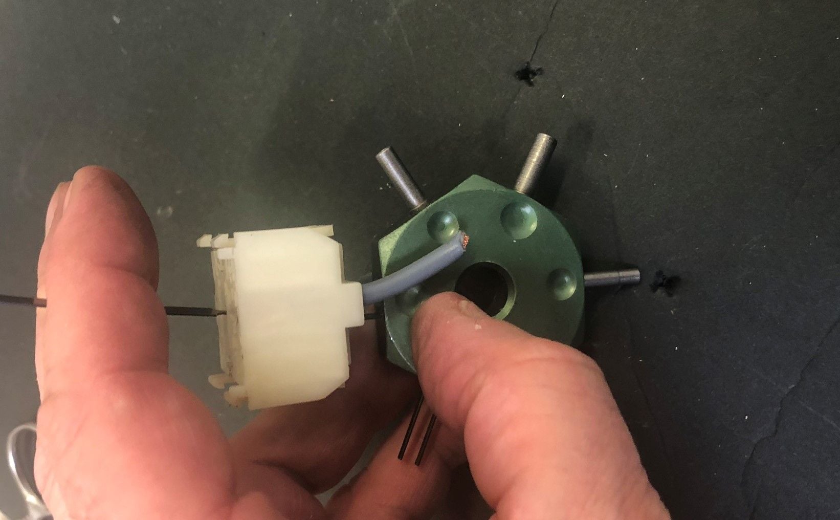
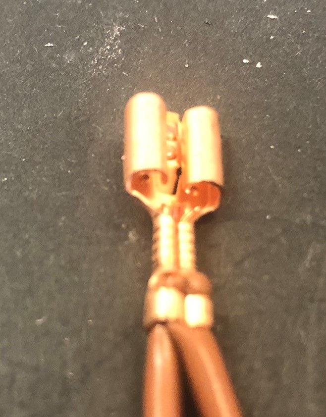
So I pulled the XXVI relay socket and swapped it with the fuel relay socket. I actually had to cut away the protrusions in the frame of the unused socket, because it was very difficult to remove the empty socket without potentially damaging it. Getting the original fuel pump relay socket out was a little dicey. As JSchiller indicates above, it is not easy getting the wiring out of a socket. The copper connector has a very small tab that is angled to go in easy but resist removal. I wasn’t worried (well, a little) about damaging the already-defective socket, so my archeological digging got a little blunt at times.
Yes have done it many times. You need the right terminal tools and a spare socket front/body - the 85+ relay sockets are 2 part items a face and a body.
To remove the socket you need to release and remove the front (to the front) then remove the body (to the rear). Understanding the anatomy makes it easier
Do - Photograph the existing wiring and label the wires before you start. (assume you did)
I use the following tools - they work but require a certain amount of technique - its important to know what you are trying to do:
Broken panel I was disassembling
Tools - Rear (L) Front (R)
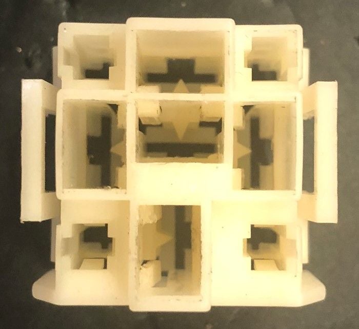
Face plate partially mated - note the face release tabs are on 2 opposite sides (release from the back). To remount sockets - release the face - click body into the panel - re-attach face
Face plate removed Face (B) & Body (T)
Insertion to release tab from front
Tool Usage - Insertion from front (left) and Back (right)
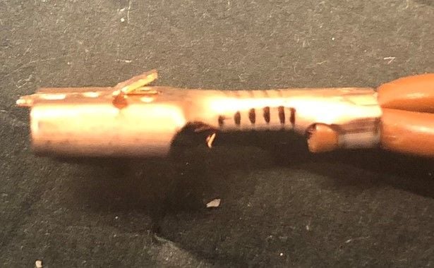
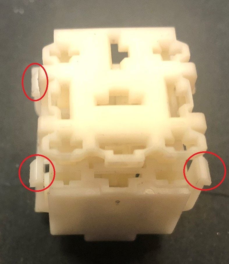
Top View Terminal Removed - 2 plastic locking tabs in the body - lock against the top/back of the rings to stop the terminal pushing out the back of the body
This is the primary retention mechanism
Terminal Side - Locking Tab (this is Not the primary retention mechanism)
Rear view
Terminal Front Face plate fully installed - Red rings show how the face plate corners parts locks the mounting tabs (body to panel) from releasing face plate not fully locked down - allows mounting tabs to be released (from the front or back)
Thank you for popping into this thread. You’ve helped me with electronics for over ten years now and I recognize you to be at the top of the mountain of know-how. Say hi to Ohm for me will ya?
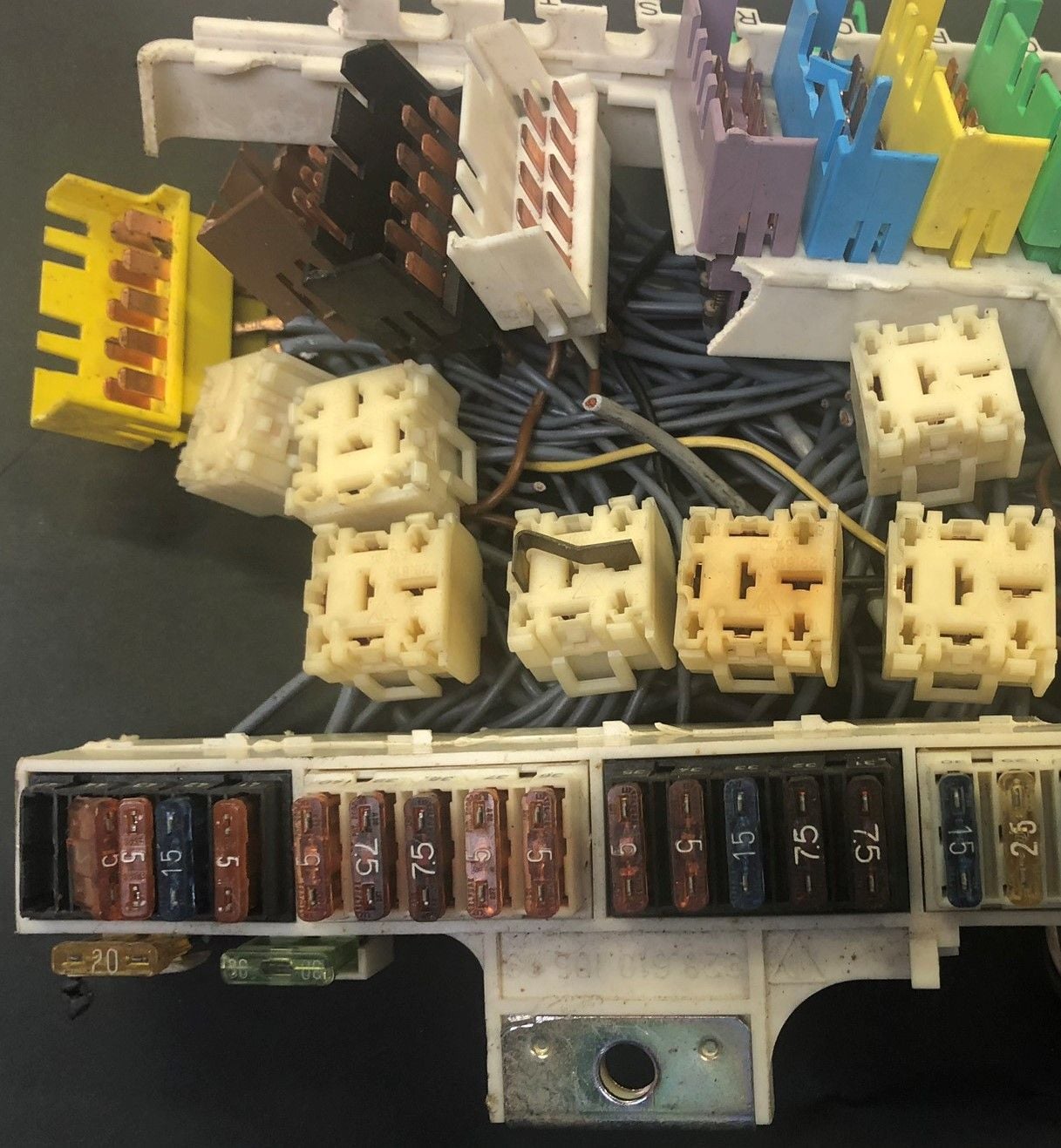
The PO was clearly in the CE panel on our 1985. The second photo shows how a wire from the aftermarket stereo has simply been plugged into fuse slot 22. So too, there are small wires with inline fuses that have been cut - I believe these are part of the central locking system, which doesn’t work.
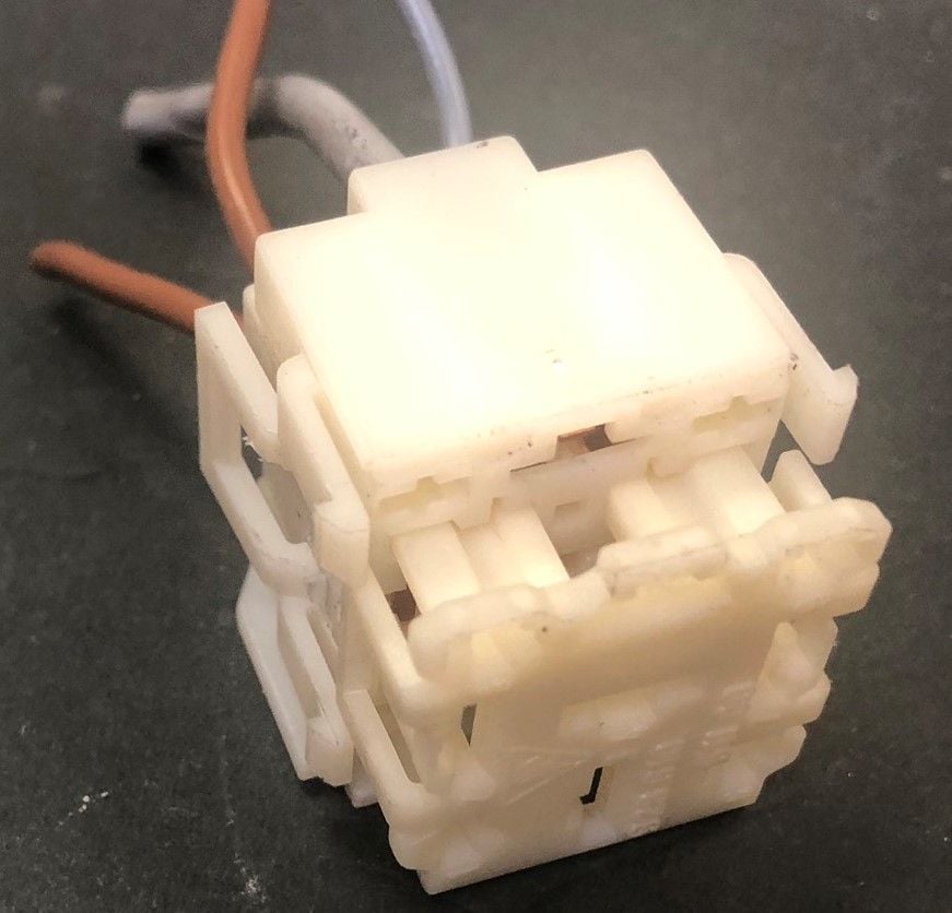
The first photo shows an unconnected four-pin harness - not sure if this is supposed to connect on our 1985 or if it’s a Euro-only.
Before I put the panel back in, I’d love to rectify these issues. Thank you!
Those are the fuses for the door locks - but looks like they might be aftermarket ones (what I've seen before are white/natural nylon)? - you can tidy that up anyway using the ones you have - if there are good fuses the fault in the central locking must be elsewhere. The connection plugged into to the fuse holder is not ideal - I'd remove it then connect properly to the fuse on the back (note there may be an inline fuse holder somewhere else - remove that). Use a 0.25" Quick Disconnect female (instead of male) to connect to the bottom connection (on the back of the panel) for an unused fuse - for an '85 you can use (as most appropriate):
Fuse #3 - the top connection (power input) is Accessory (X)
Fuse #9 - the top connection (power input) is Ignition (15)
Fuse #22 - the top connection (power input) is Battery (30)
I don't know what the 4 pin connector is for (anyone with an 85 know?) - what are the colors - I thought Red/Red/Black/Blue? That didn't help in a quick look over the likely suspects
Those are the fuses for the door locks - but looks like they might be aftermarket ones (what I've seen before are white/natural nylon)? - you can tidy that up anyway using the ones you have - if there are good fuses the fault in the central locking must be elsewhere. The connection plugged into to the fuse holder is not ideal - I'd remove it then connect properly to the fuse on the back (note there may be an inline fuse holder somewhere else - remove that). Use a 0.25" Quick Disconnect female (instead of male) to connect to the bottom connection (on the back of the panel) for an unused fuse - for an '85 you can use (as most appropriate):
Fuse #3 - the top connection (power input) is Accessory (X)
Fuse #9 - the top connection (power input) is Ignition (15)
Fuse #22 - the top connection (power input) is Battery (30)
Alan
Alan - continued thanks!
I will run the rogue radio wire into the bottom of fuse #22. Your fuse diagram (ala 928sRUs) is hugely helpful.
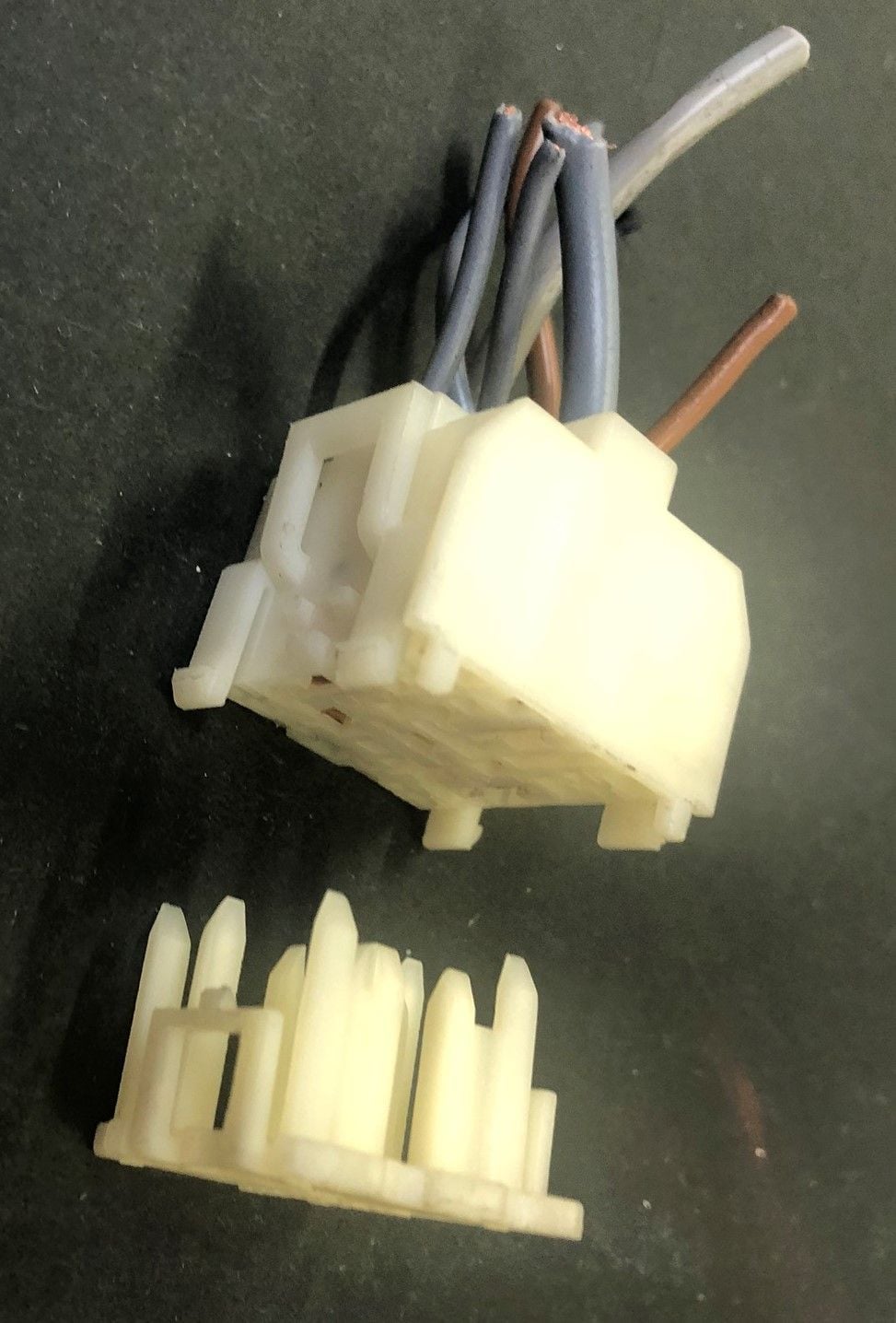
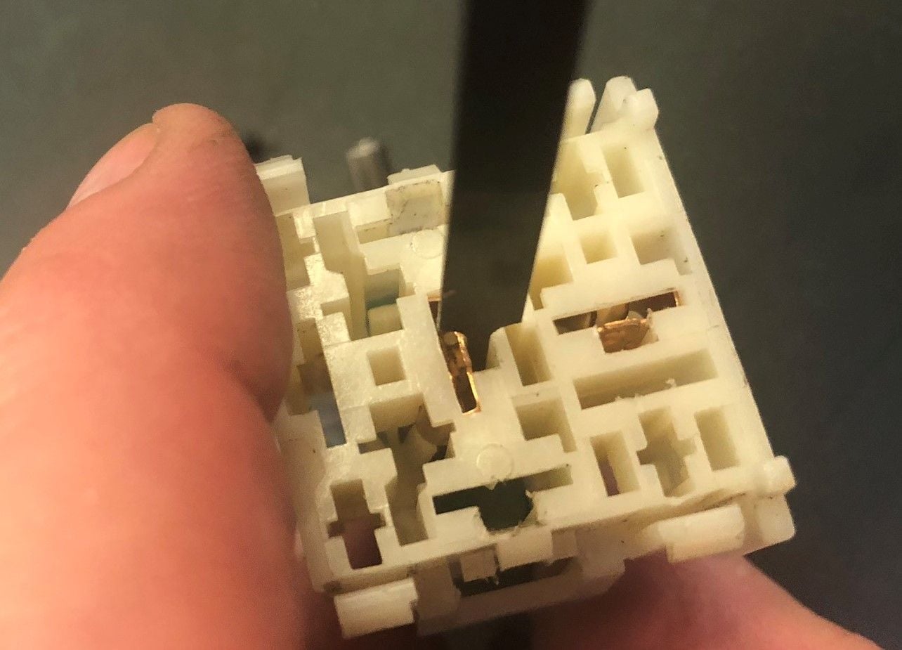
Since I�ve pulled the CE panel, I�m pulling the recirculation box as well. In doing so, I have discovered another wiring harness that�s been meddled with. It is an eight pin (4x2) harness that has a white, two-pin connector with it. A PO has jumpered pins 5 and 7 on the larger. They come in through the firewall, it appears. I see no receptor connection for either. If they were vestigial, why would pins be jumpered?
The main alarm connector IS an 8 pin but Jumpering 5 & 7 doesn't seem to make much sense (jumping pins 1 & 4 restores the EZF function disabled by the alarm). If it is for the alarm - there must be other changes to compensate.
The alarm wire colors are
Pin Color
1 - Yellow
2 - Black
3 - Brown
4 - Black/Red
5 - Red/White
6 - Red/Black
7 - Brown/White
8 - Red/White
If the 2 pin one is Brown & 2x Red wires - it may be for the glove box switch/light.

 07-16-2020, 11:36 PM