When you click on links to various merchants on this site and make a purchase, this can result in this site earning a commission. Affiliate programs and affiliations include, but are not limited to, the eBay Partner Network.
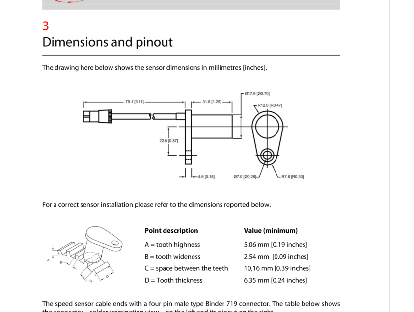
I also looked at the AIM sensor, but it appear too narrow, based on the drawing ( Diameter looks to be 15mm). However, appears to be made by Honeywell, so that may be another lead for sensors.:
I also looked at the AIM sensor, but it appear too narrow, based on the drawing ( Diameter looks to be 15mm). However, appears to be made by Honeywell, so that may be another lead for sensors.:
It looks like that drawing says the diameter is 17.90 mm, which looks pretty darn close.
I haven't had a finger on the pulse of this thread, buts just read through it. Instant thought: Beware trying to "machine" the center pin. They tend to be sintered rather than a cast, extruded or forged part, and need a lot of care especially if you decide to adjust the shape. The risk is that there will be a fracture up higher inside the plastic shell. You won't see it, and the piece will will no longer function. The coil will still show correct Ohms so no apparent reason for not working. Impact damage seems to be a primary killer of the sensors. It used to be from accidental contact/impact with the toothed ring, but maybe that's better these days. Cable and connector damage is similarly popular.
You are right. I was reading the R12 below and to the right as radius, but that is wrong. Good catch.
Still too short though. OE Rear ABS Length is about 46.75mm. AIM Length 31.8 mm.
For an induction sensor, I think that is way too much of a difference.
Had time to look at this further.
Dealing with the rear sensors first.
I have found an alternative that seems in good supply. However a few questions.
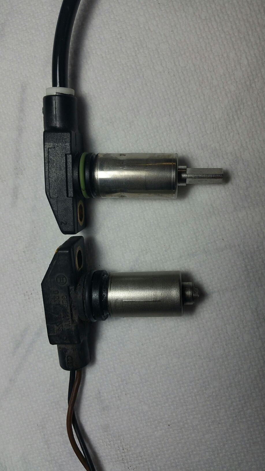
Diameter is the same - bolt location is the same - the top plastc round section with the O ring is smaller but fits. A larger O ring should solve this issue.
Two wire - black and brown so that should make connection easy.
So the problem is length. The small section of metal at the bottom is about 10 mm too long. This is the magnetic part.
Seems solid material. Can this be cut down in length by 10 mm and still work?
Coming back to this option, couldn't you just shim it 10 mm instead of machining it down (with all the problems that entails)? There isn't unlimited space in that area, but 10 mm doesn't seem like that much.
Dr. Bob,
The bottom sensor is what the 928 sensor looks like. The upper sensor is from another car.
My question would be: could the new sensor be taken apart to machine or swap the tip to the shorter version and decrease the opportunity to damage any other part of the sensor?
Also, does anybody have a pin out diagram for the ABS controller unit and connector? The wiring diagram in the WSM doesn't exactly achieve what I need - which is to identify the 2 pins that correspond to each of the 4 wheel sensors and measure resistance and voltage.
A bonus question: there doesn't appear to be a steering wheel input to the system. Is that correct? I think most modern cars use that to determine the differential in wheel slip due to turning.
Leveraging the miracle of Amazon Prime's liberal return policies and huge inventory, I ordered several ABS sensors that looked like they _might_ be useful in our search. I will test and report back.
Leveraging the miracle of Amazon Prime's liberal return policies and huge inventory, I ordered several ABS sensors that looked like they _might_ be useful in our search. I will test and report back.
Excellent, I'm excited to see the results. It looks like I am in need of 2 rear replacement sensors.


 02-12-2018, 08:22 PM