When you click on links to various merchants on this site and make a purchase, this can result in this site earning a commission. Affiliate programs and affiliations include, but are not limited to, the eBay Partner Network.
I have thought about that. To be honest, I feel that is a Pandora's Box that I don't want to open. I DO want LSD for the Red Witch. However, the existing differential will go right back in with no adjustments needed.
To put LSD in:
-purchase a used LSD, which are not cheap by any means
-any used LSD will need to be rebuilt. There was a rebuilt early LSD on Rennlist or one of the 928 FB groups recently for something in the neighborhood of $750, and that was a great deal. That gives an idea of how much more it will be to rebuild a used unit.
-As part of the rebuild, new differential side bearings will need to be installed, which means replacing the bearing races in the side bearing caps.
-ALL the adjustments/clearances/etc... will need to be redone for PROPER installation of the LSD into the housing. Meaning the pinion gear assembly will have to come back off the transmission to change its shims accordingly. Since it will be coming out again, might as well replace the pinion bearings.
Am I a crybaby for thinking this way? Yes. My uncalibrated Money-O-Meter suggests putting an LSD in the Red Witch will run somewhere around $2000-$2500, if you take into account ALL parts and labor. That is money I would rather spend elsewhere on the Red Witch.
Also...one of my long term goals is to purchase one of Greg Brown's NOS A28 transmissions. He has an A28/09 Euro spec M251 Special Option box with LSD, steeper 2.54:1 final drive, and higher 2200-2600 stall speed torque converter. I REALLY want one of those. Where I live, there really is no area available for sustained high speed cruising. So, the benefit of 2.20:1 final drive is no use to me. I am willing to trade off some top end for better take off and response with the steeper 2.54:1 final drive.
Yes, I am doing good work to my A28/07 transmission. However, it is still an old transmission with 168,*** miles on it. Last year, I had Greg Brown quote me a full, proper overhaul of this transmission. Somewhere in the neighborhood of $3500-$4000, all things depending. I can live with that. So, the NOS box is only around $1500 more. Money better spent on the NOS box.
So, to make this short, I have thought about adding LSD, but am not going to at this time due to cost and complexity. Make sense?
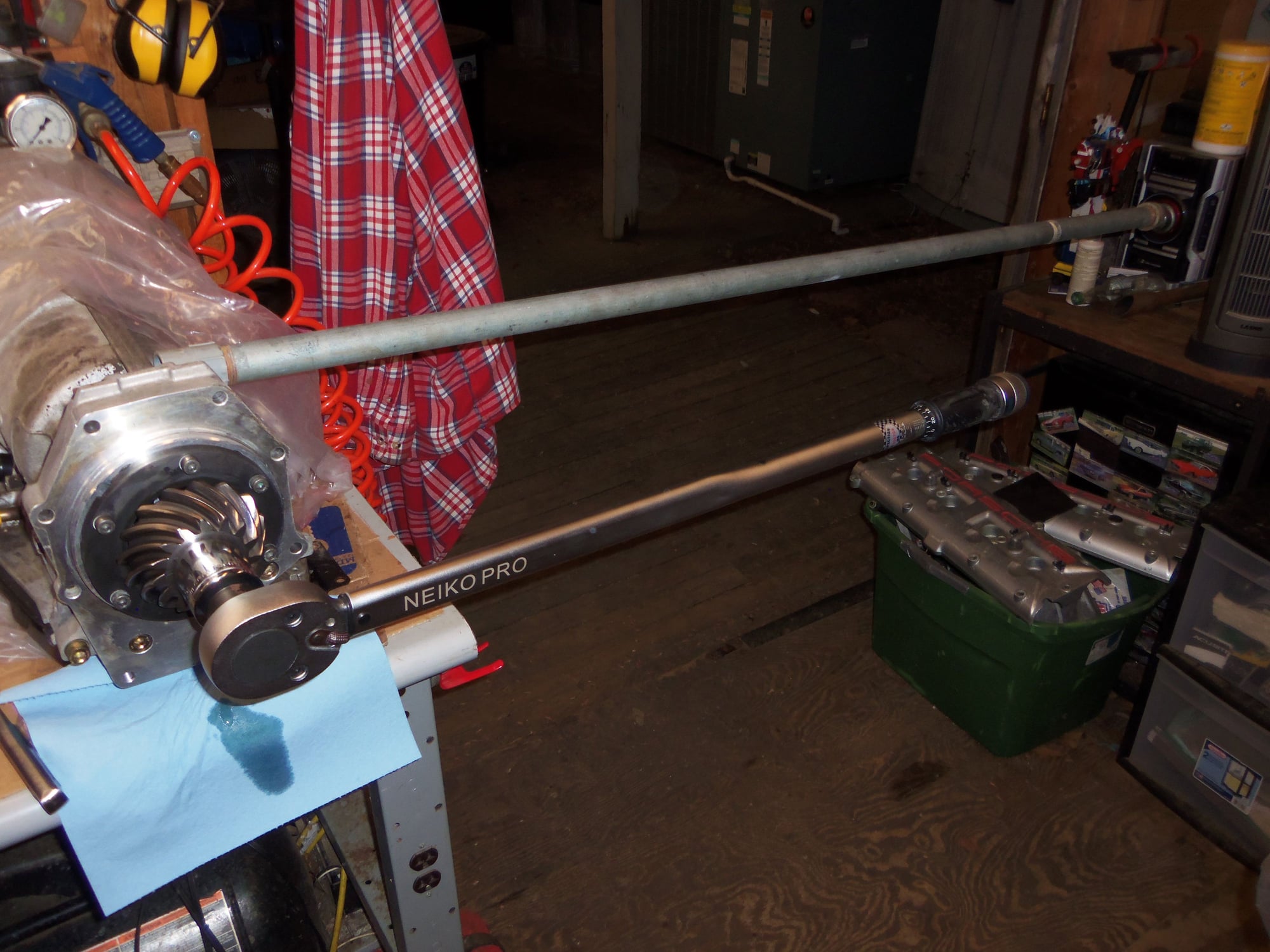
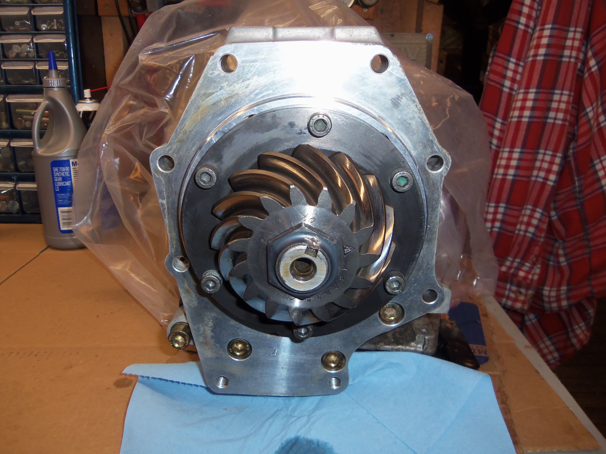
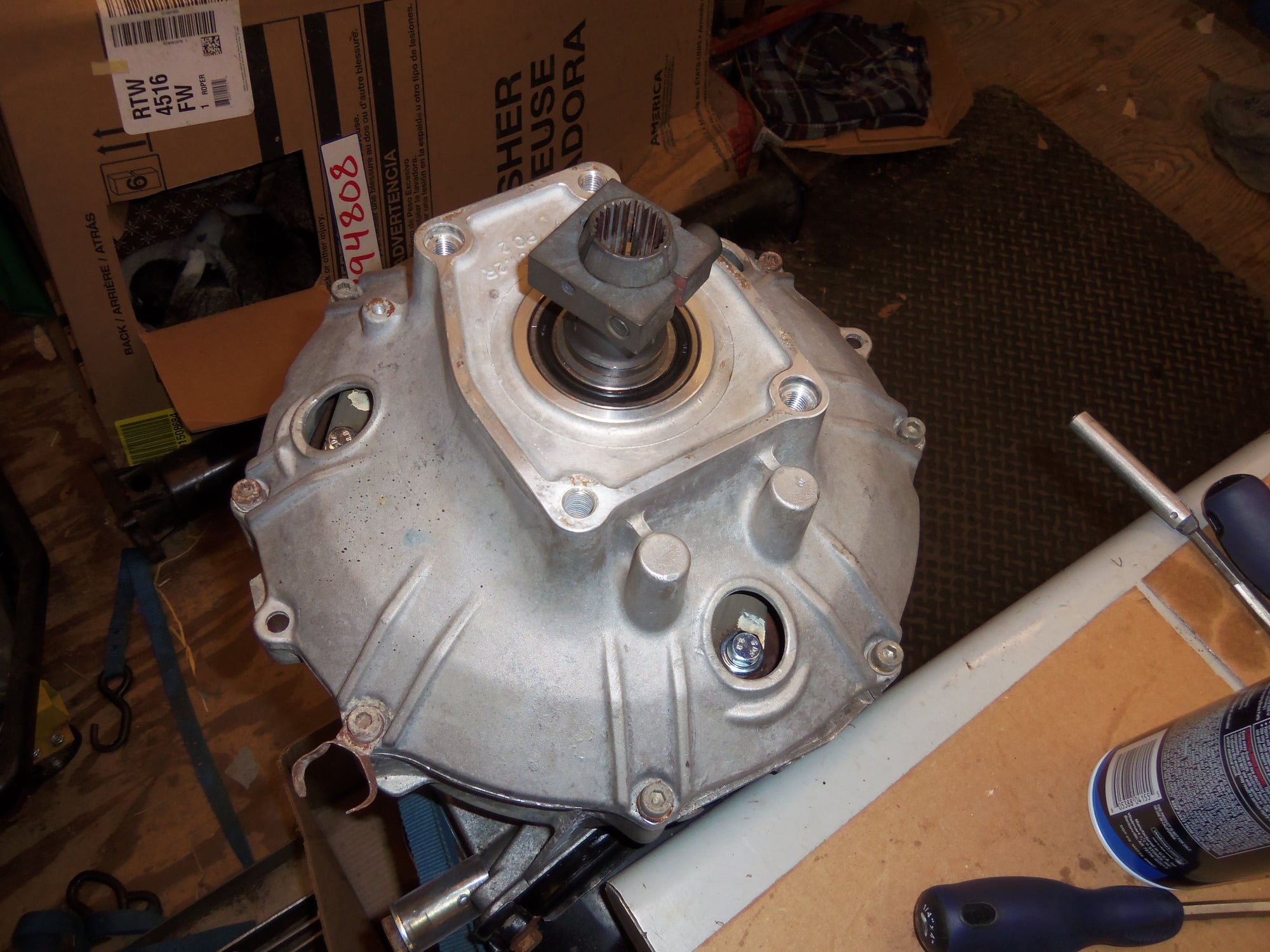
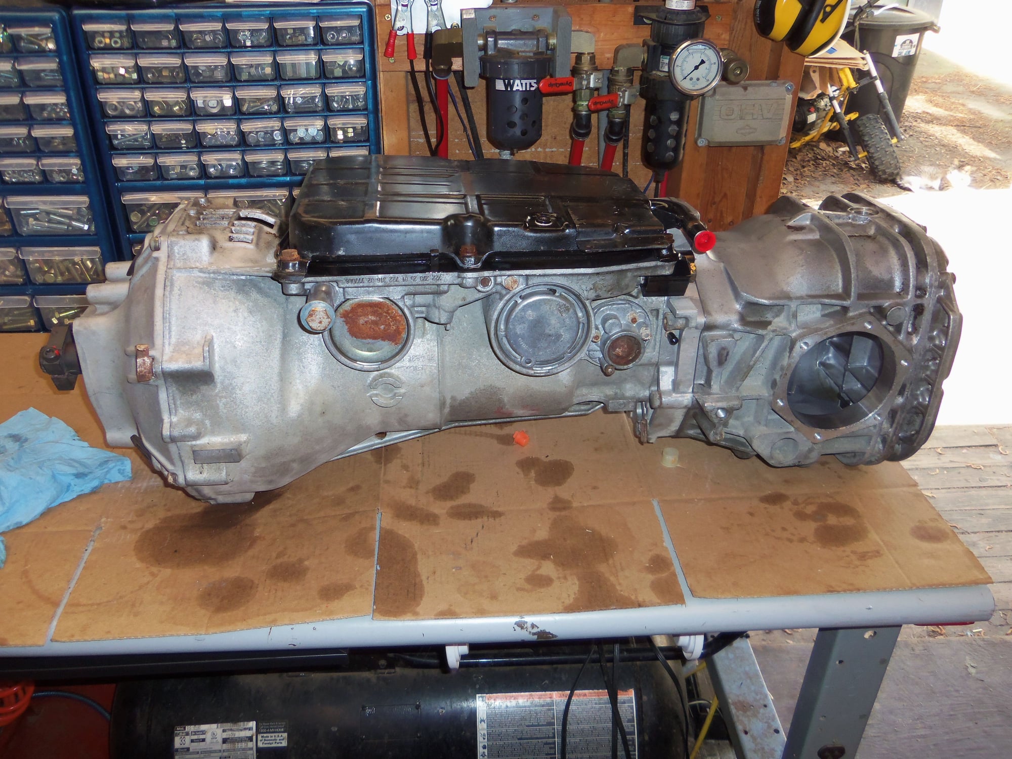
Alright, onto removing the pinion gear assembly to gain access to the separator plate.
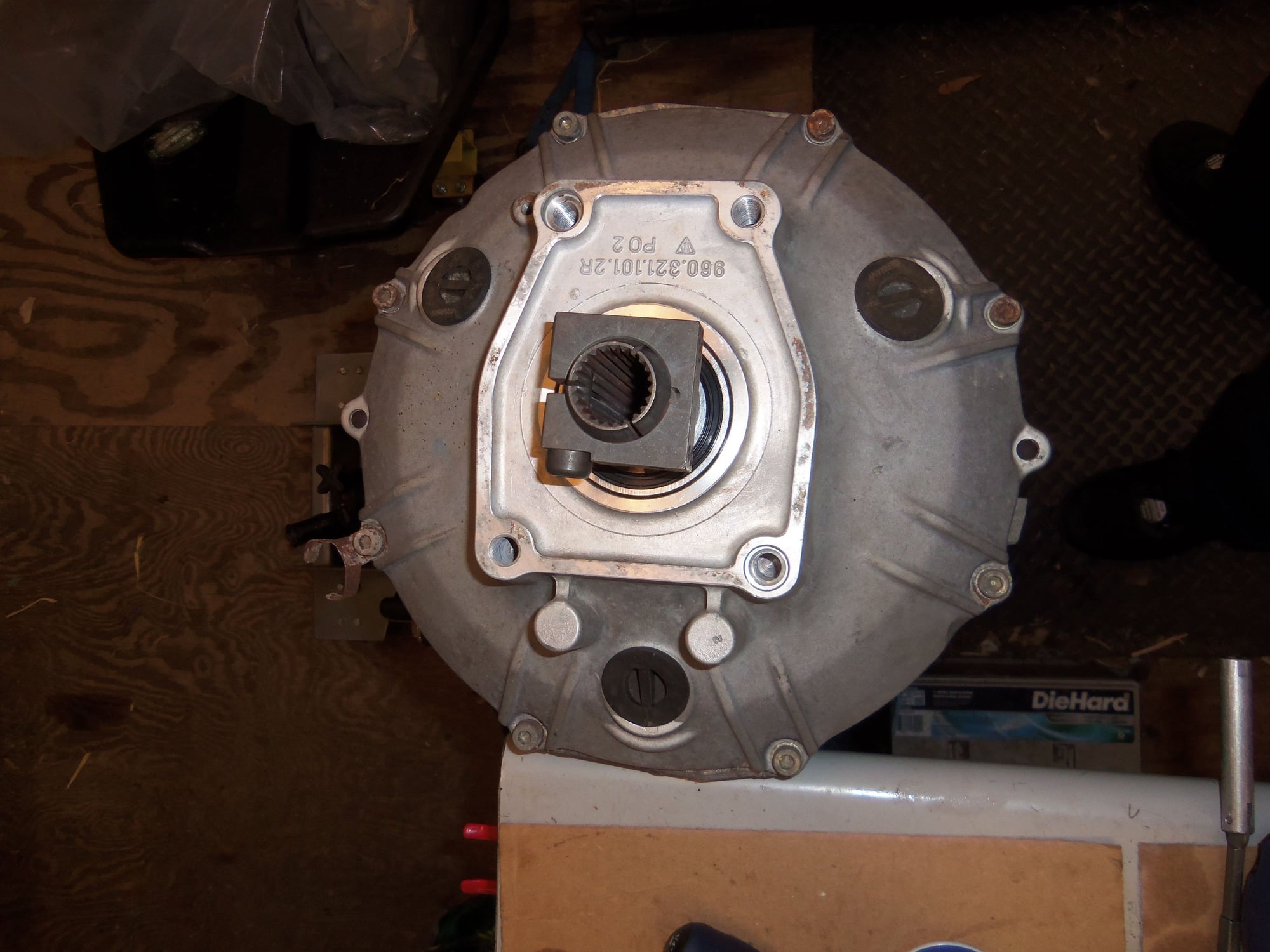
Had to chisel off the upset part of the retaining nut out of the keyway in the output shaft of the transmission. Not wanting to mar the pinion gear teeth in ANY way, I did not hold them and instead used my impact to remove the nut. It put up a fight, but came off. Once the retaining nut was off, it was a matter of removing the six socket head screw that secure the pinion gear/bearing assembly to the separator plate. According to WSM Volume 3, often a puller is needed to remove the pinion gear/bearing assembly from the transmission output shaft. I was very pleased that mine came off the shaft after application of some pulling force via my hands. Very good.
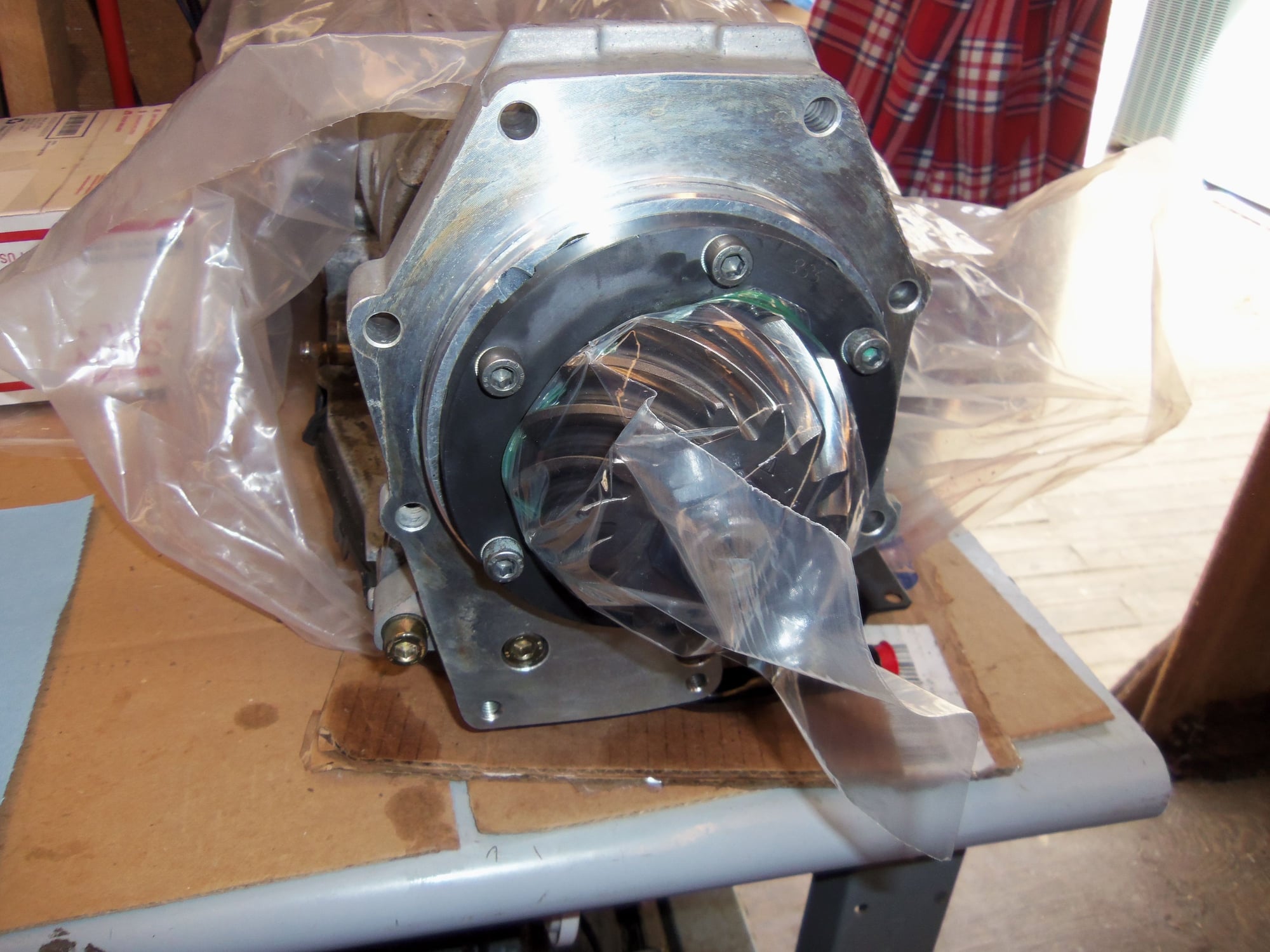
After limited disassembly, the pinion gear/bearing assembly was THOROUGHLY hosed down with brake cleaner. I wanted to remove the slightly rusty looking residue from the female splines inside the pinion gear. Then, the bearings were lubed with gear oil and rust preventative oil sprayed on the gear teeth. Into a heavy plastic bag it went until reassembly.
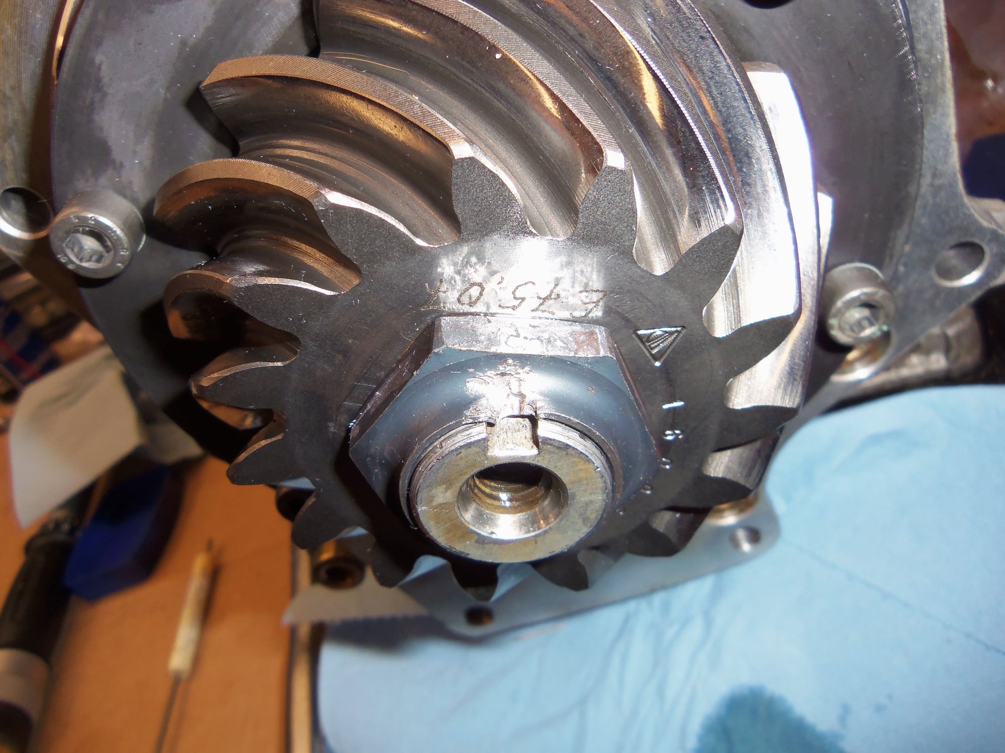
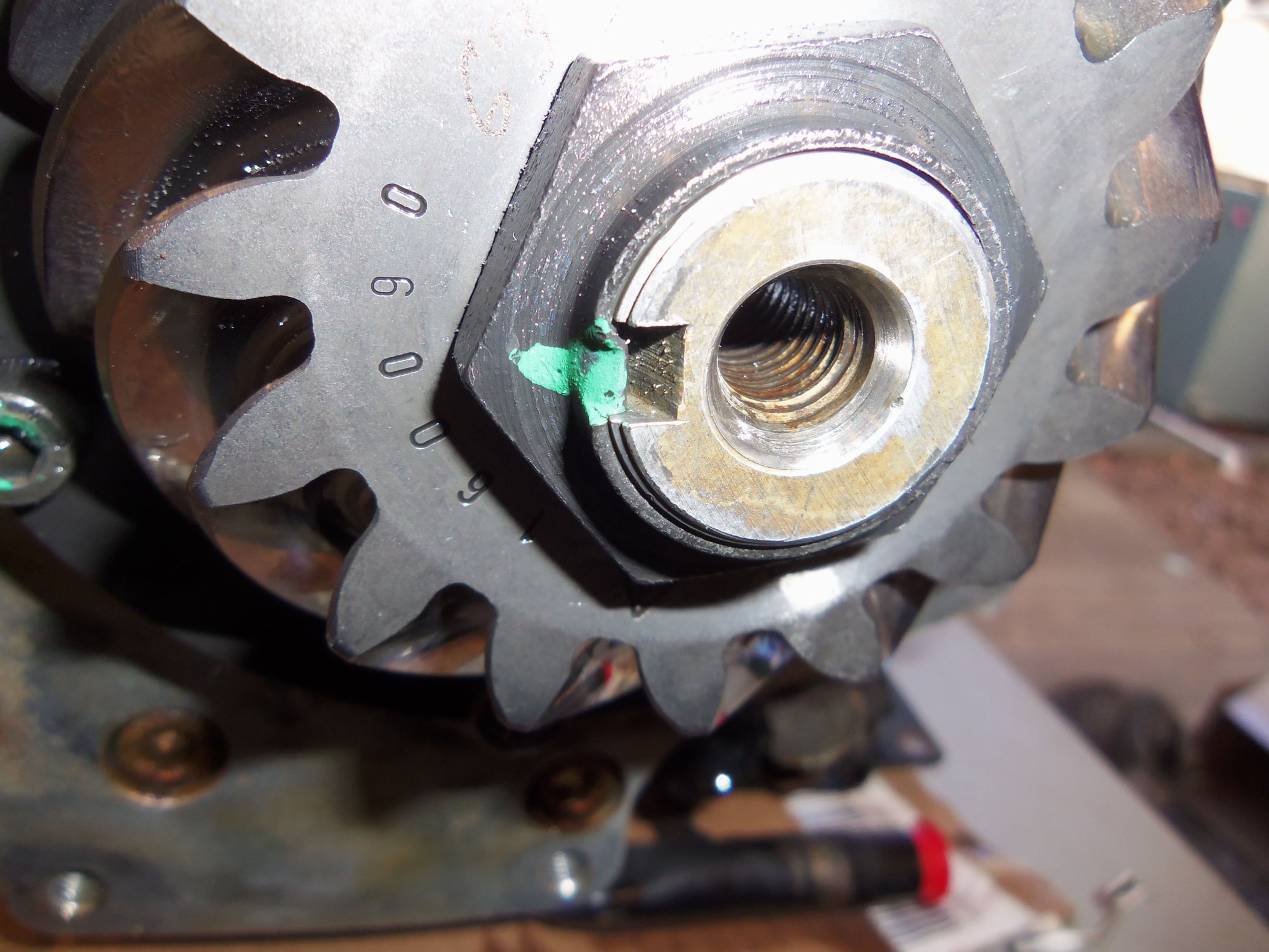
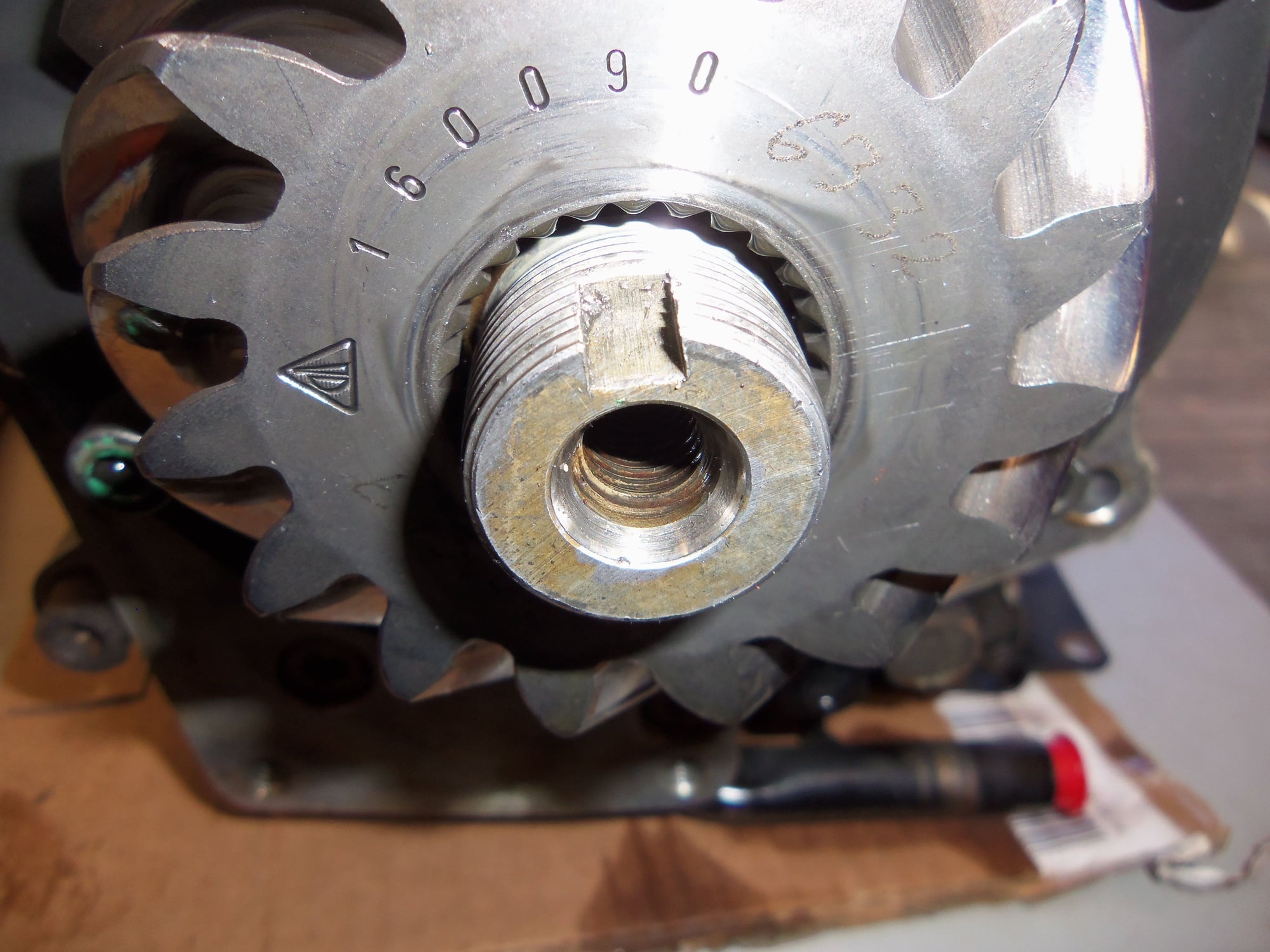
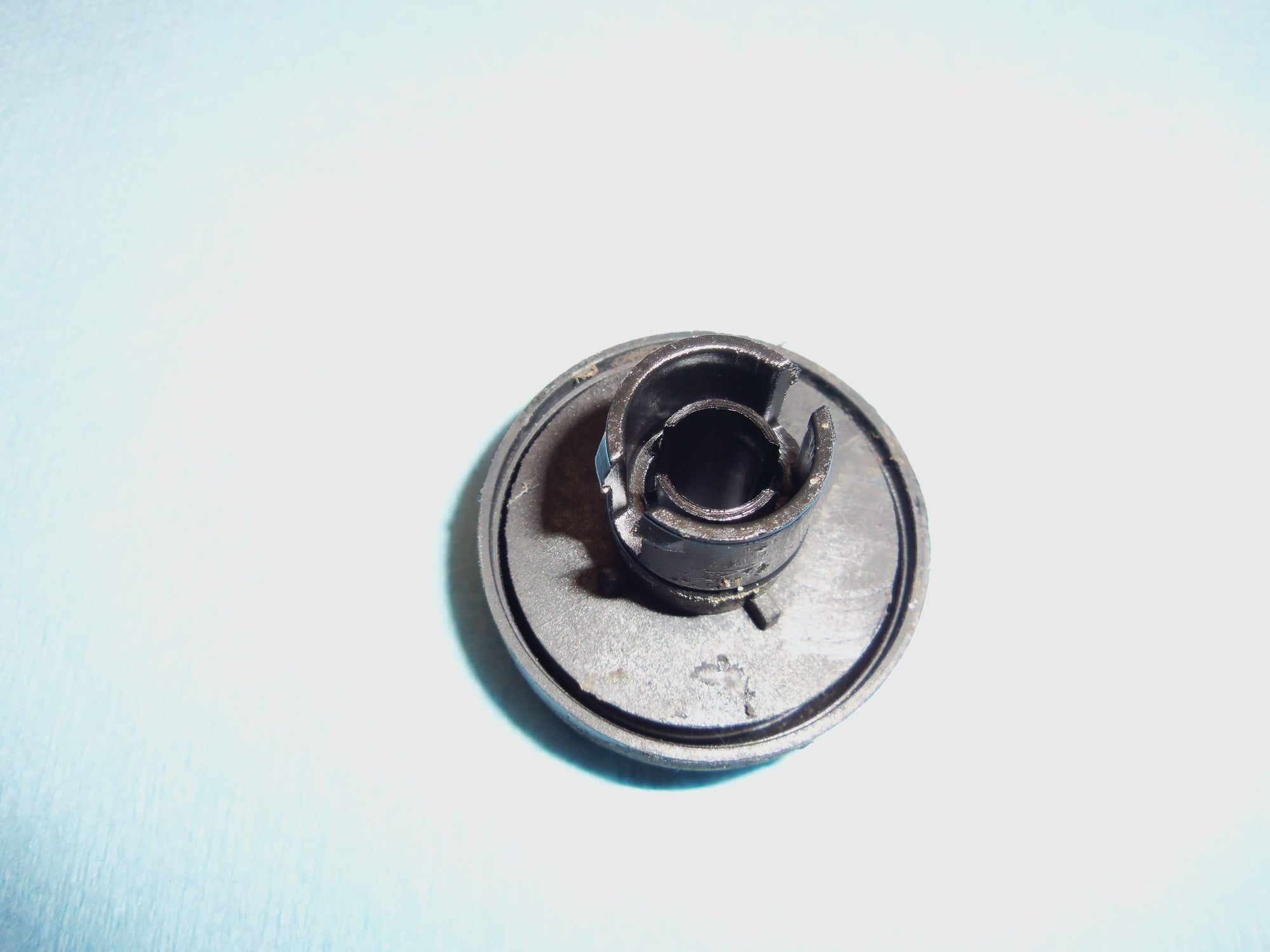
Pinion gear to transmission output shaft retaining nut. Note the upset portion that I had to knock out of the shaft keyway.
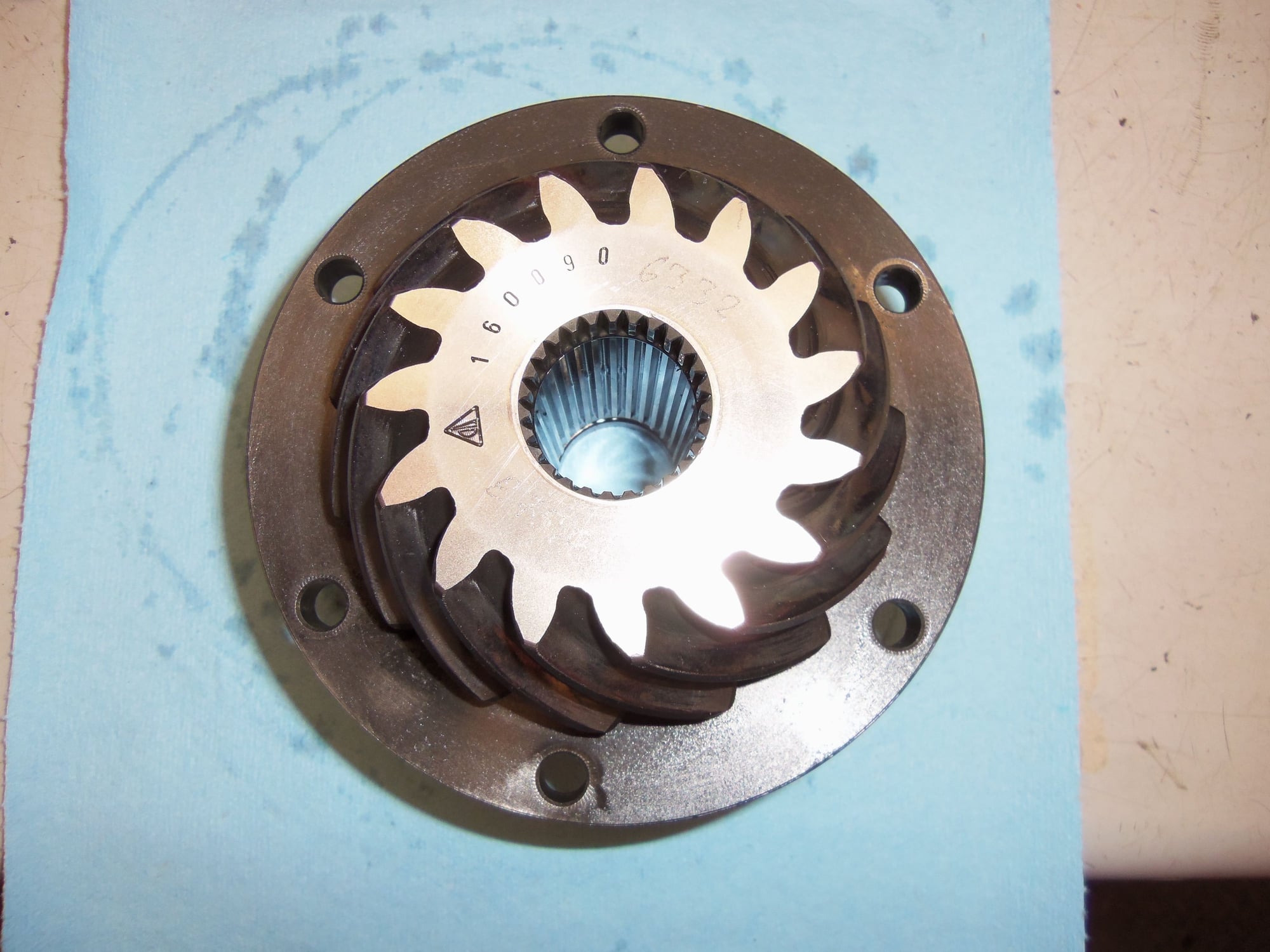
Nut removed, note the stamped and engraved markings on the pinion gear.
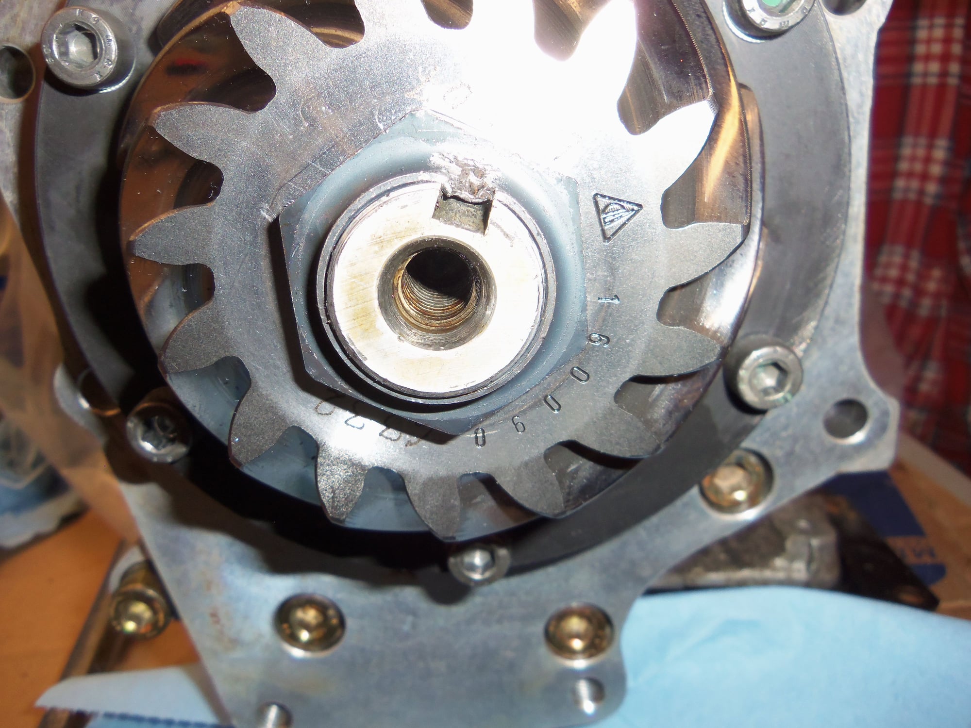
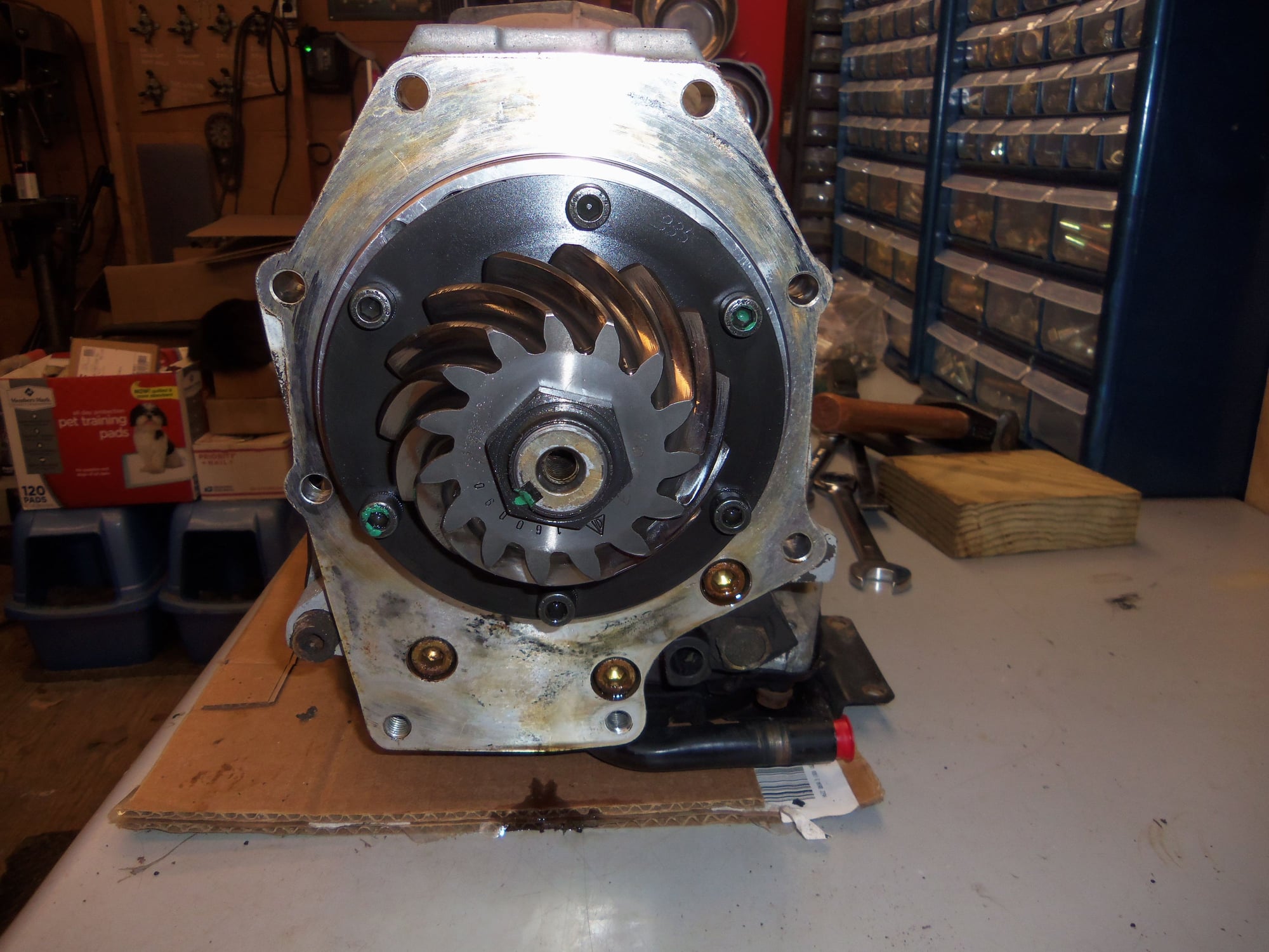
Six socket head bolts that secure the pinion gear/bearing assembly to the separator plate.
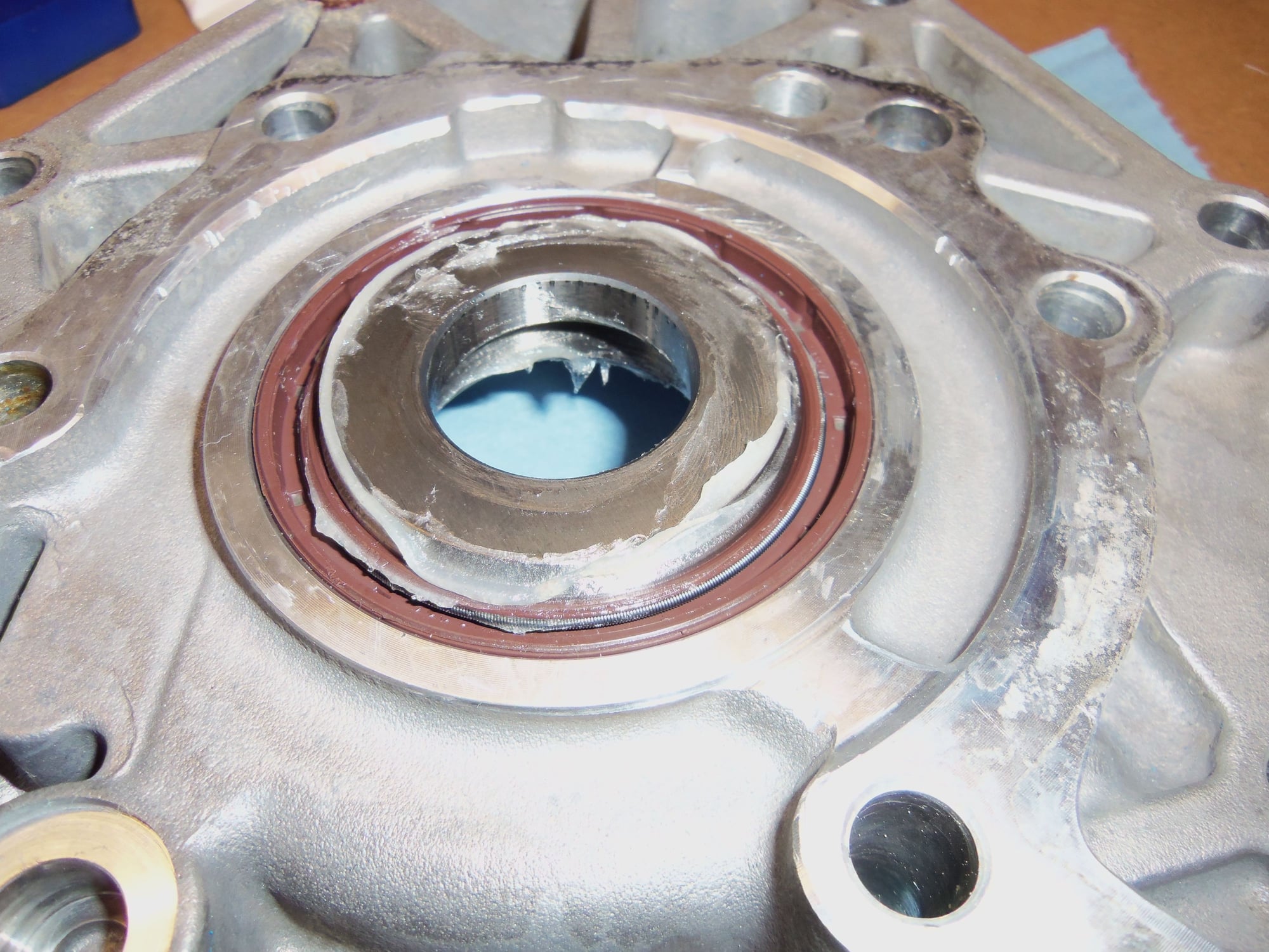
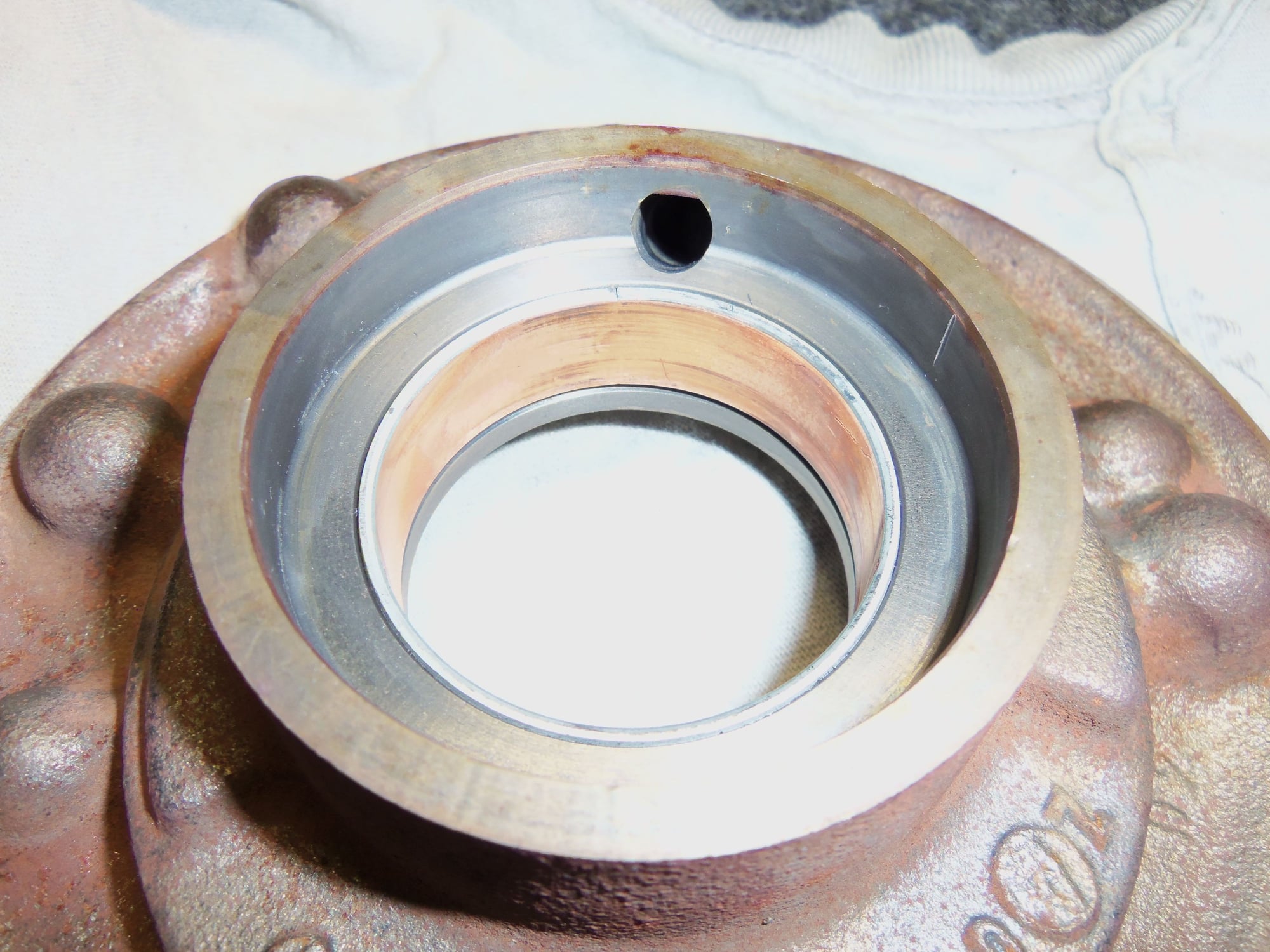
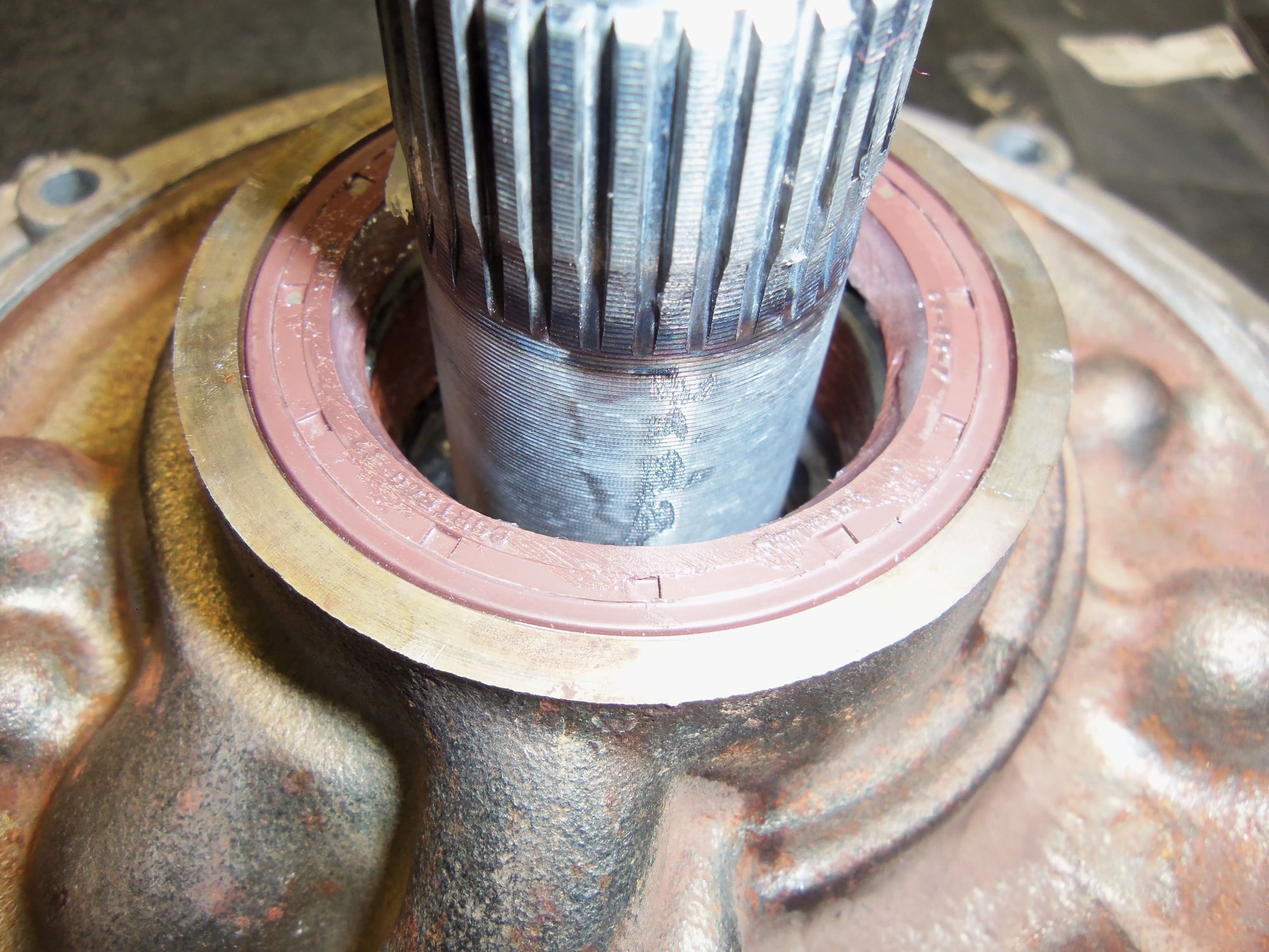
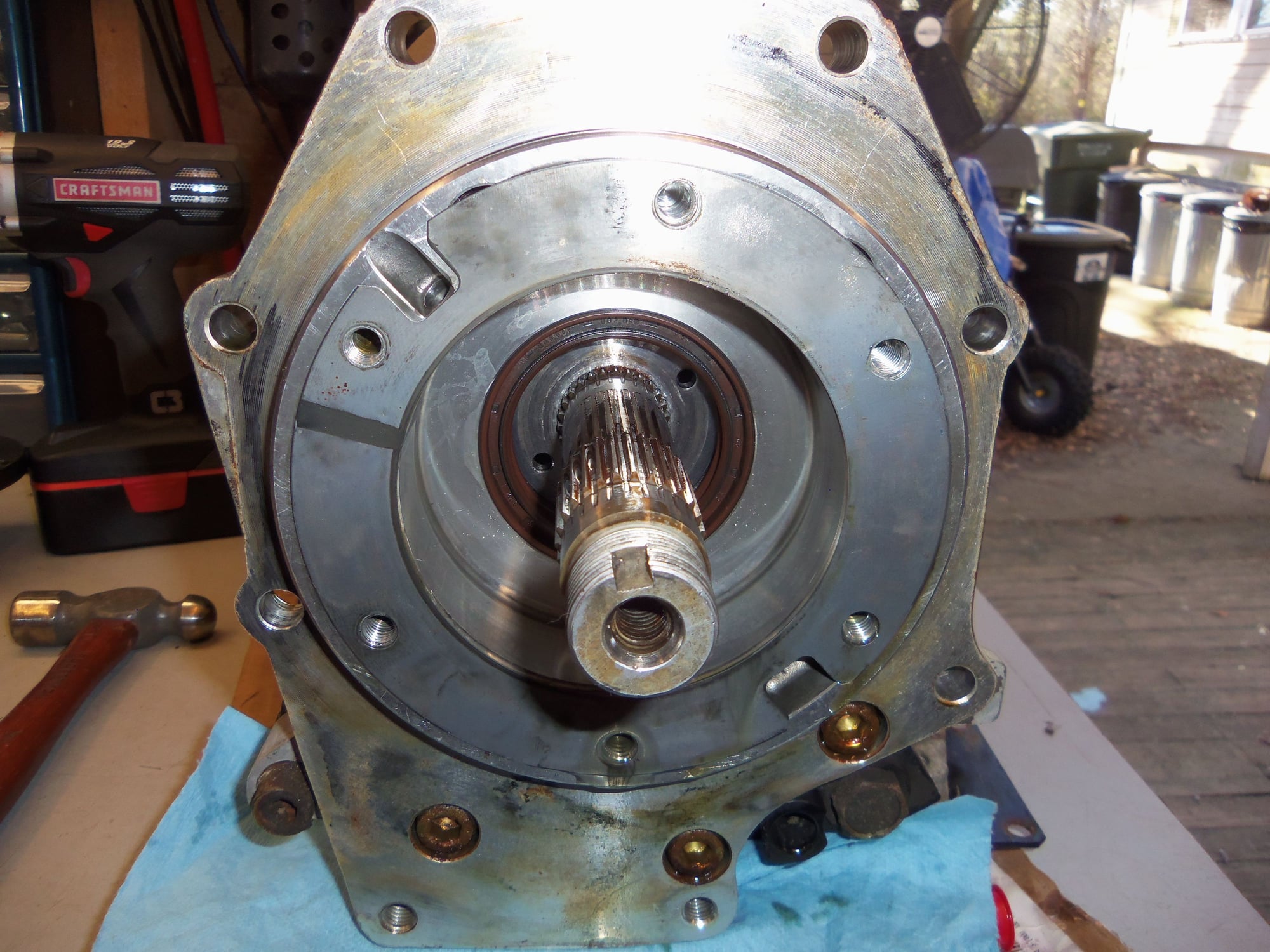
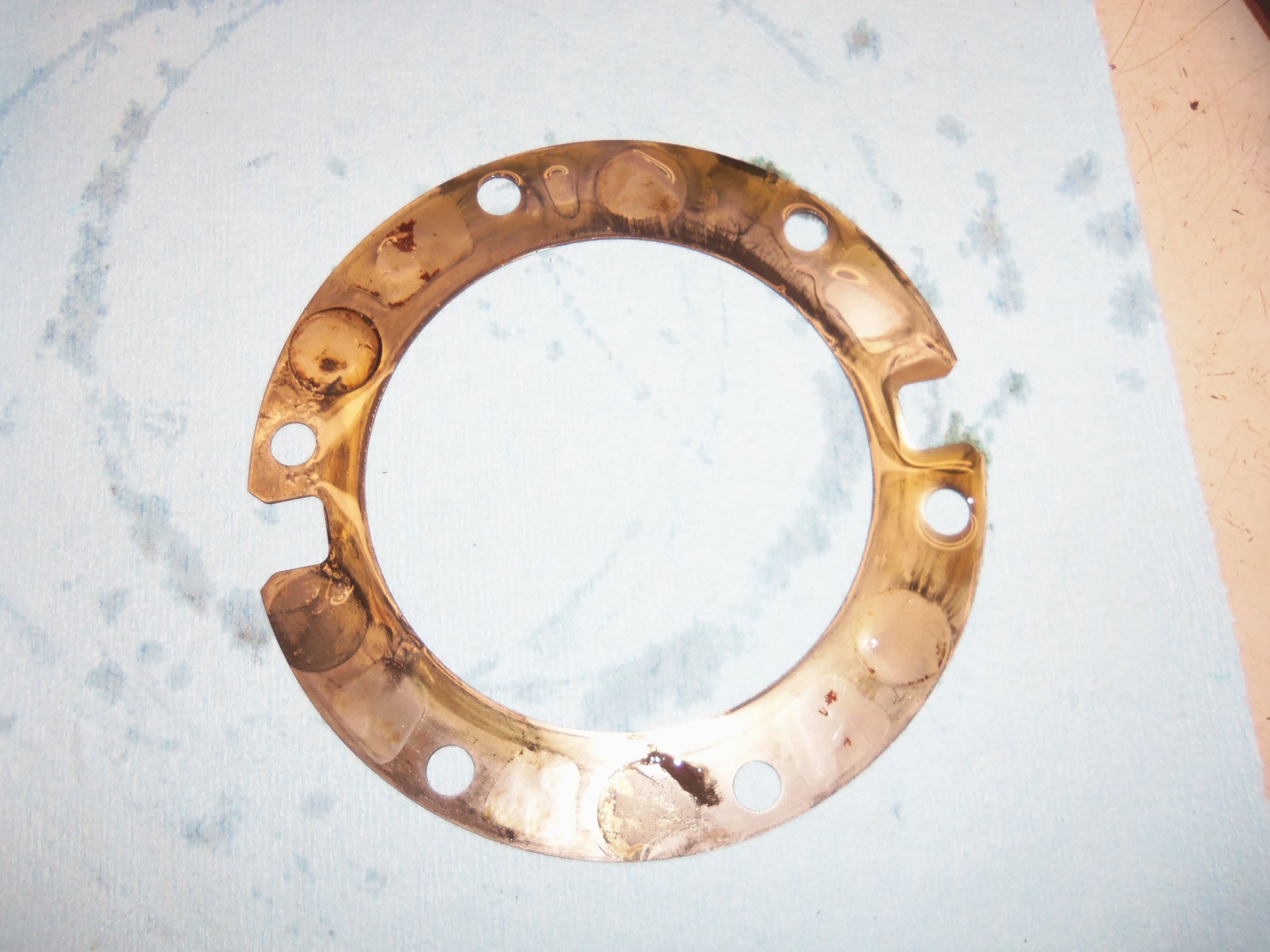
Shim behind the pinion gear/bearing assembly. Note the brown radial seal. That one was seeping gear oil out of the differential.
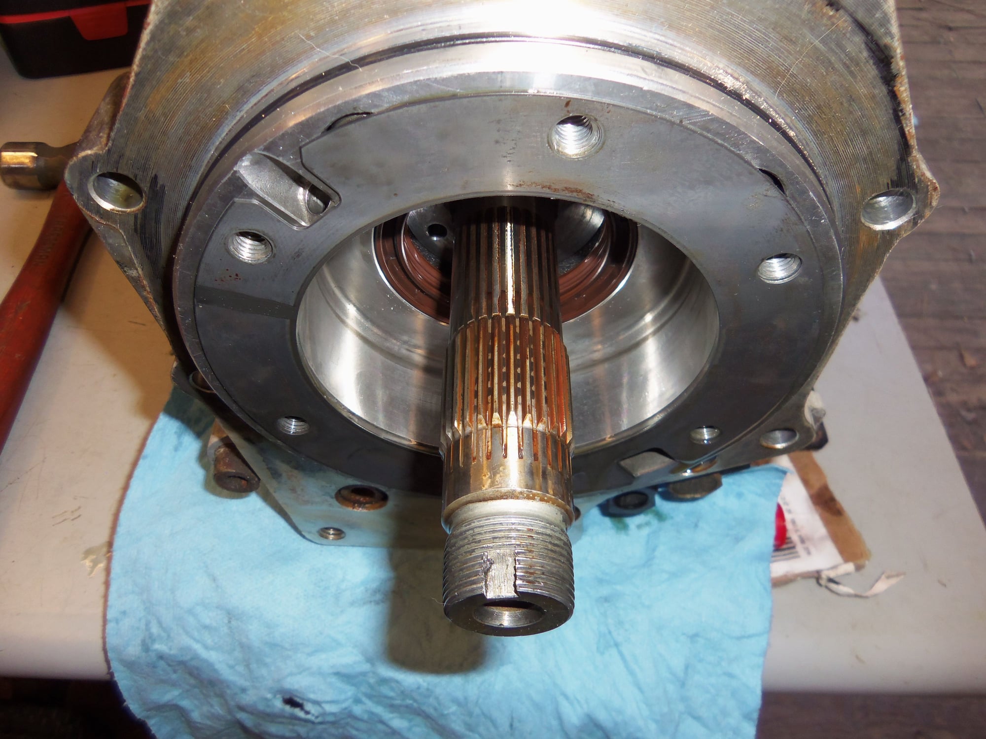
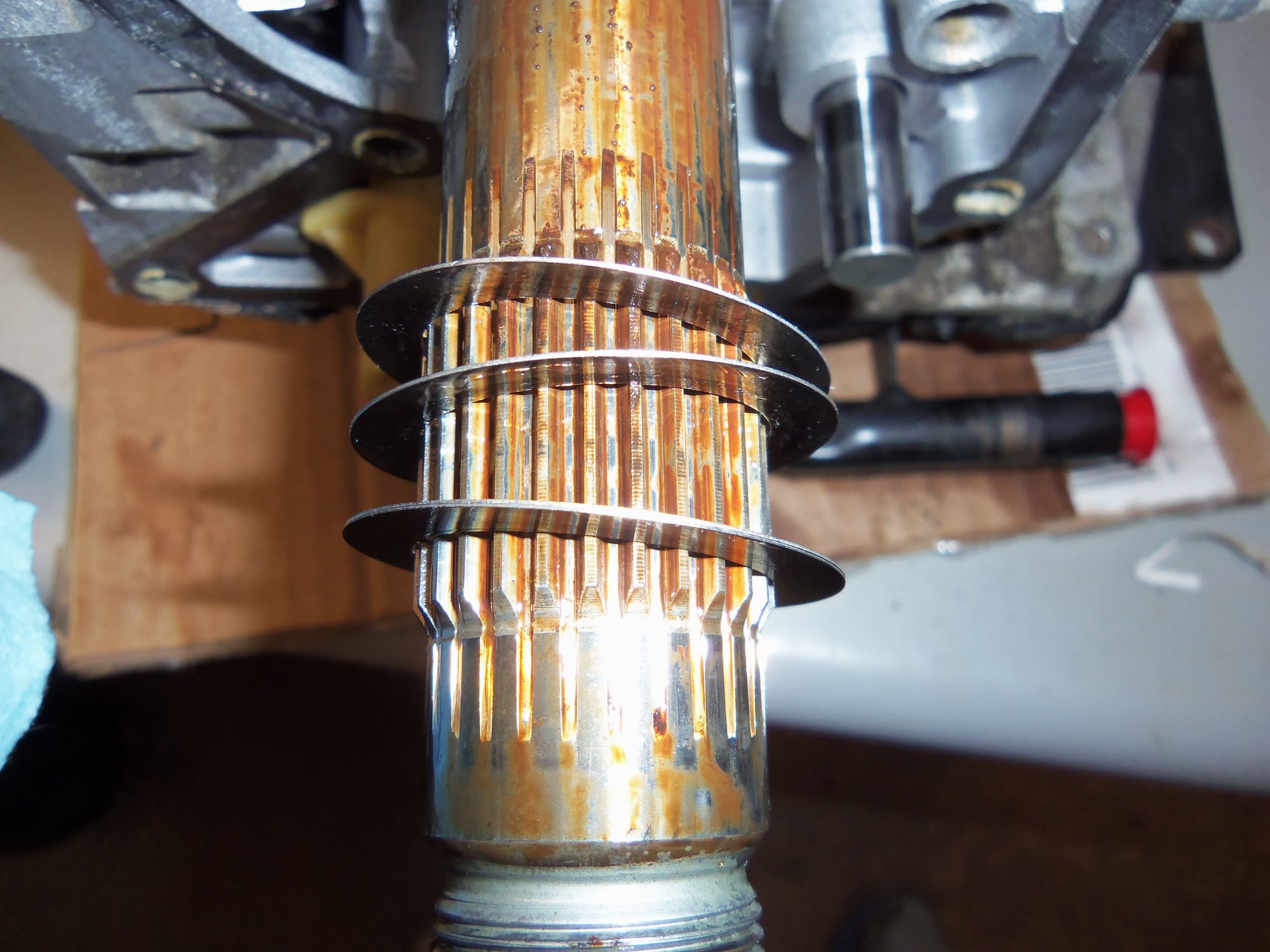
Splines on transmission output shaft engage the female splines inside the pinion gear.
Shim removed to show the five socket head bolts behind it, and three more below. These secure the separator plate to the back of the transmission casing.
Shim for pinion gear/bearing assembly.
Top of pinion gear.
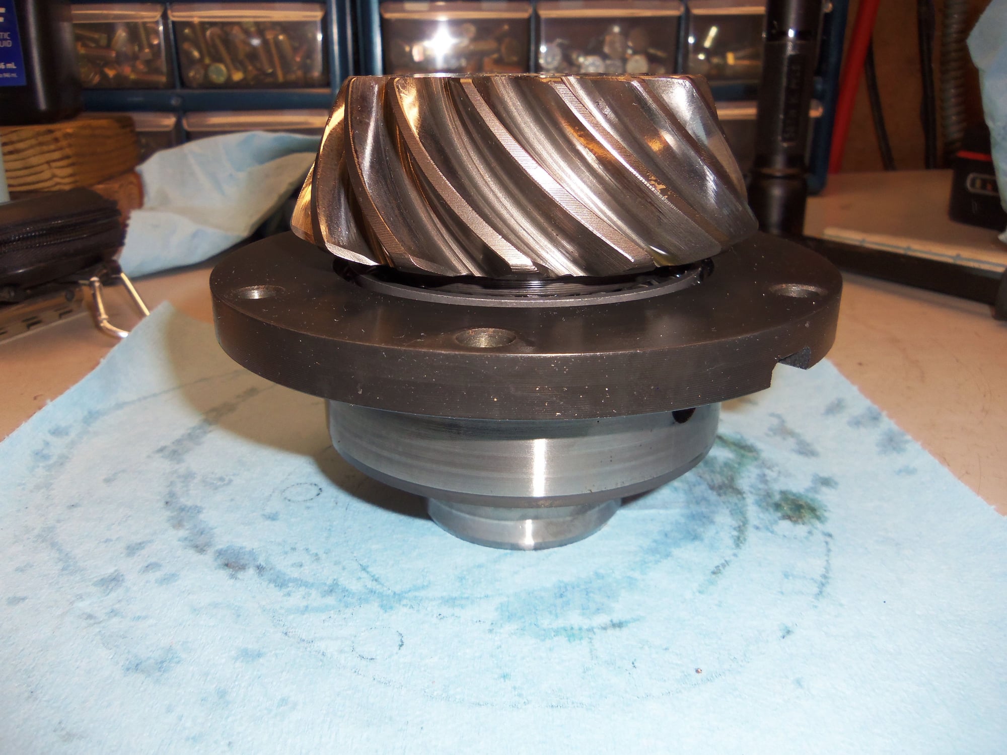
Side of pinion gear.
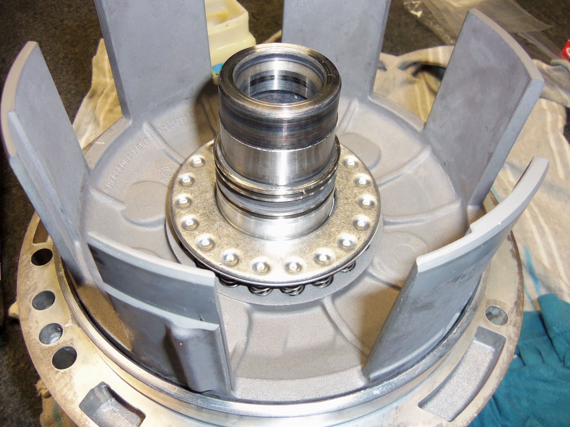
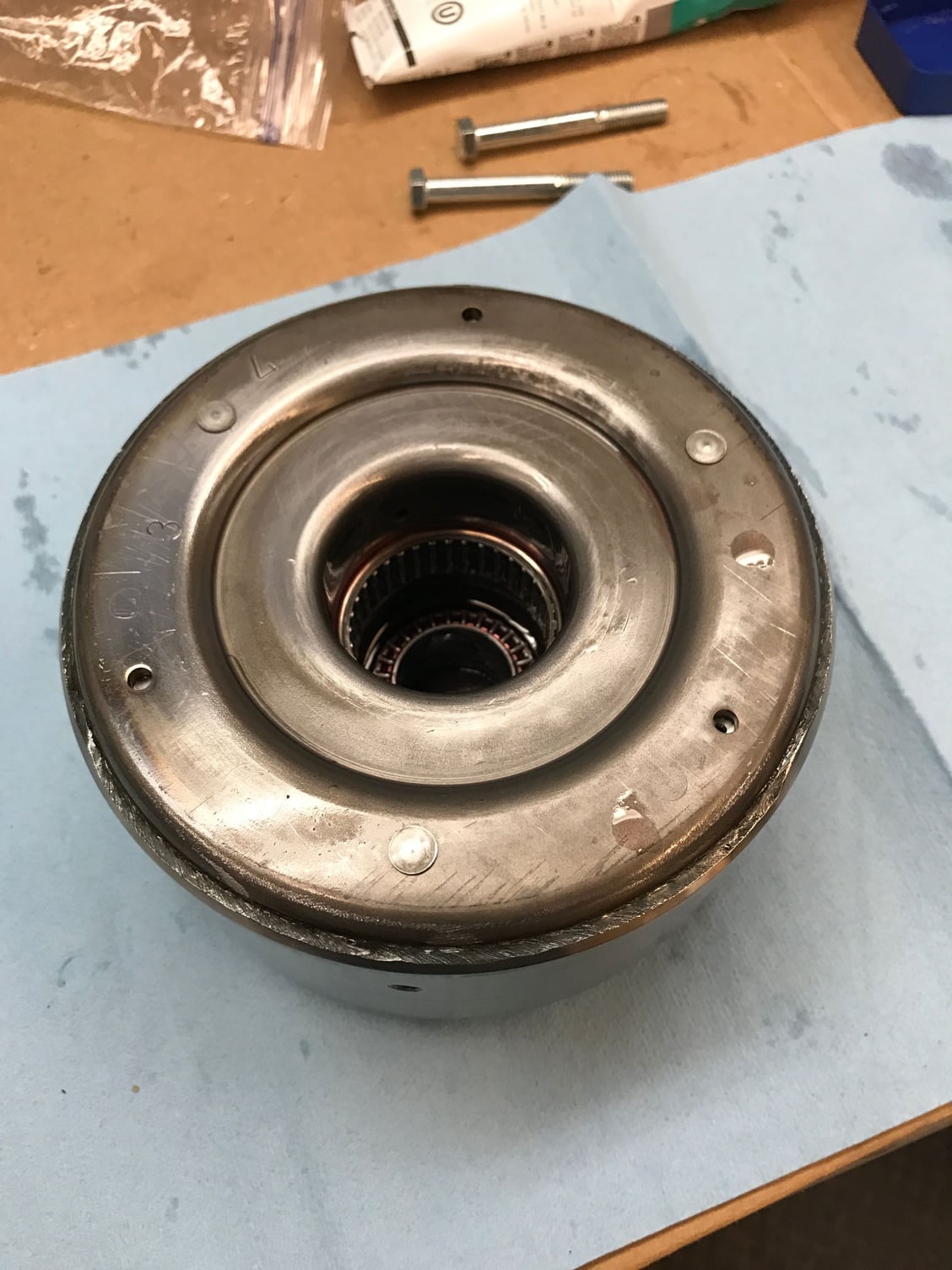
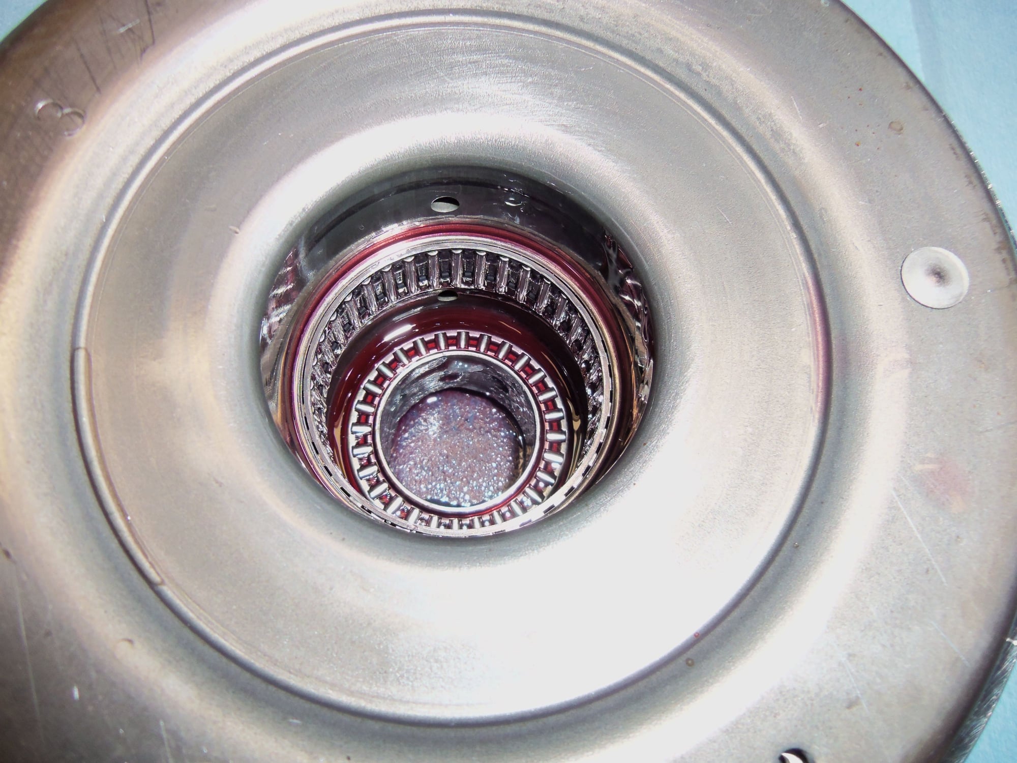
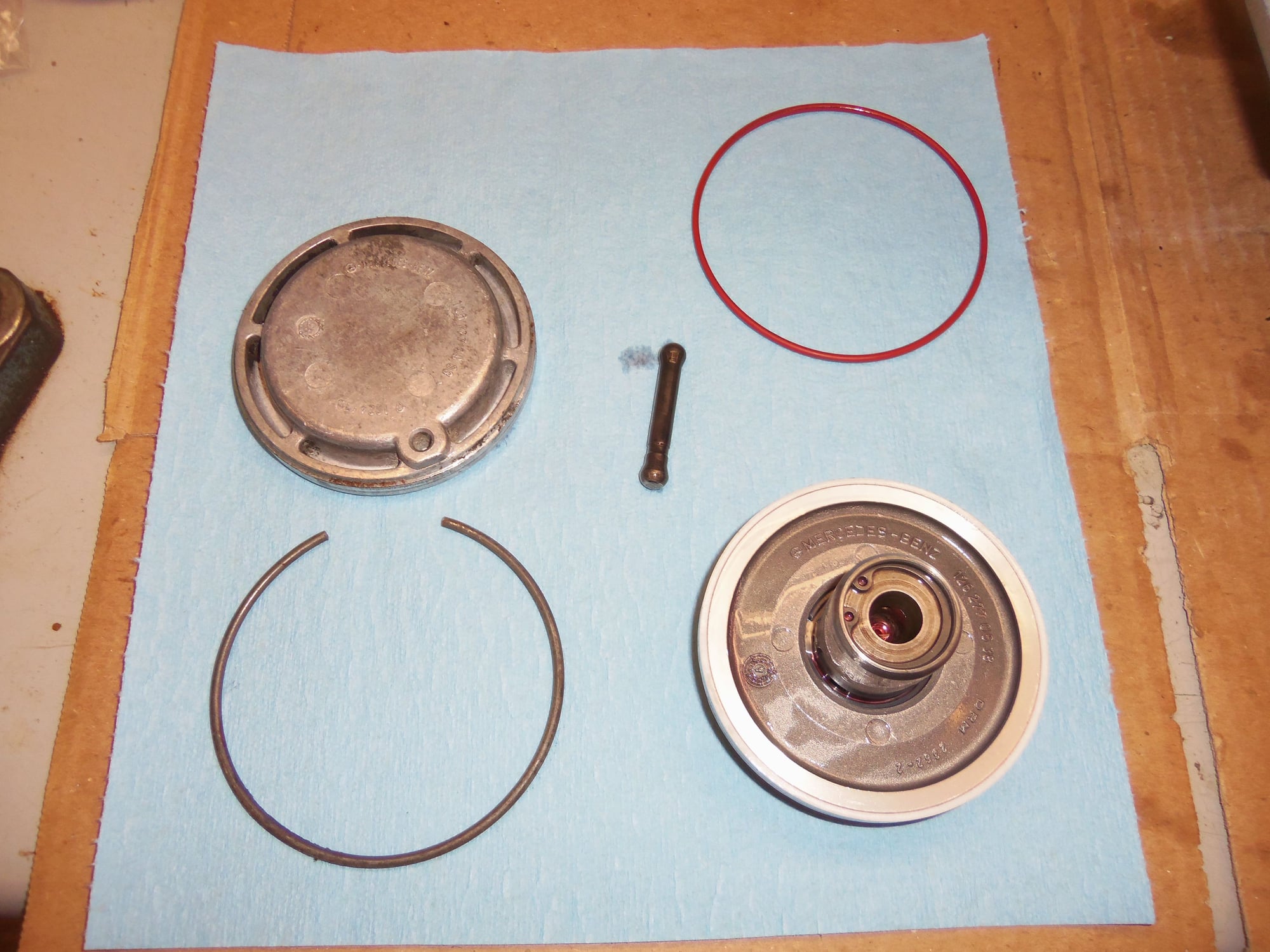
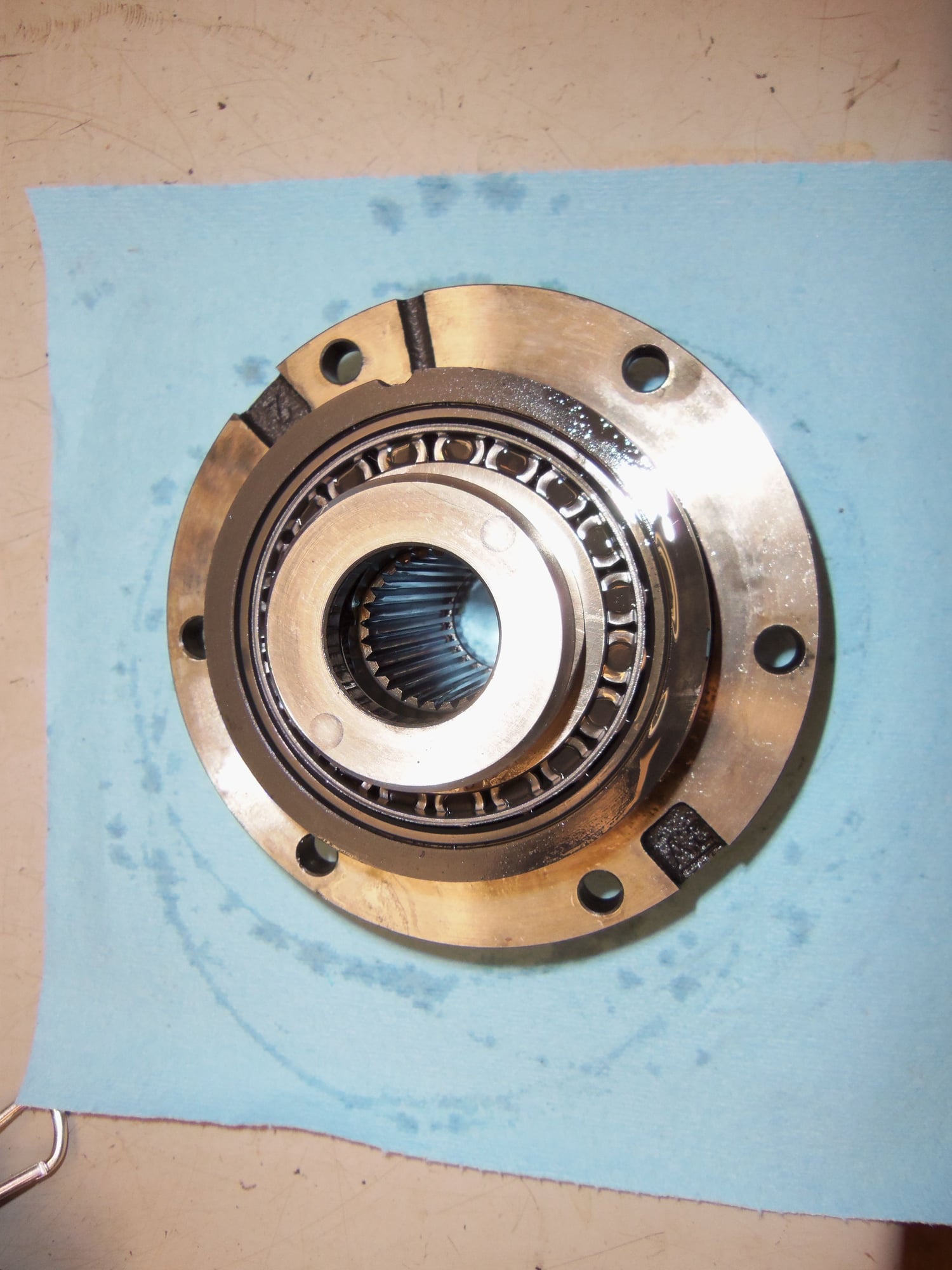
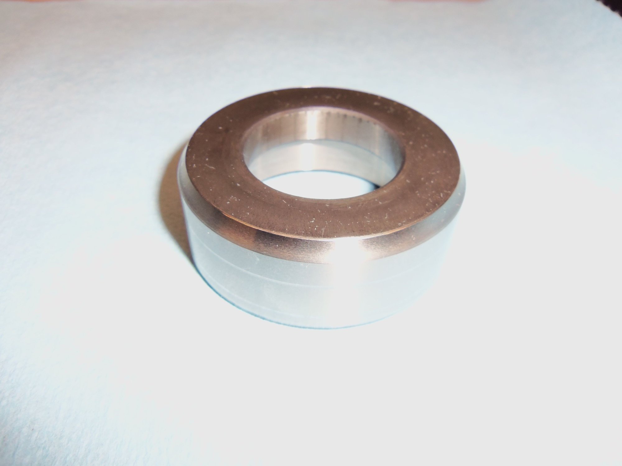
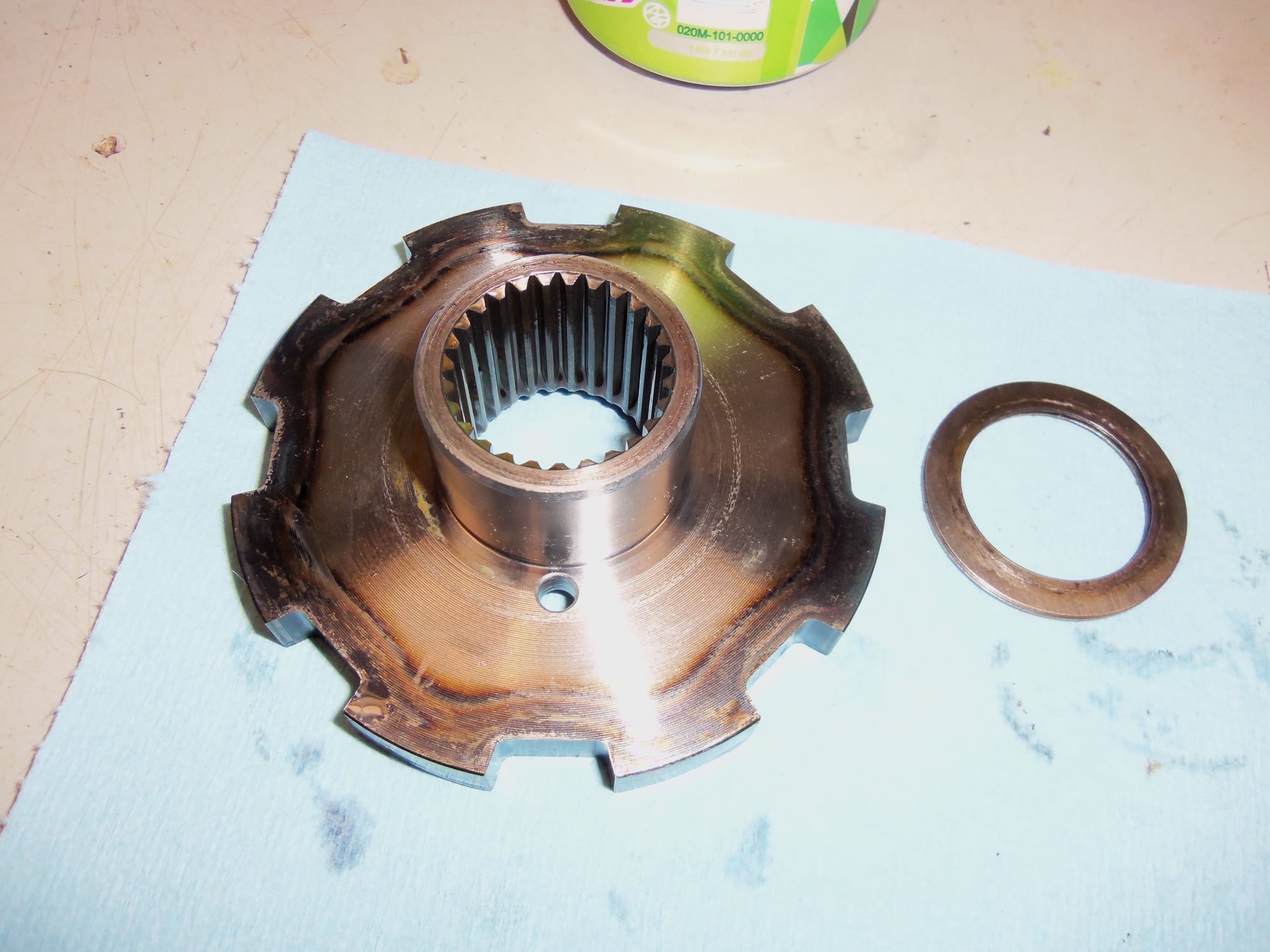
Backside of pinion gear/bearing assembly, showing one of the tapered roller bearings.
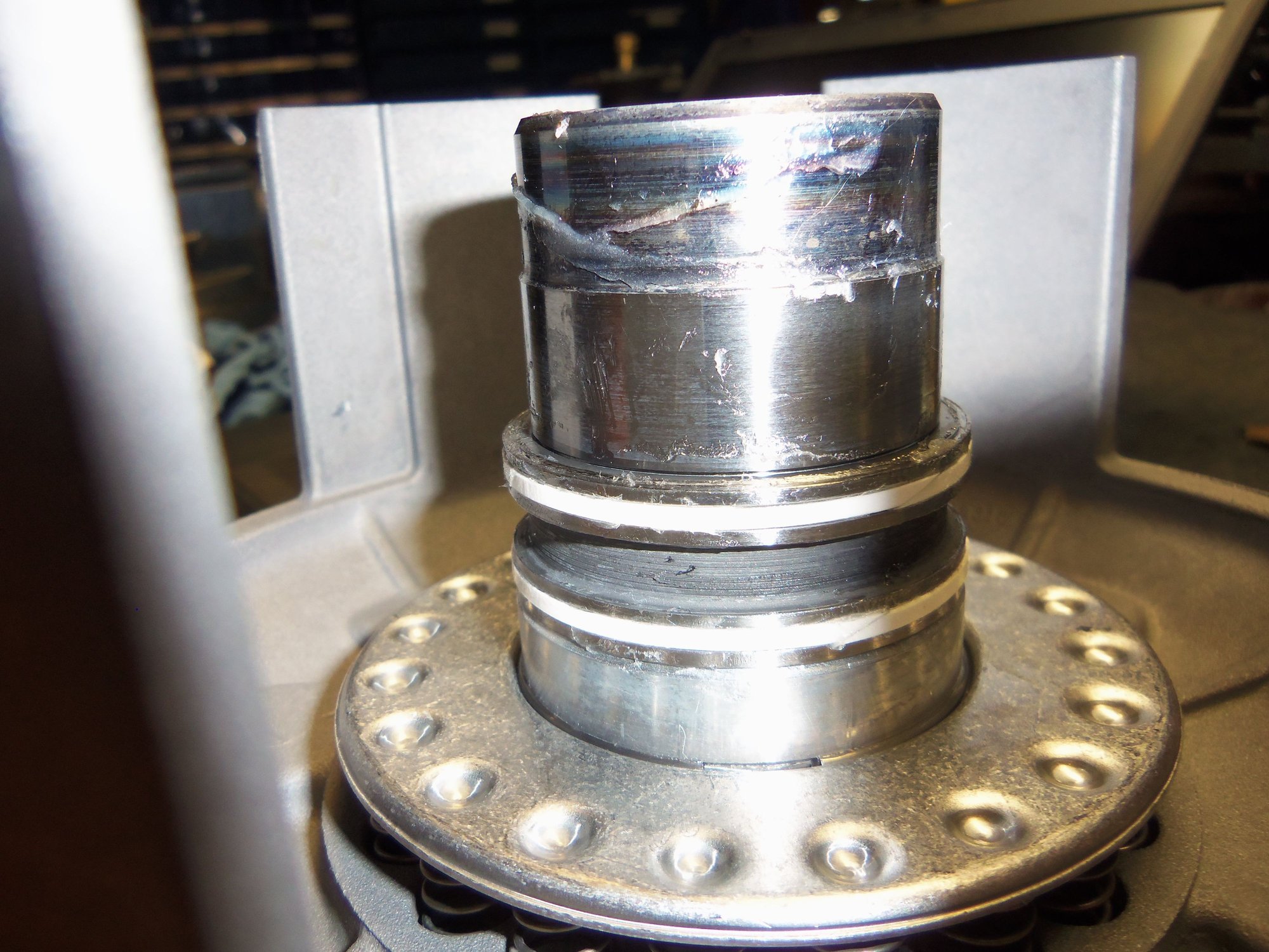
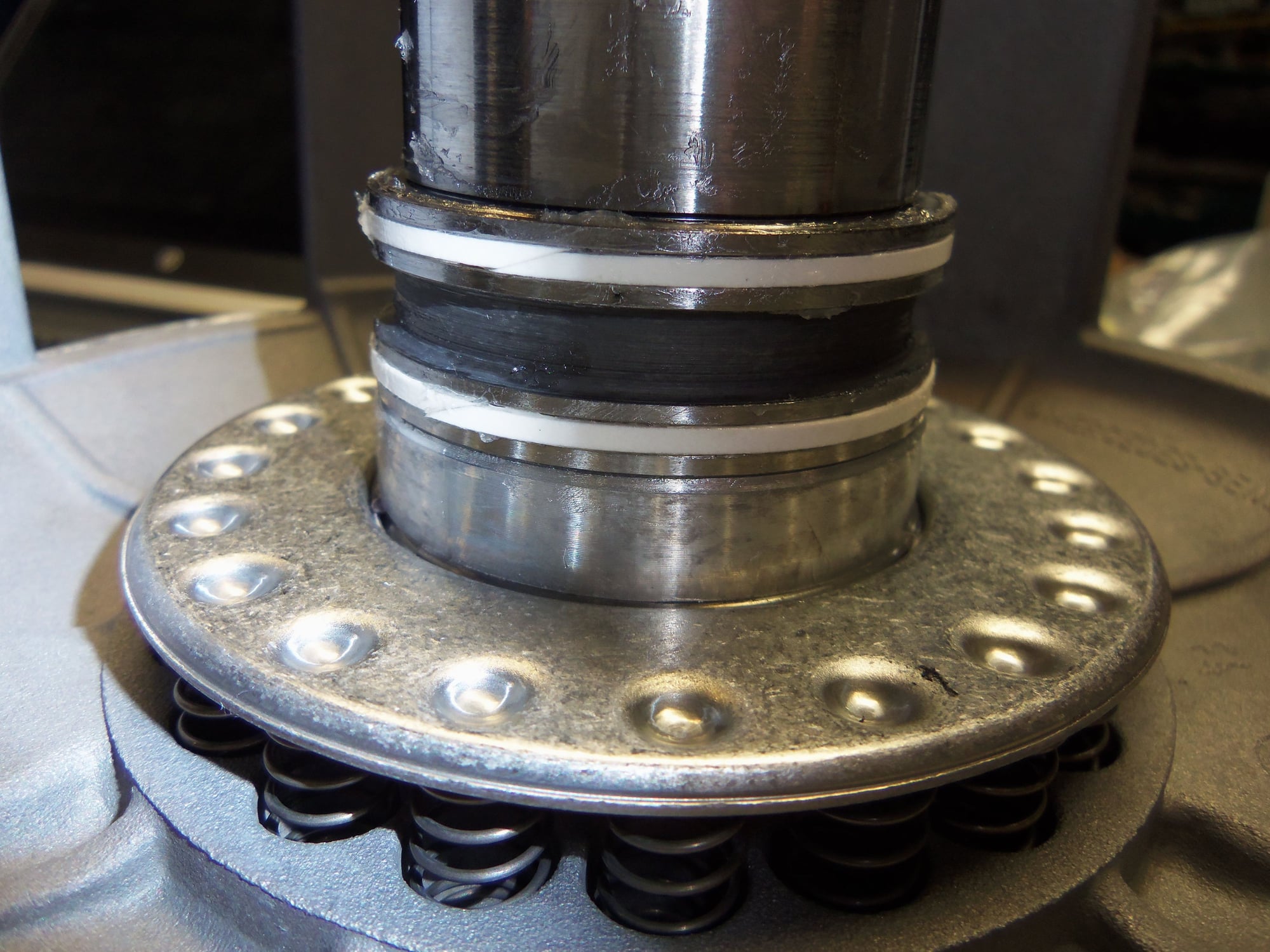
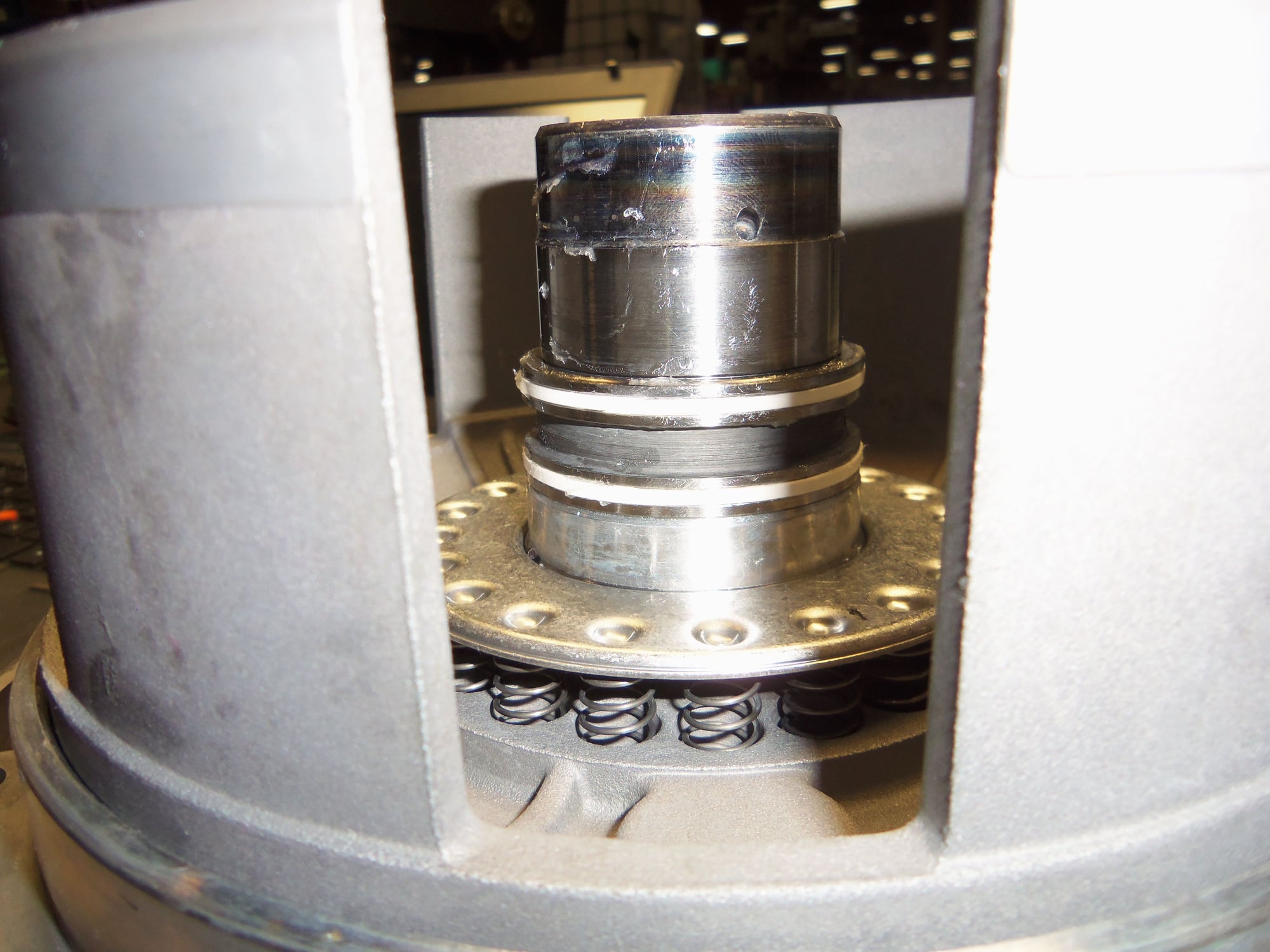
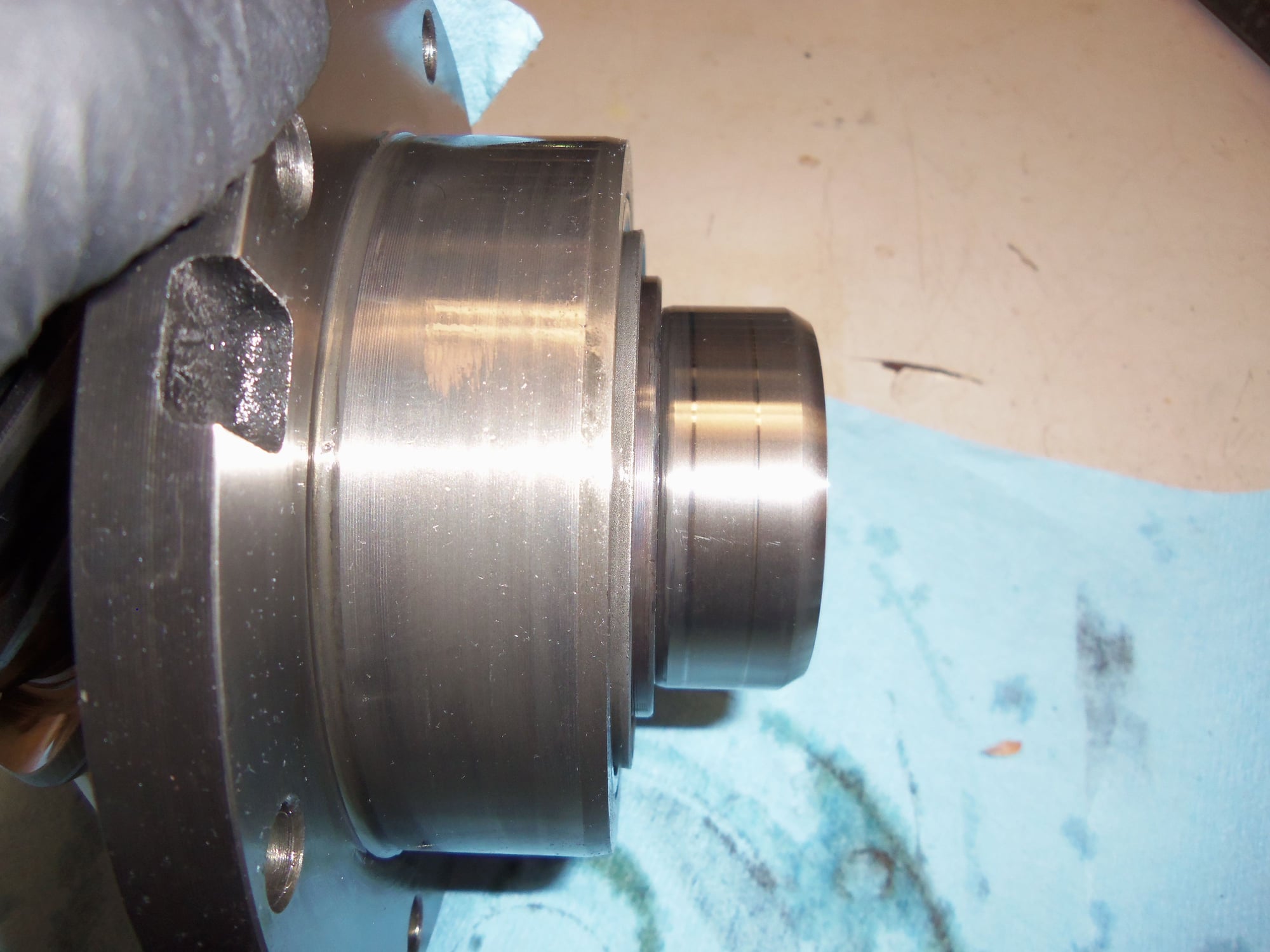
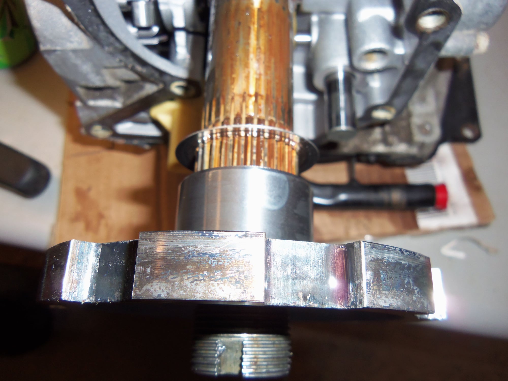
Note this machined 'shaft?' sticking out the back side of the pinion gear/bearing assembly. See the two wear rings. These are from the two radial oil seals in the separator plate.
Closer view of the machined sealing surface.
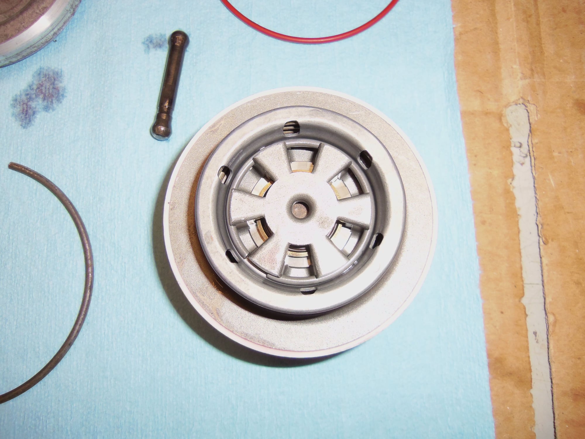
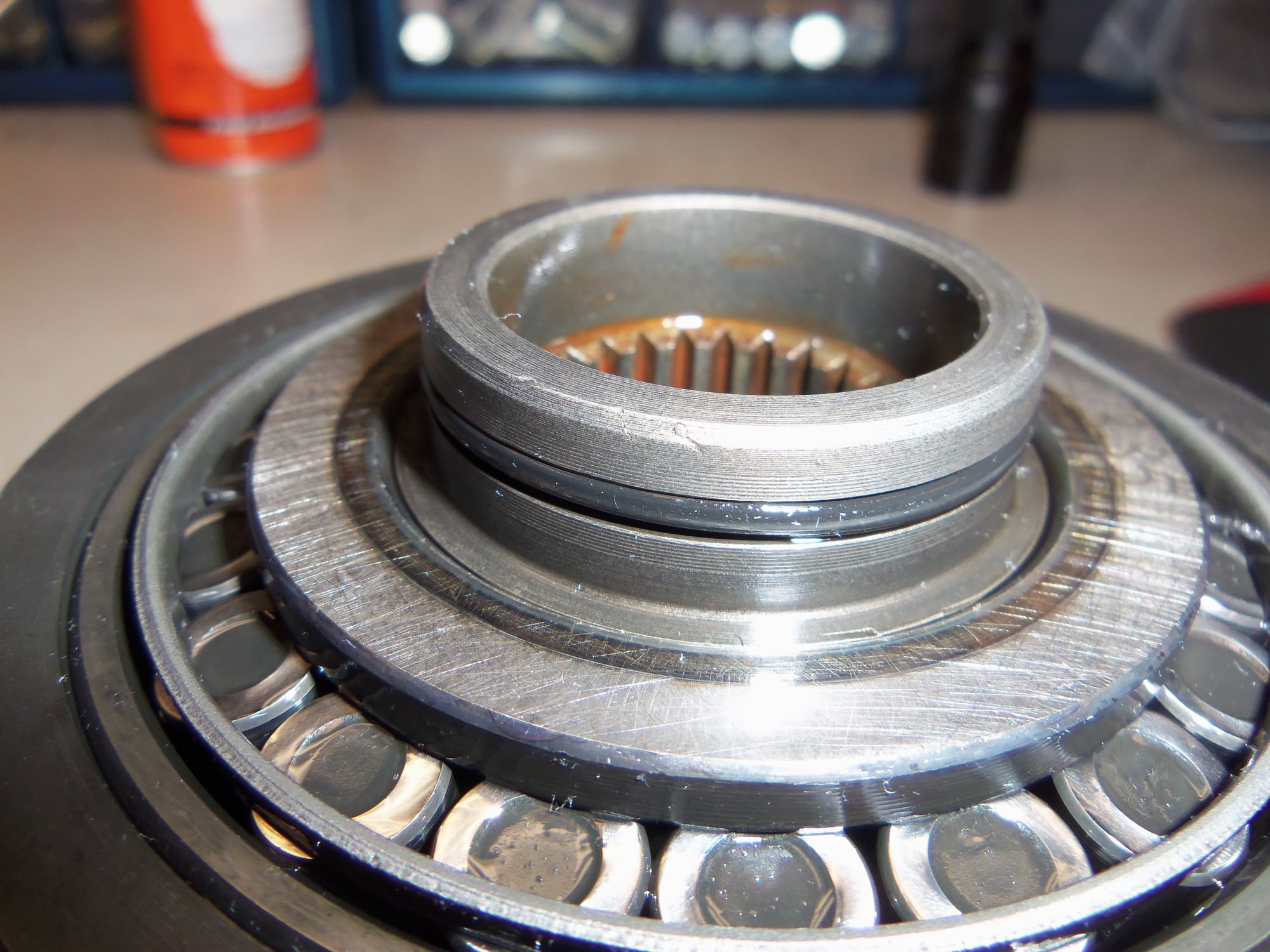
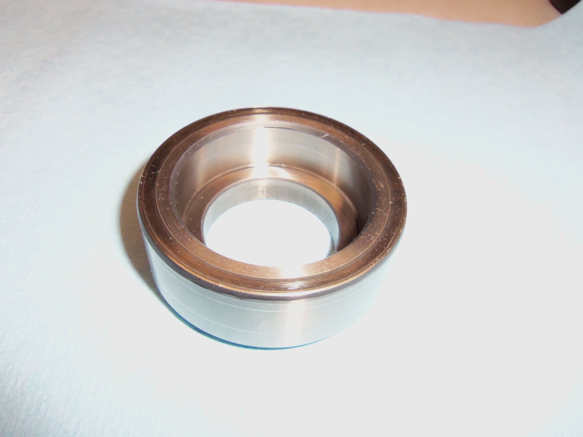
That 'shaft' is actually a cap of sorts, and when removed reveals this O-ring. I am going to assume it is for assembly purposes. The pinion gear 'shaft' OD is such that it will fit the tapered roller bearings. I am going to say they didn't want to use a surface that may be scarred slightly when pushed through a bearing race to be a sealing surface for a radial seal. So, put an O-ring, and a larger diameter cap that will have the sealing surface on its OD. At least this sounds good in my head...
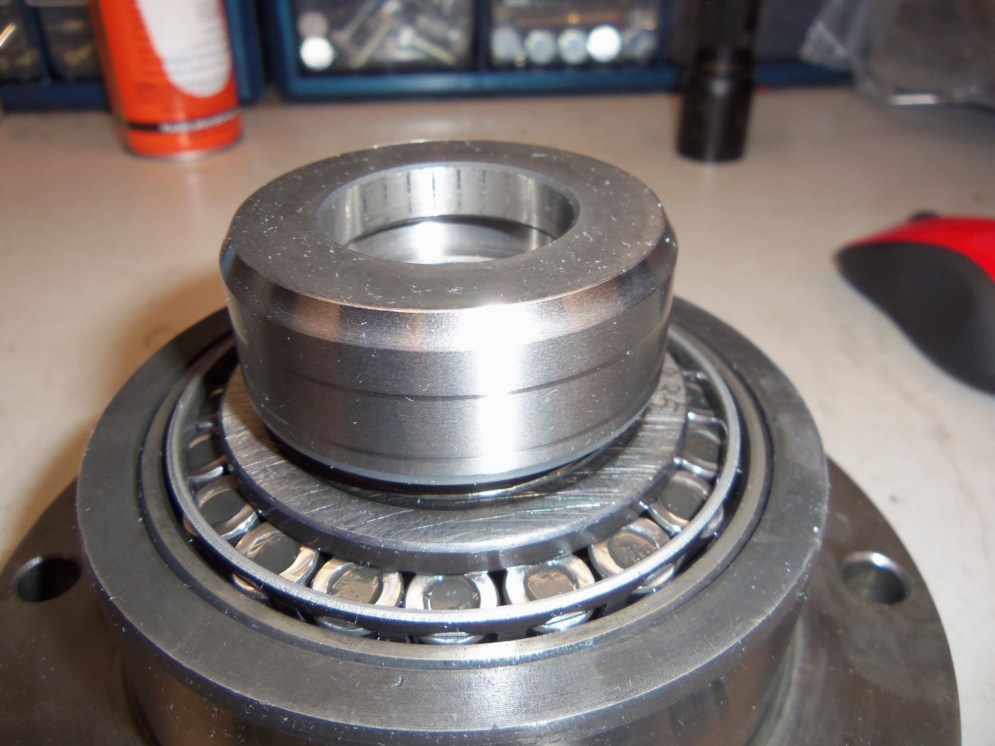
Top side of sealing cap. Edge is tapered to smoothly go through radial seals.
Underside of cap, showing machined inner surface for sealing the O-ring.
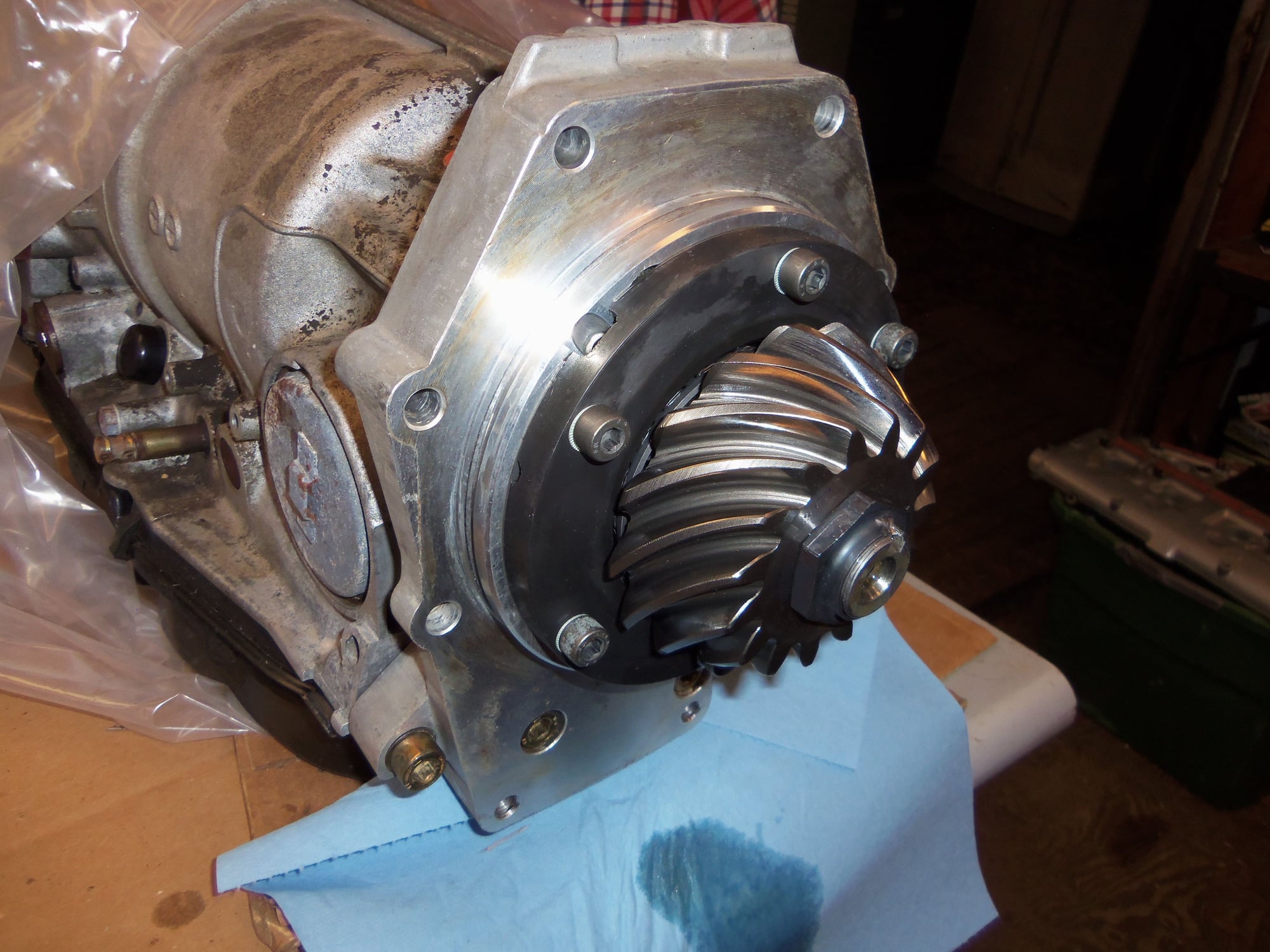
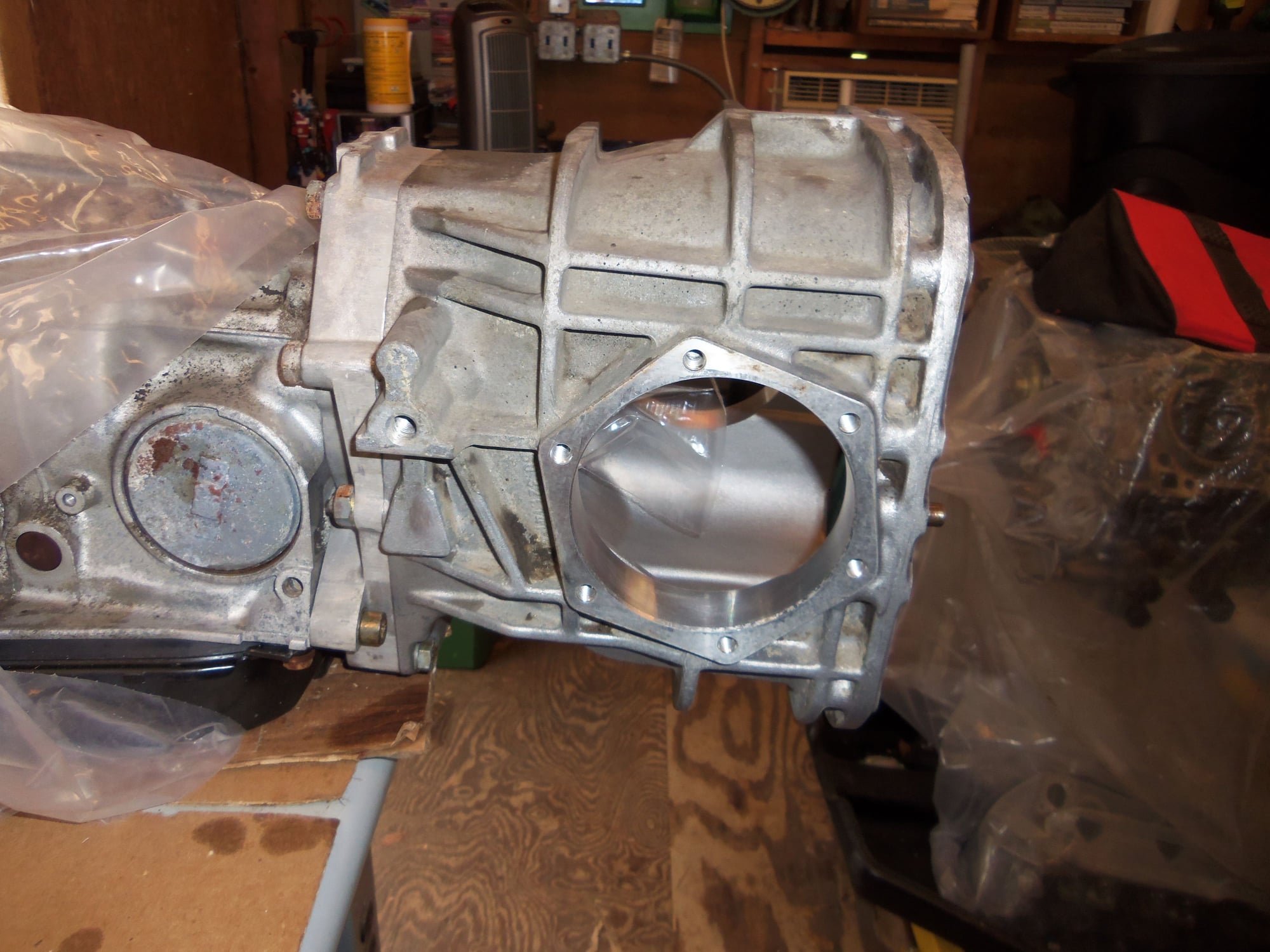
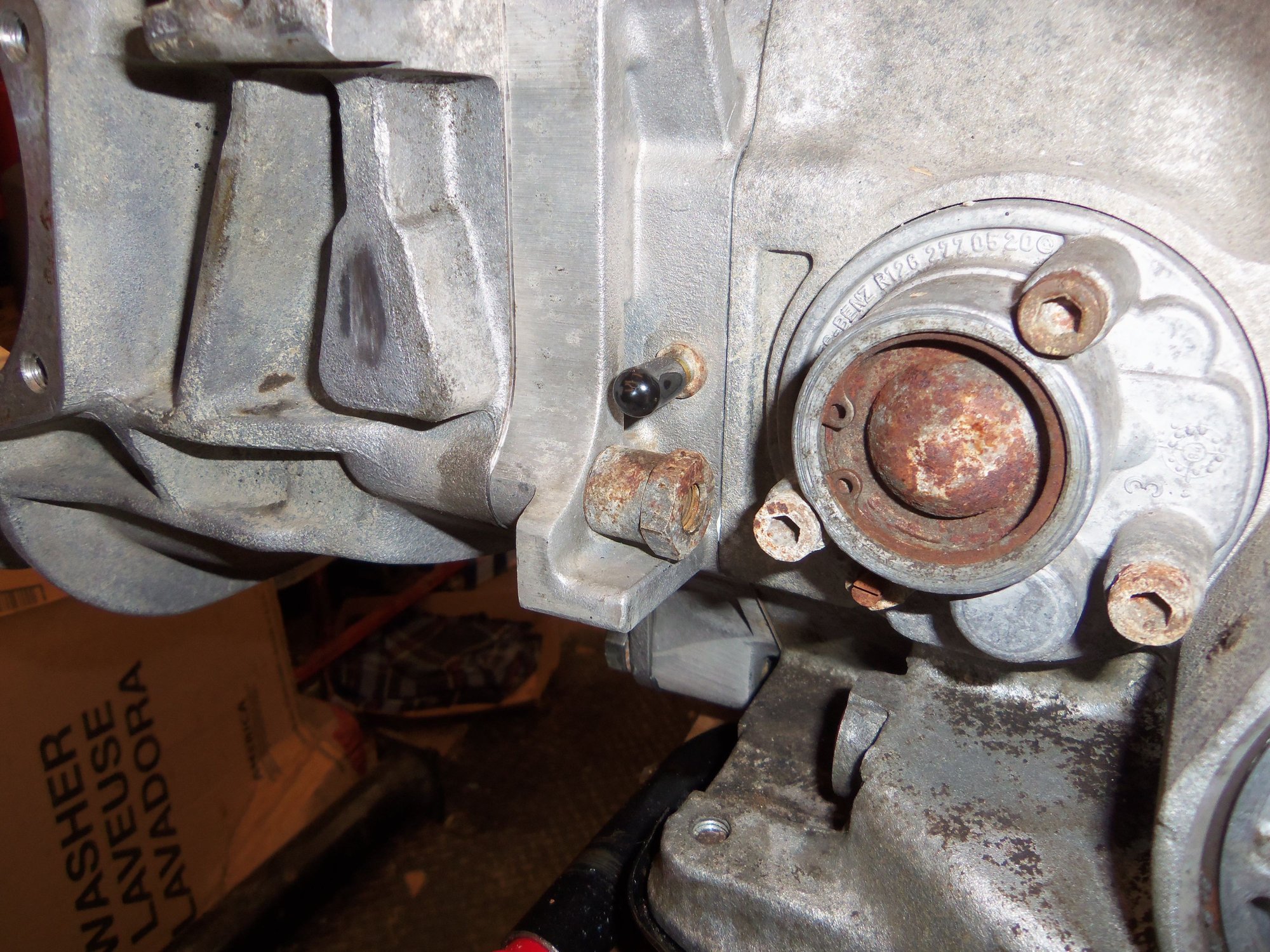
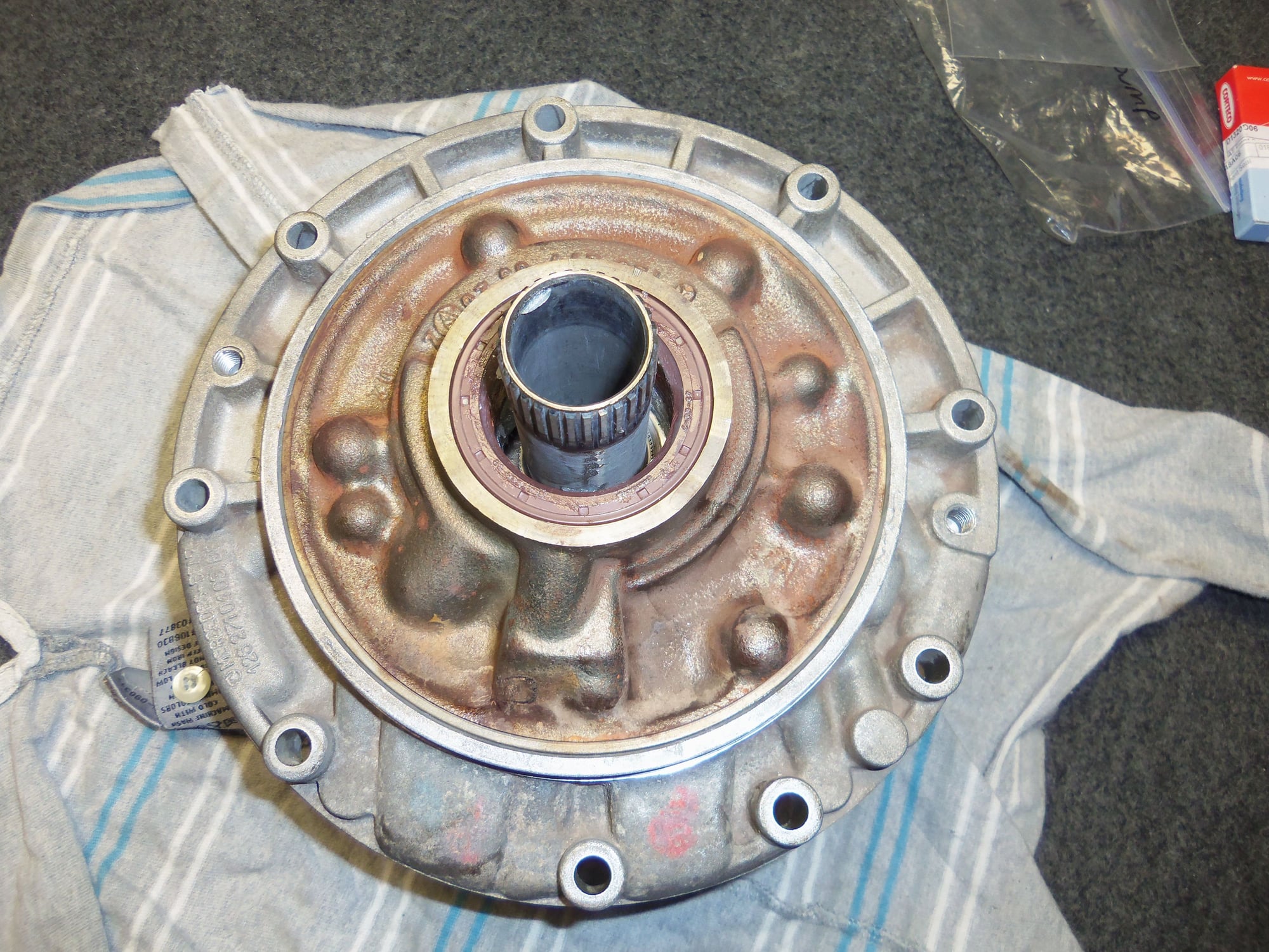
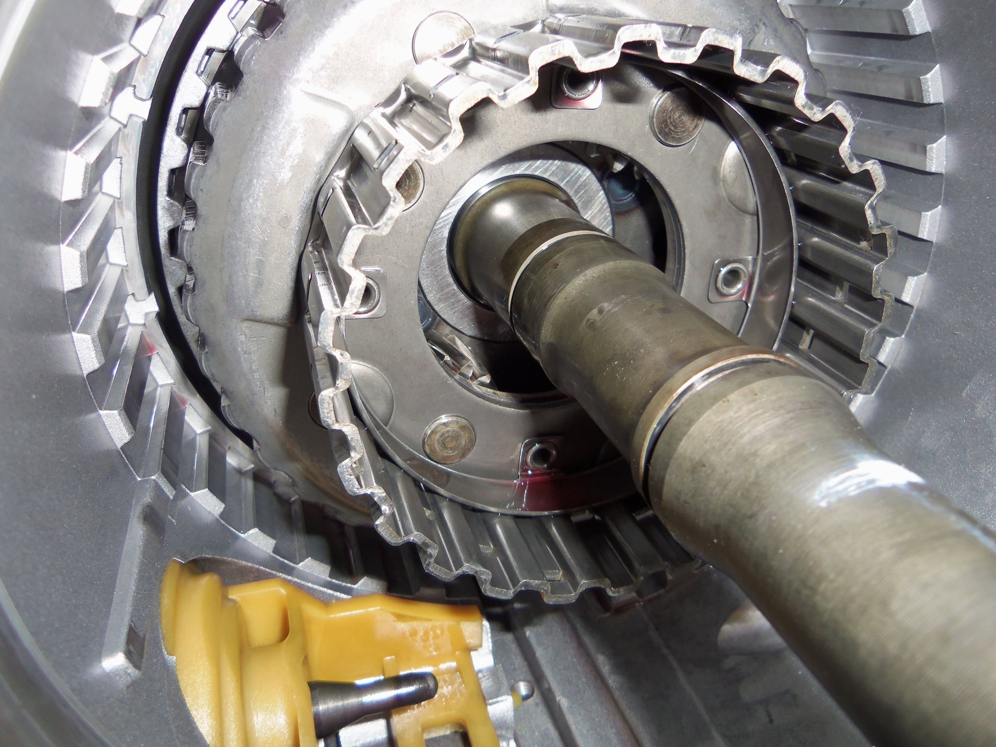
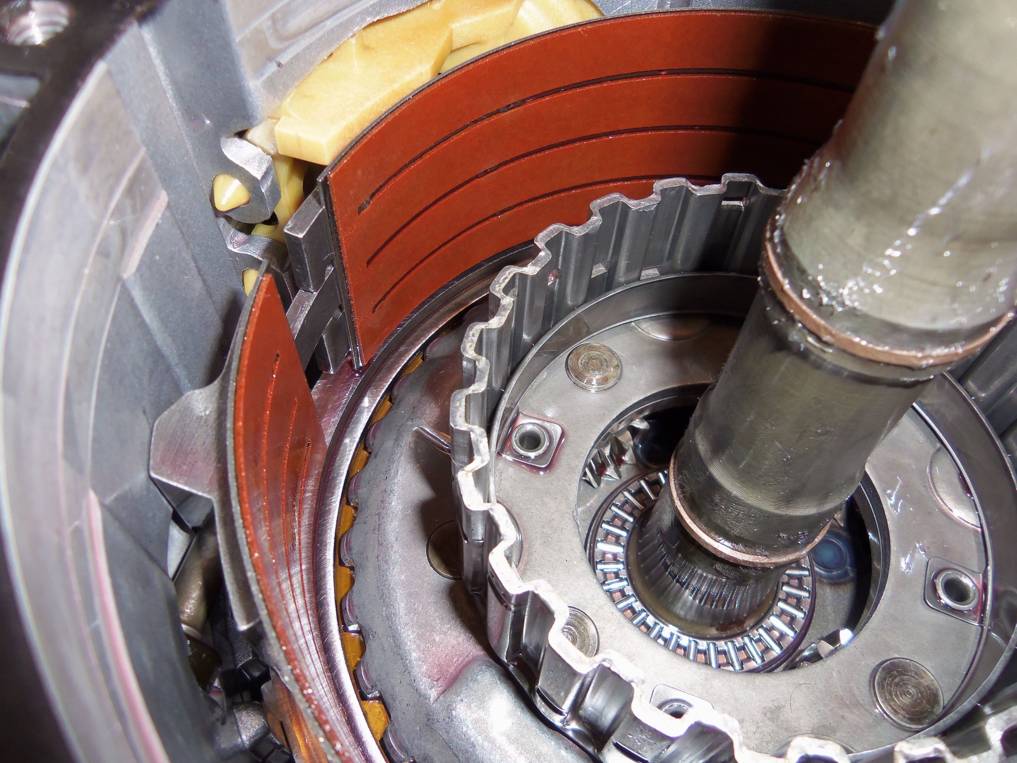
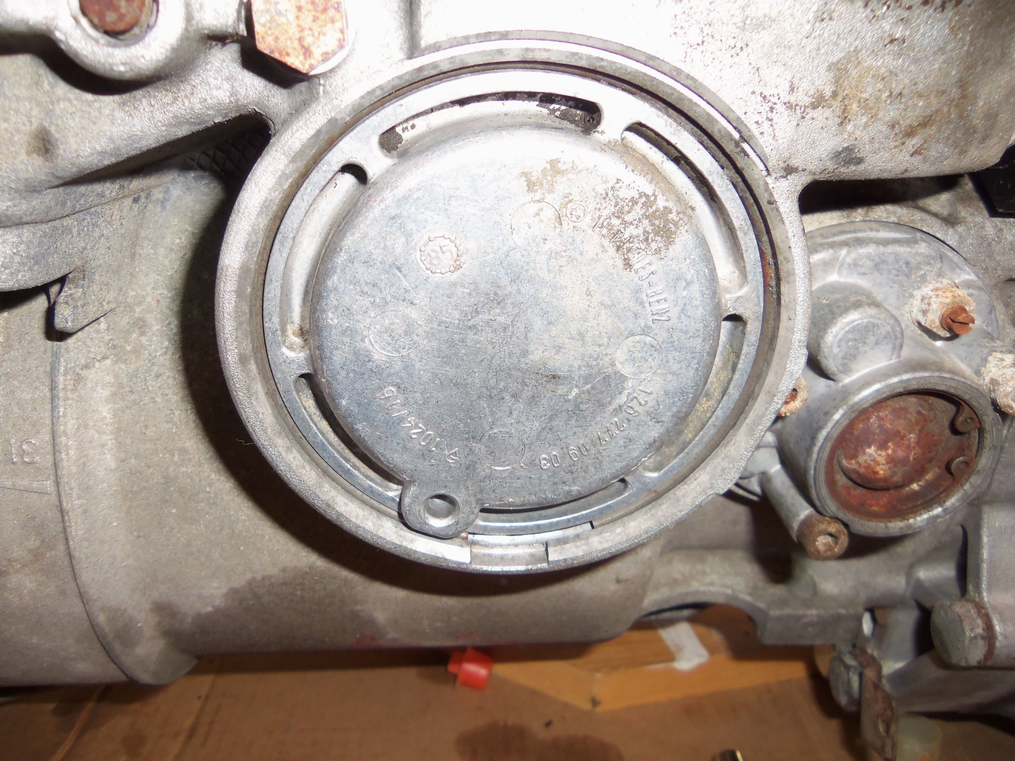
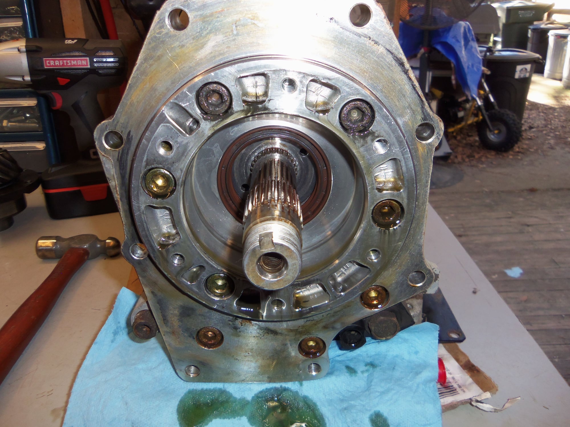
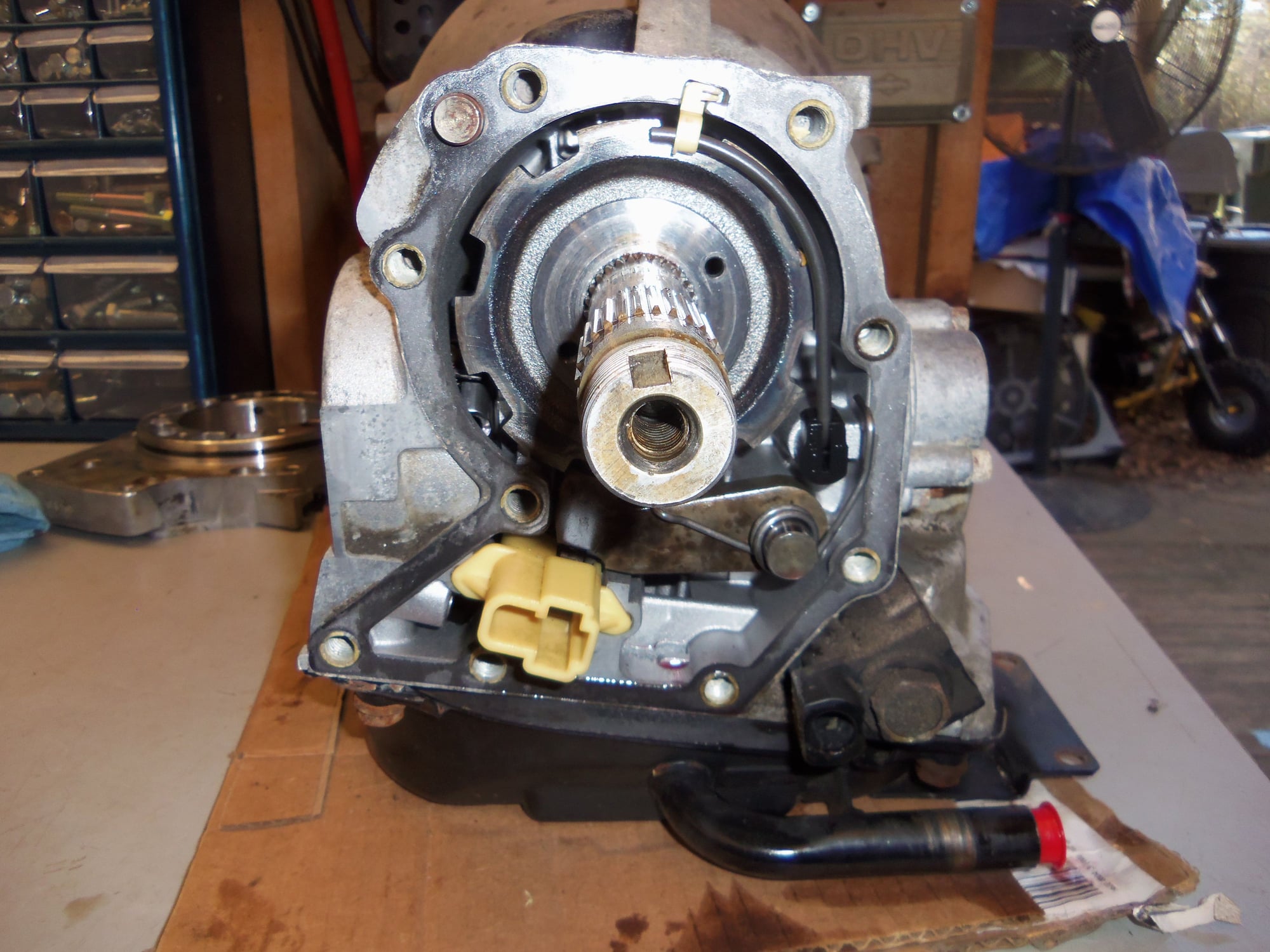
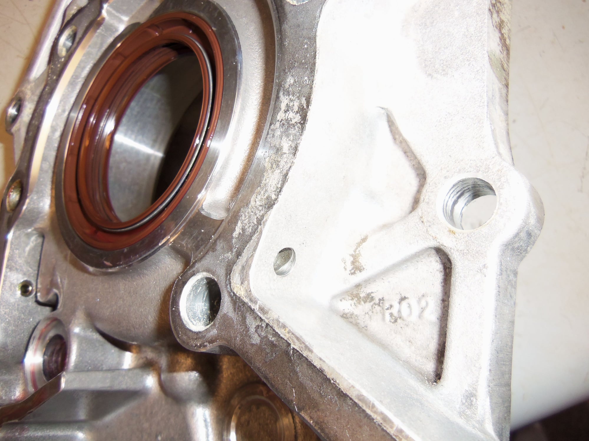
With the pinion gear/bearing assembly out of the way, I could see the offending radial seal that was seeping gear oil from the differential. It is quite possible to replace this seal, and the identical one just behind it, with the separator plate in place. I chose to fully remove the separator plate for cleaning and to replace the gasket behind it.
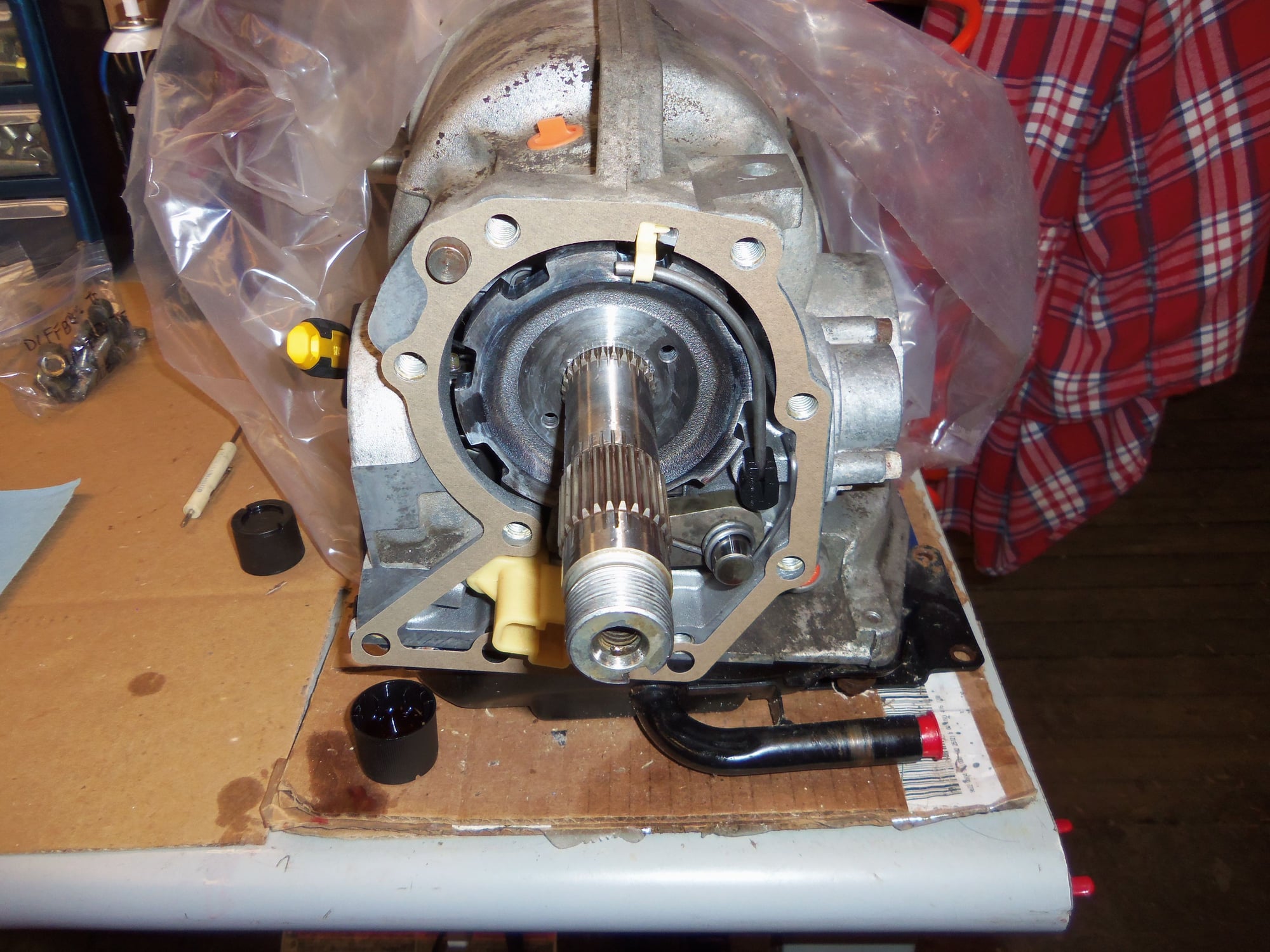
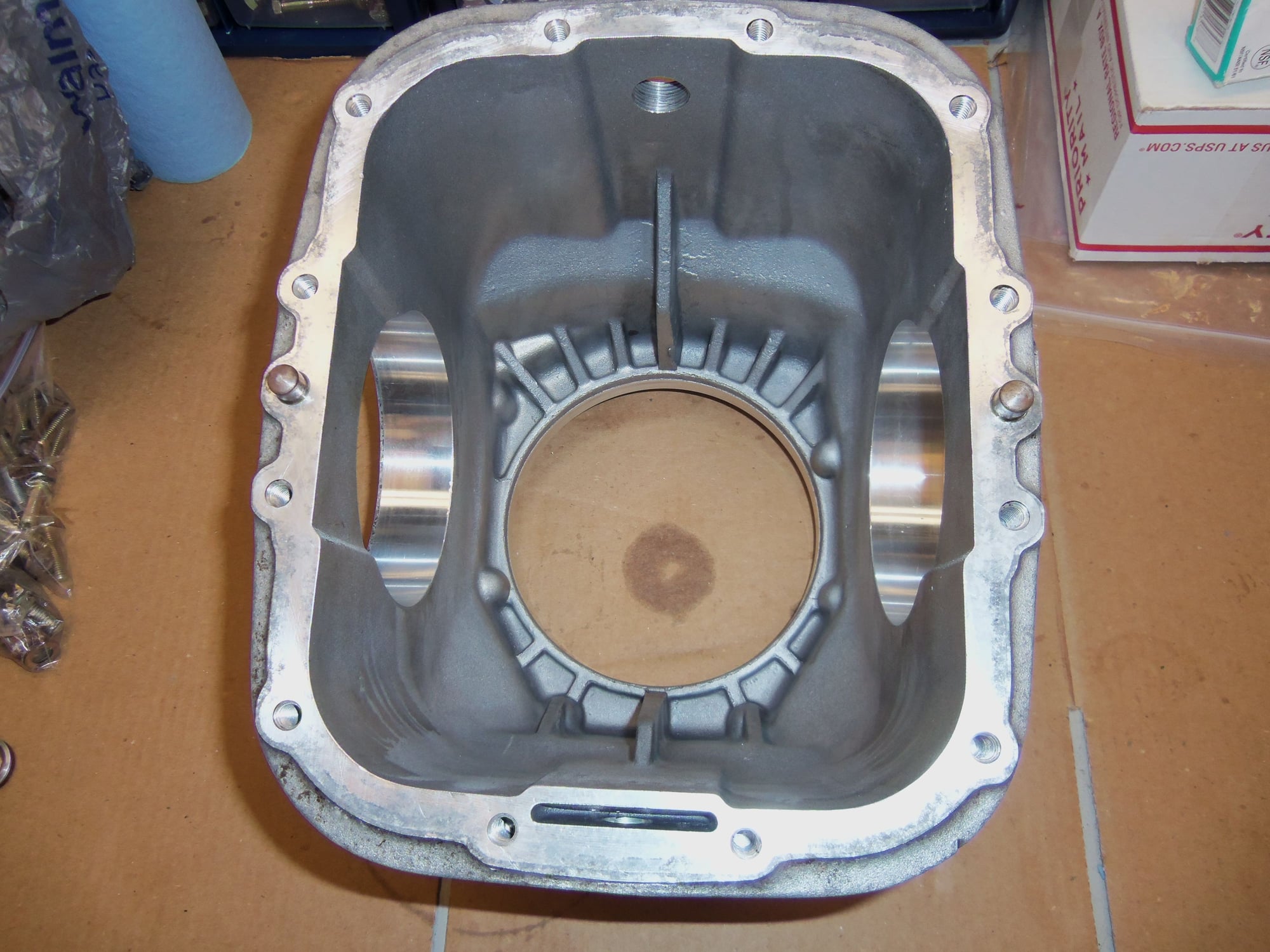
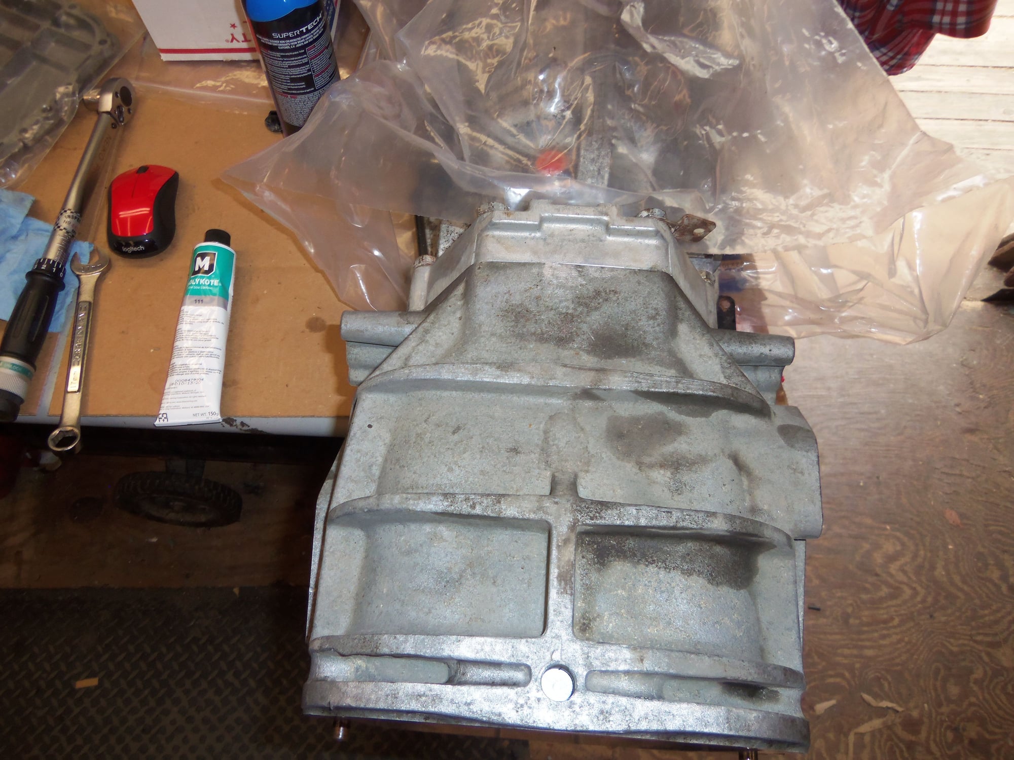
After removing this plate, I was well and truly into the guts of the back of the transmission.
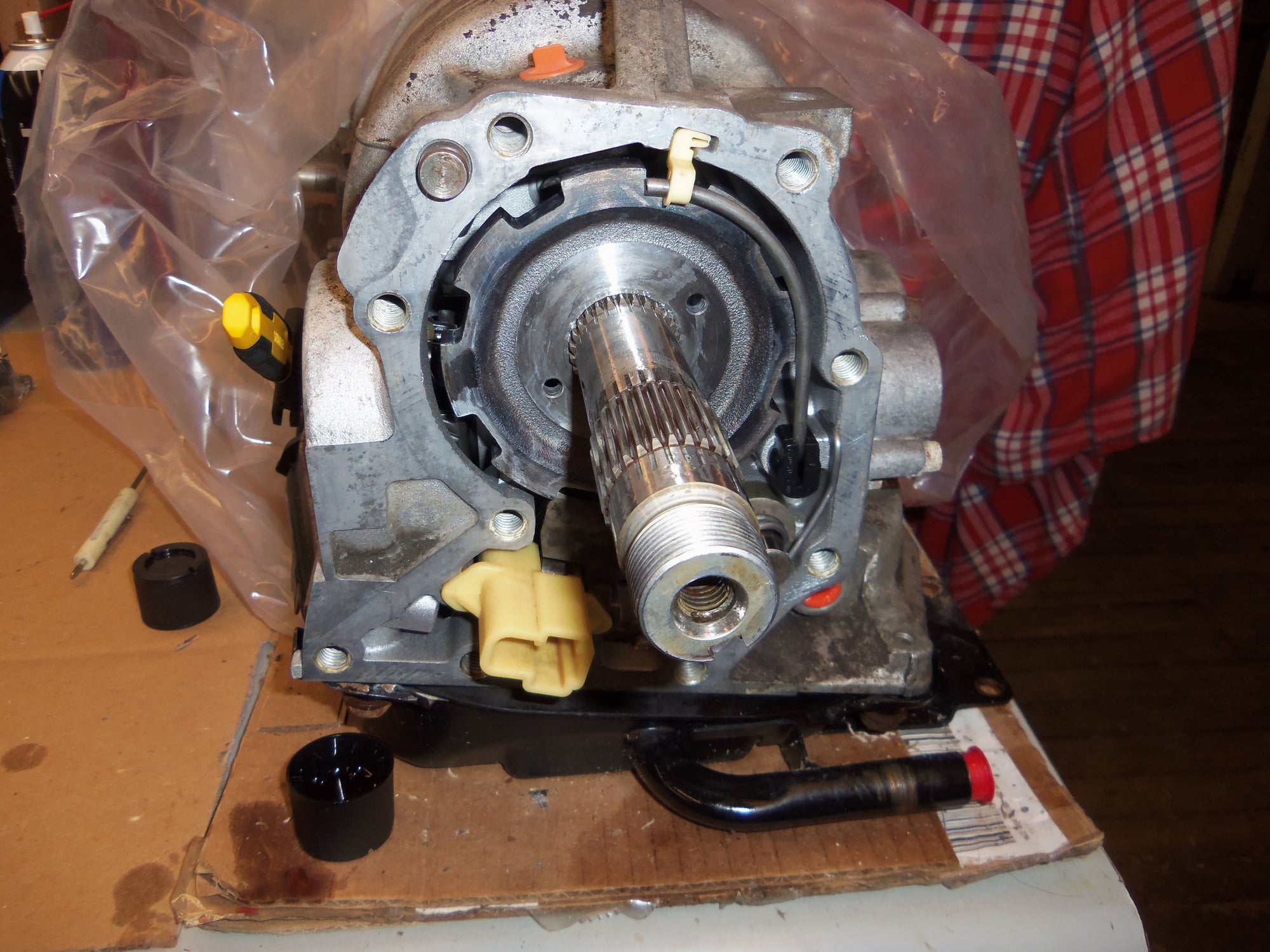
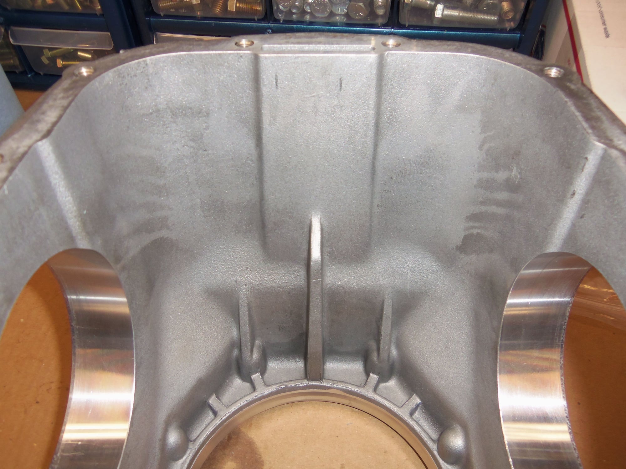
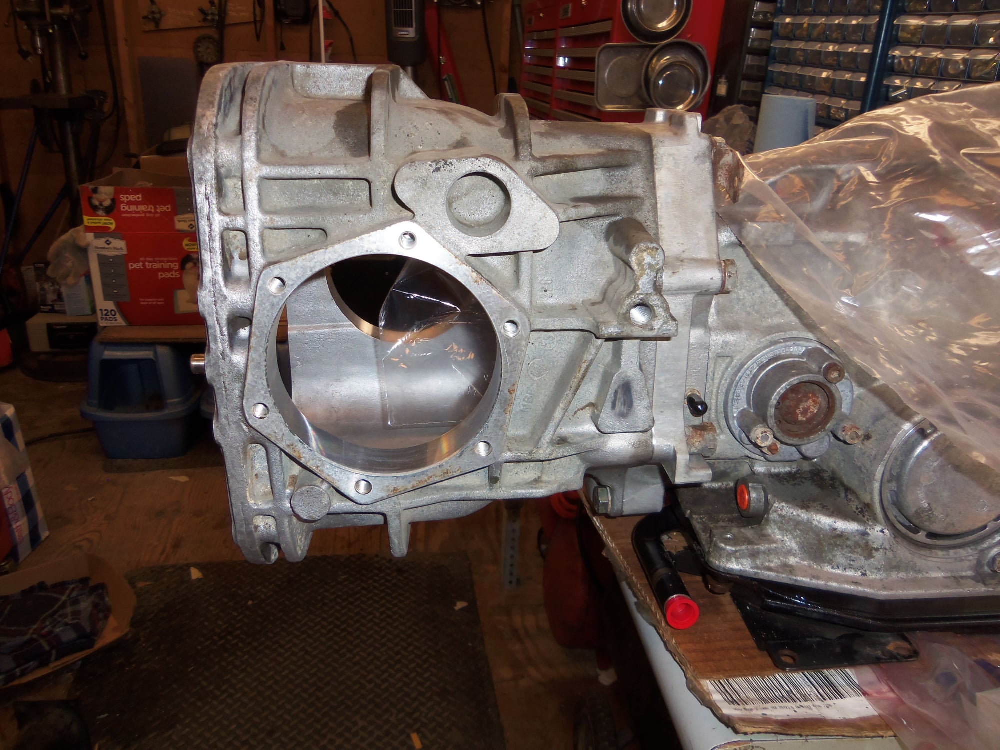
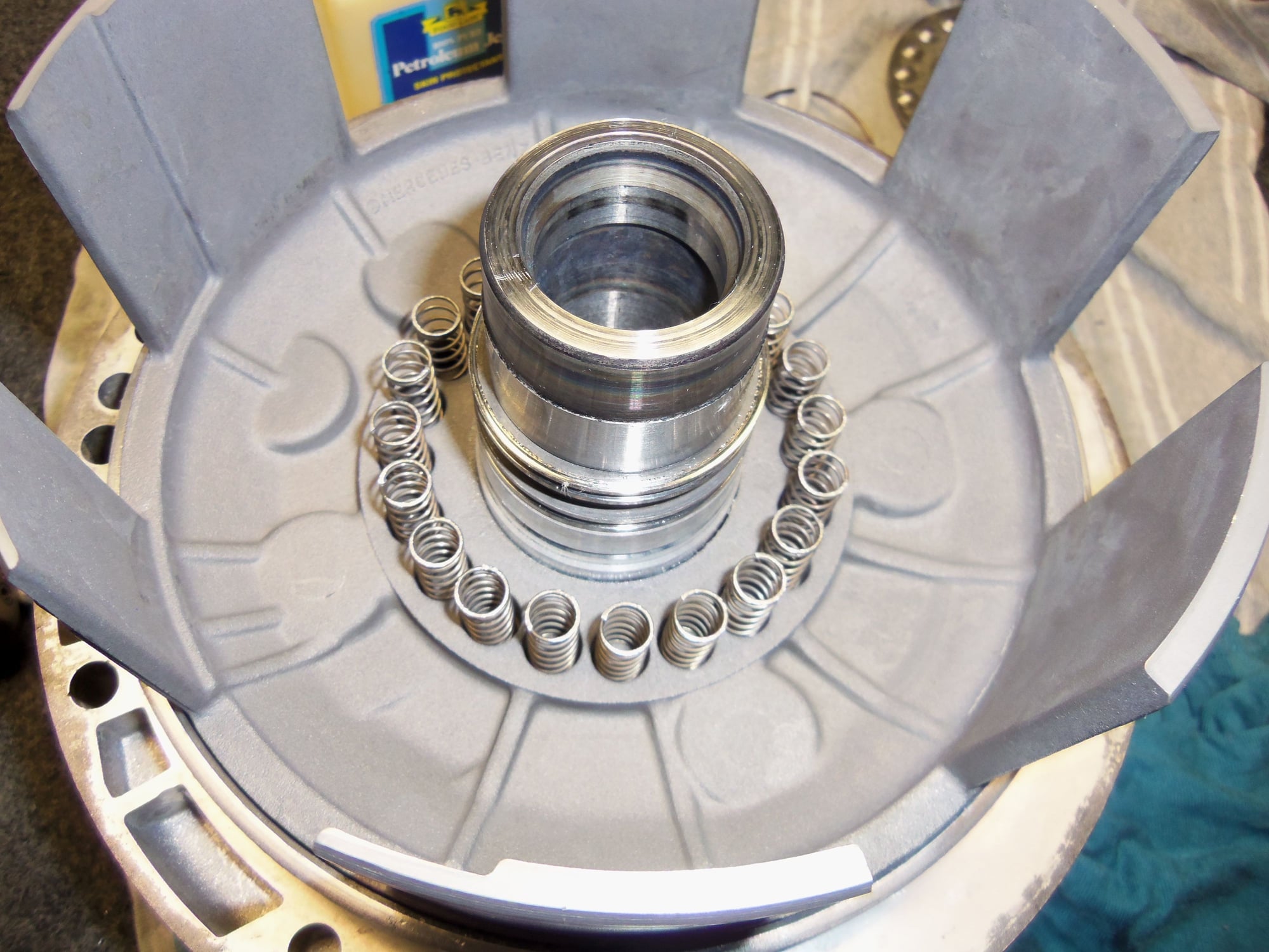
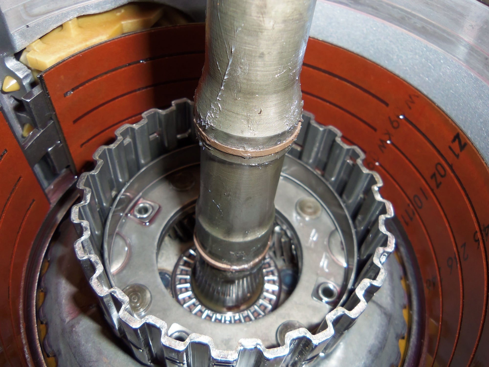
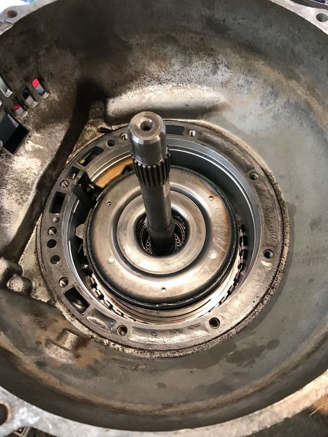
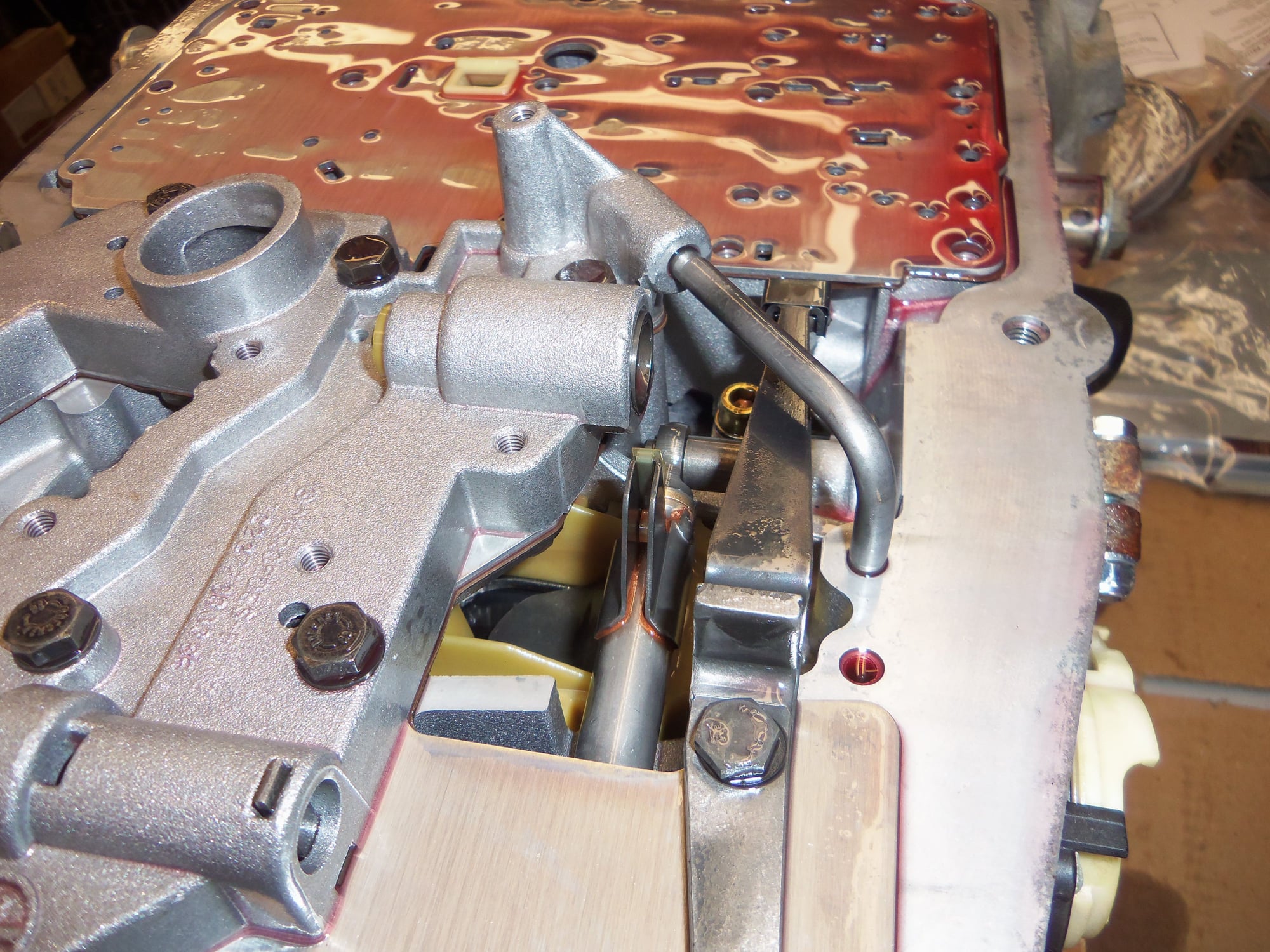
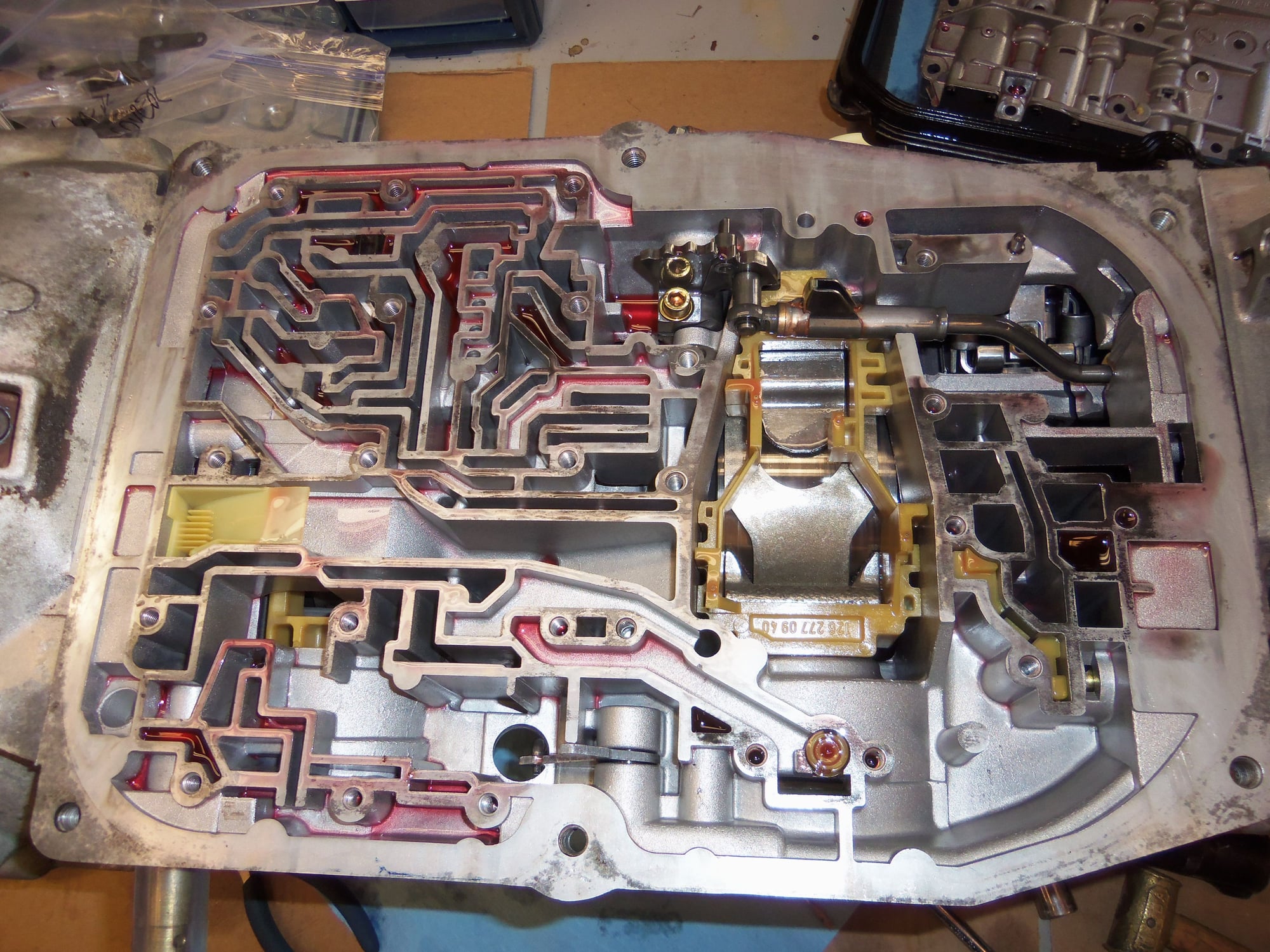
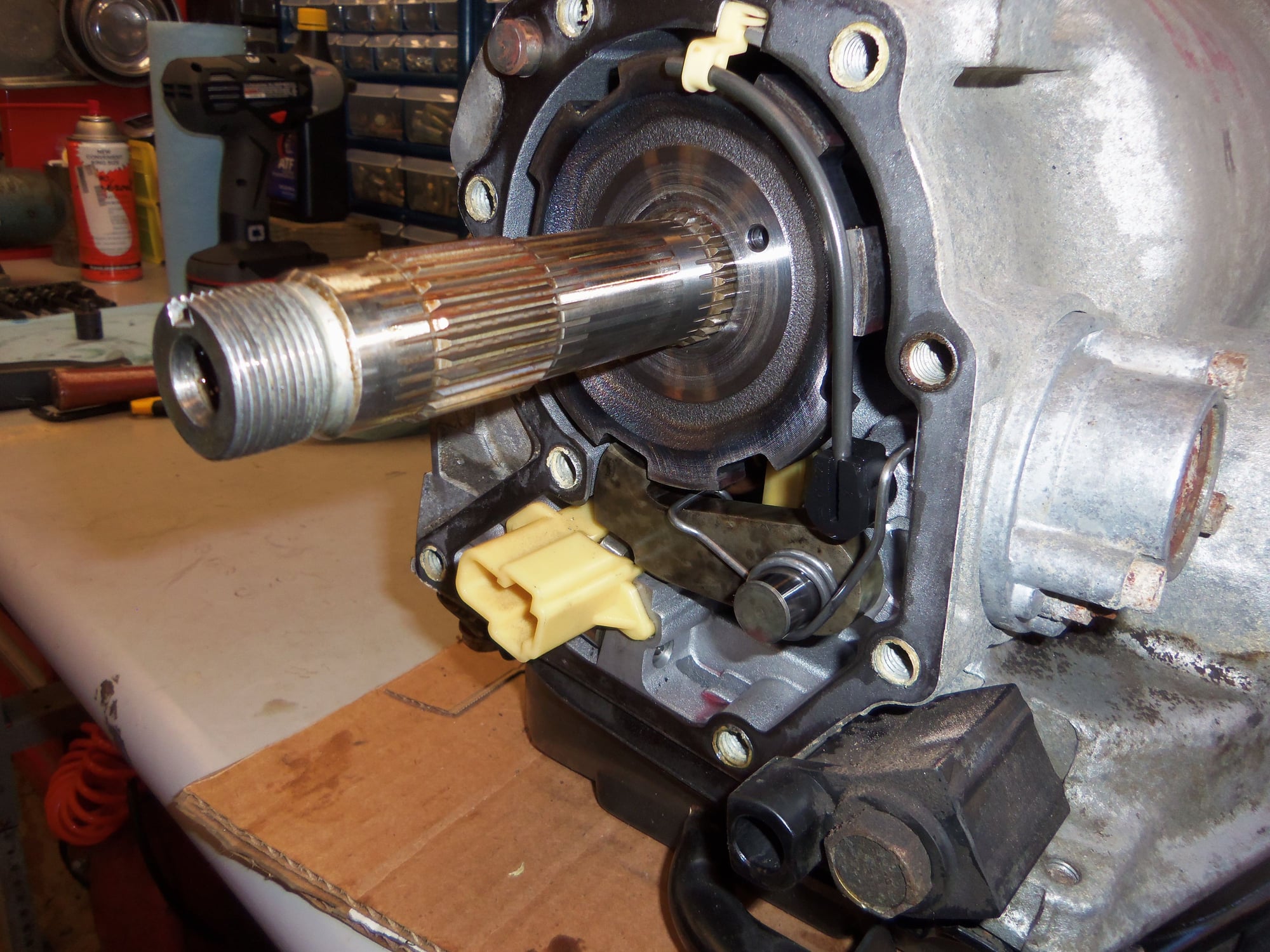
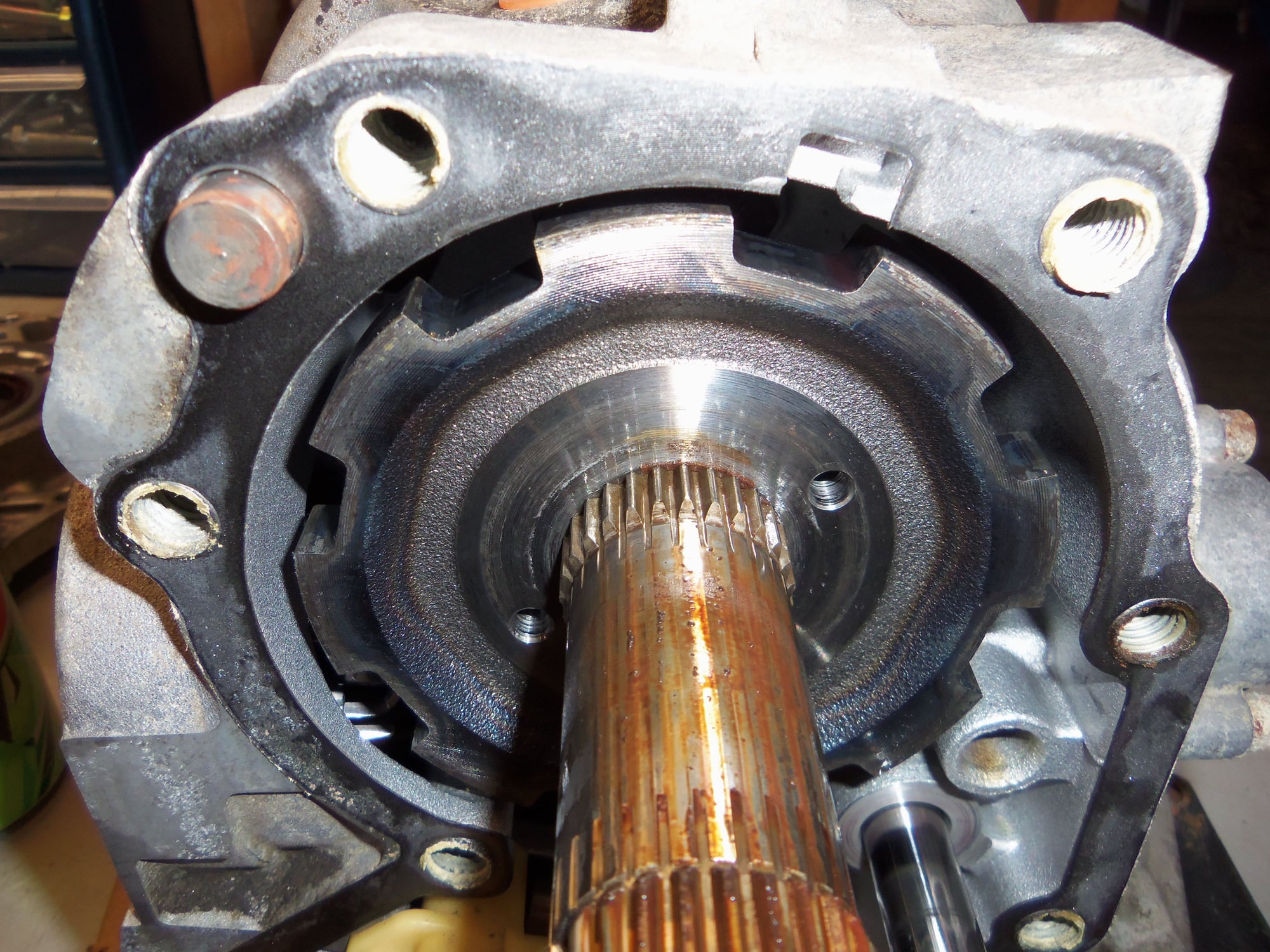
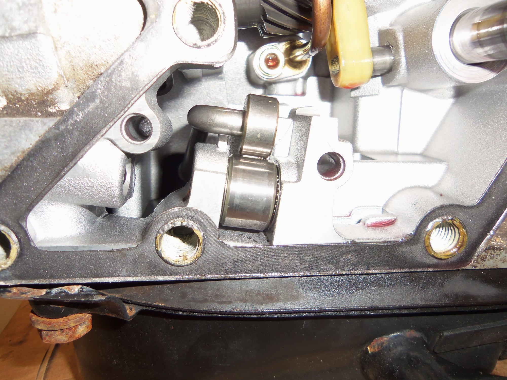
Guts of back of the transmission exposed by the removal of the separator plate.
Output shaft of the transmission.
Look close, you can see an oil feed tube at the right side with a plastic retainer at the top.
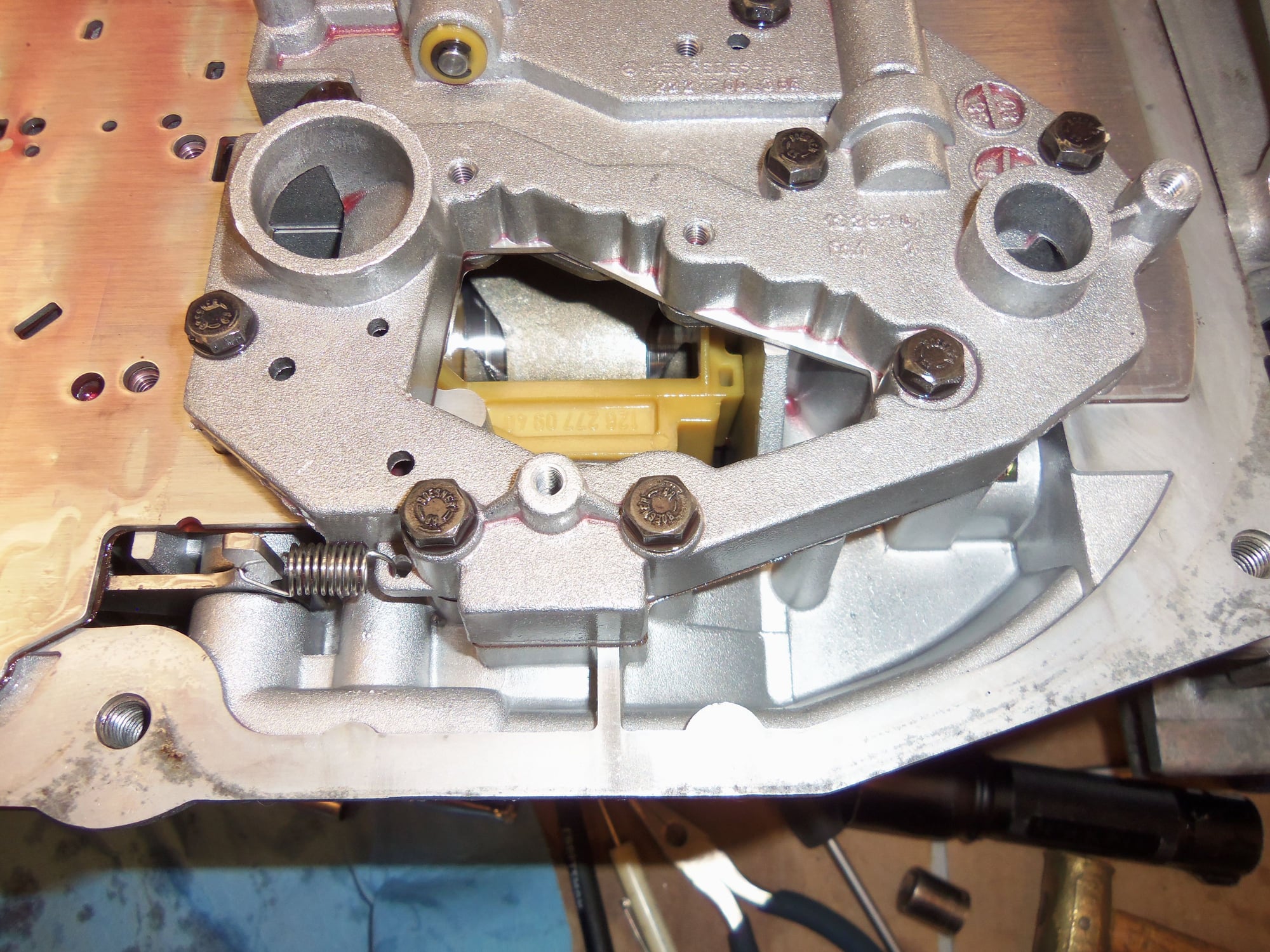
Parking pawl is the sorta brownish lever with the spring on it in the center. Mates into 'gear' on the output shaft. Yellow plastic guide is for the rod and roller that actuate the parking pawl.
Oil feed tube. WSM Volume 3 calls this an 'injector tube.' I am not 100% sure exactly what this lubricates.
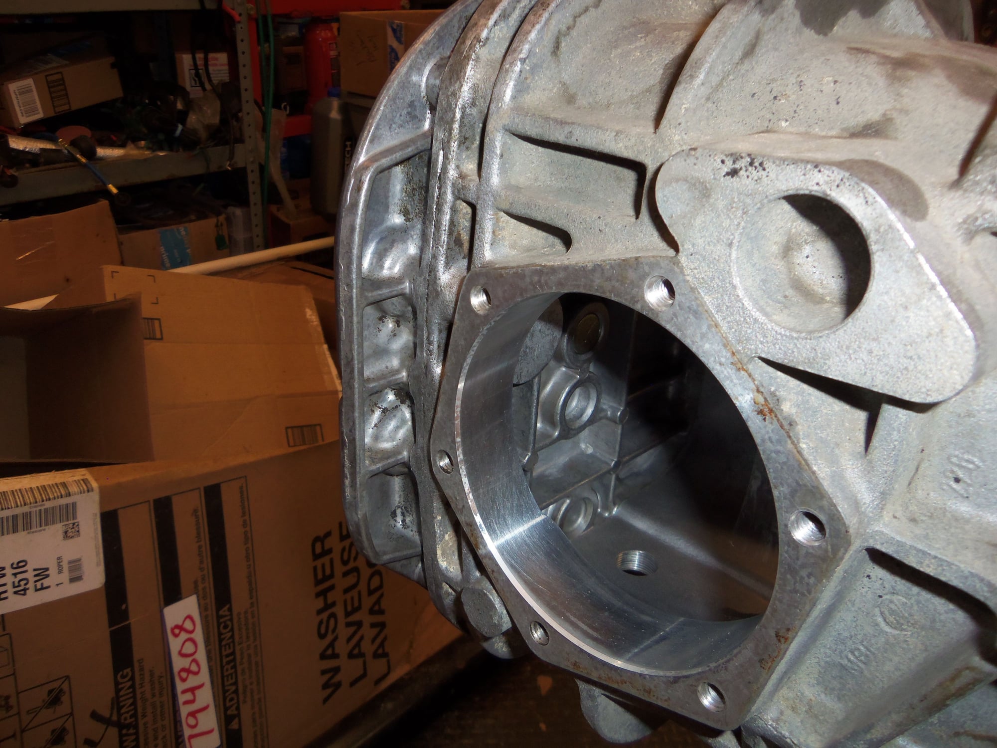
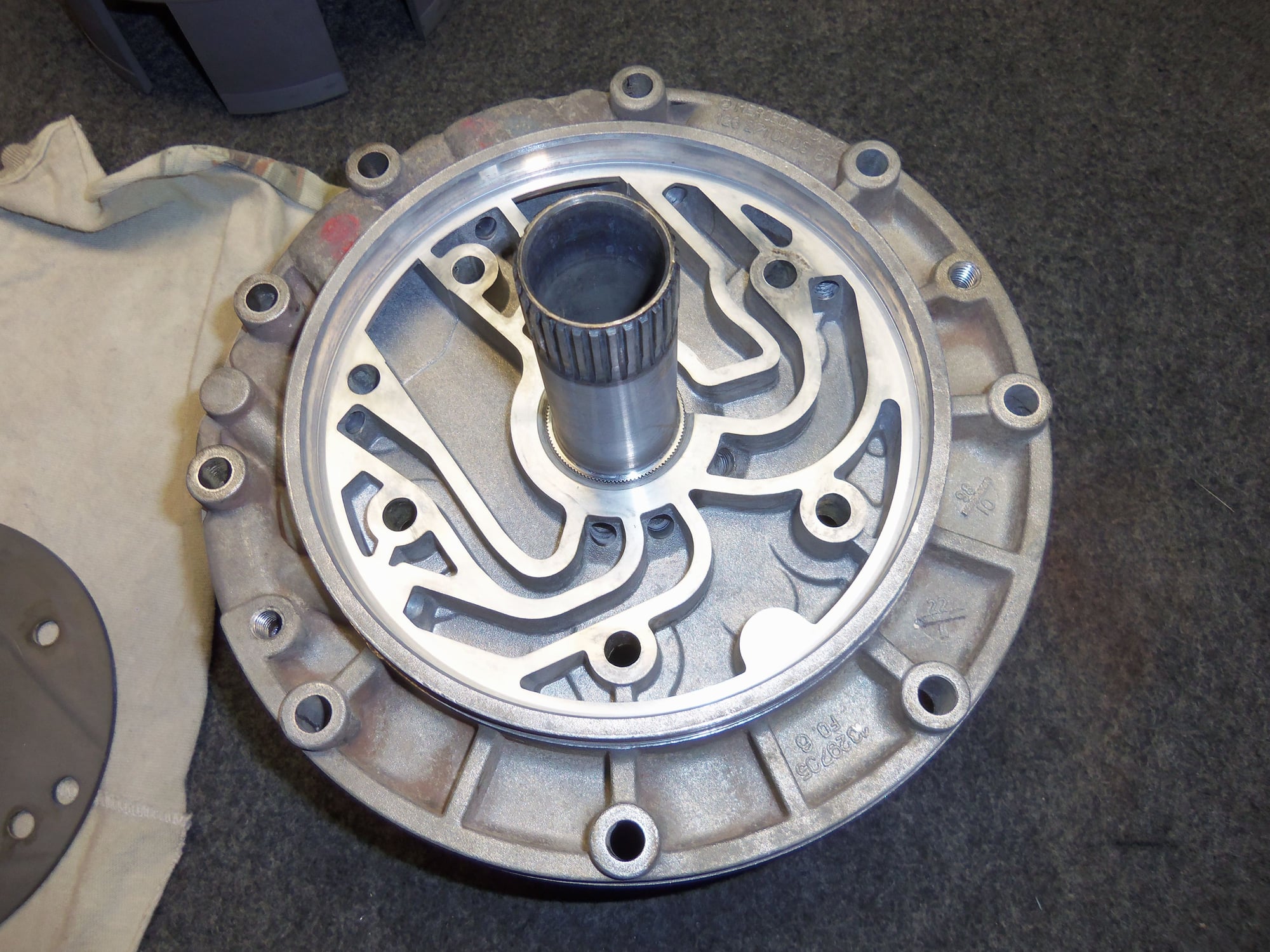
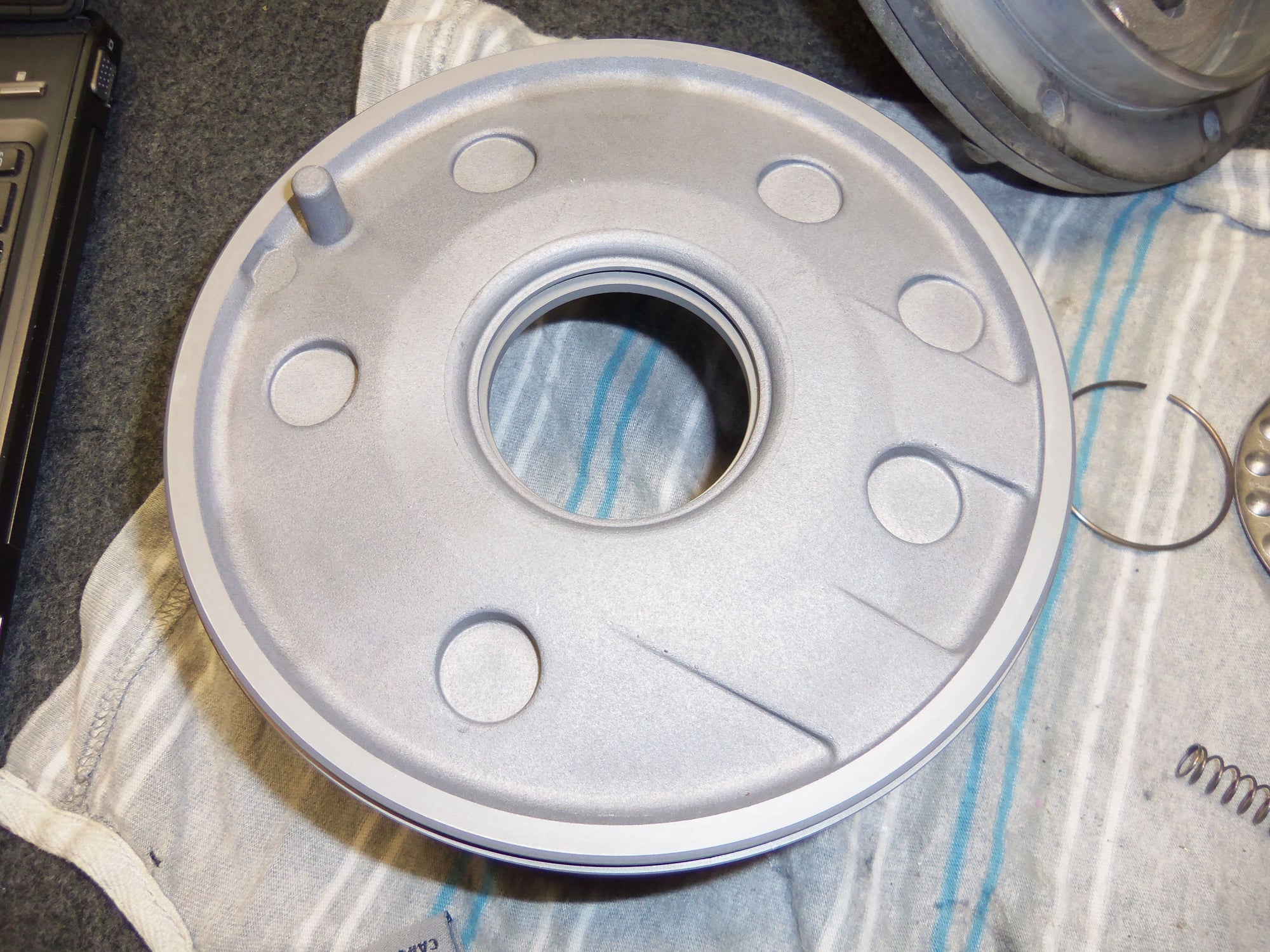
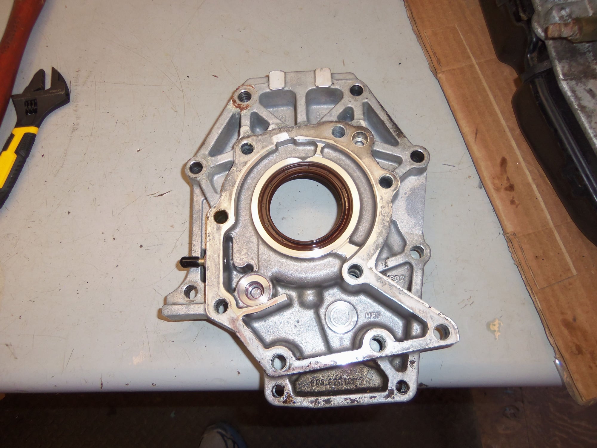
Separator removed from the back of the transmission.
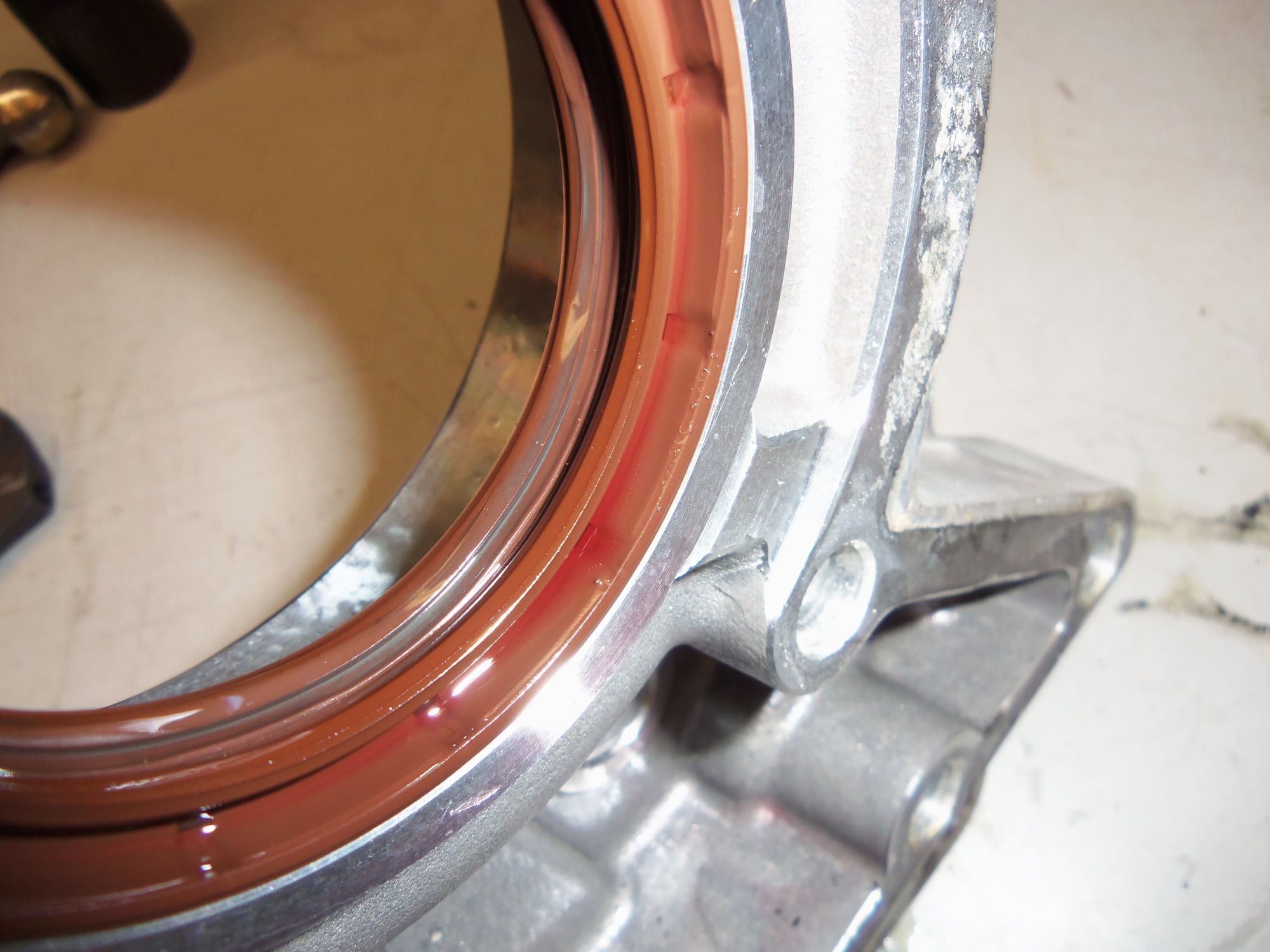
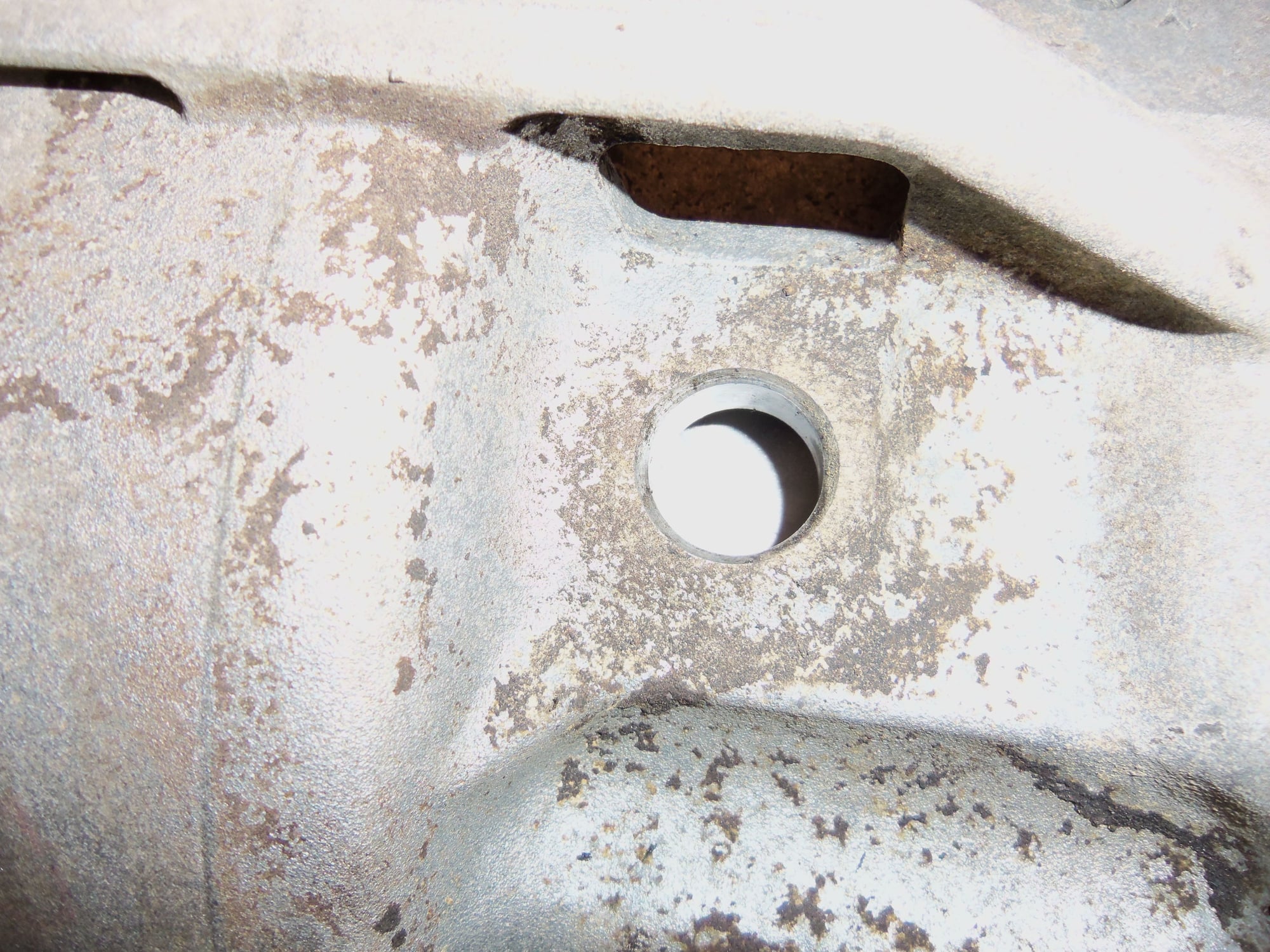
Trying to show the relationship of the 'weep hole' to the double radial seals. If gear oil or ATF makes it past either seal, it will flow out this weep hole.
Double radial seals, lips face towards the transmission and the differential.
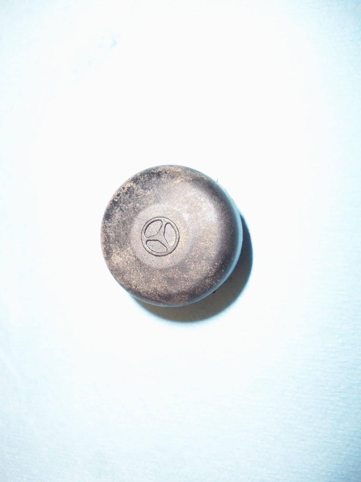
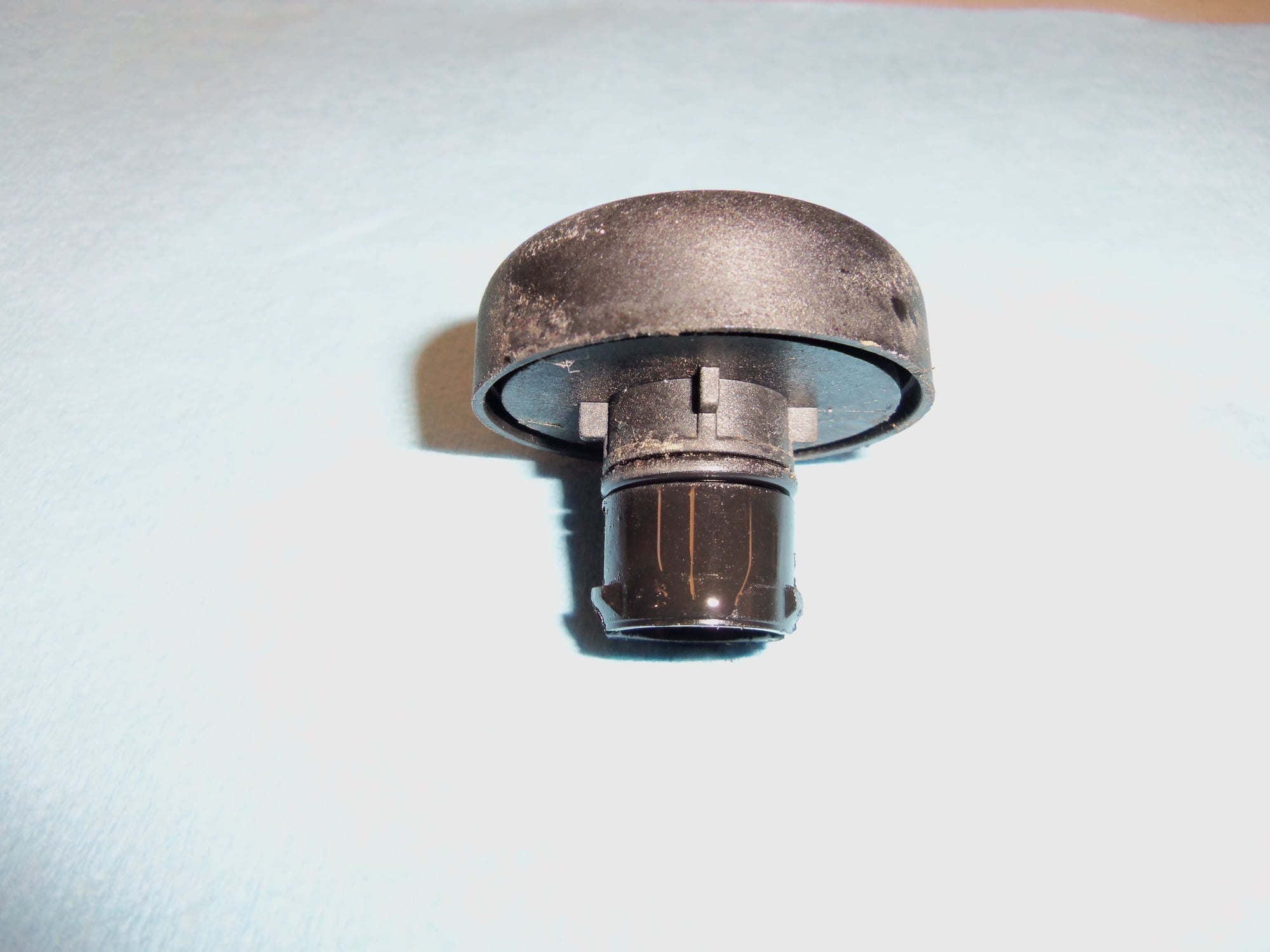
Removed the transmission case vent plug.
Little plastic thing, isn't it?
I believe there is a flapper valve in there.
Bore in the top of the casing for the vent plug.
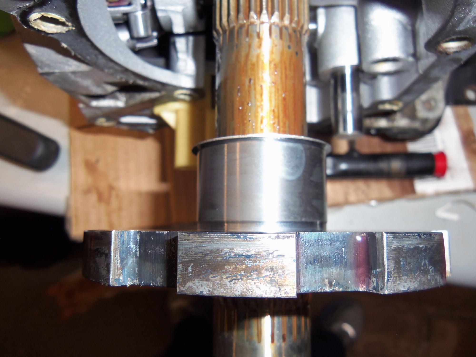
'Gear' on the output shaft for the parking pawl.
Sliding the gear off the shaft.
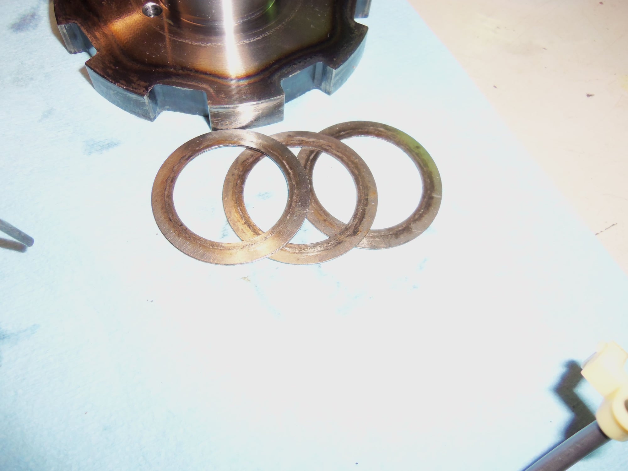
Washer starting to come with the gear.
Total of three washers behind the parking gear.
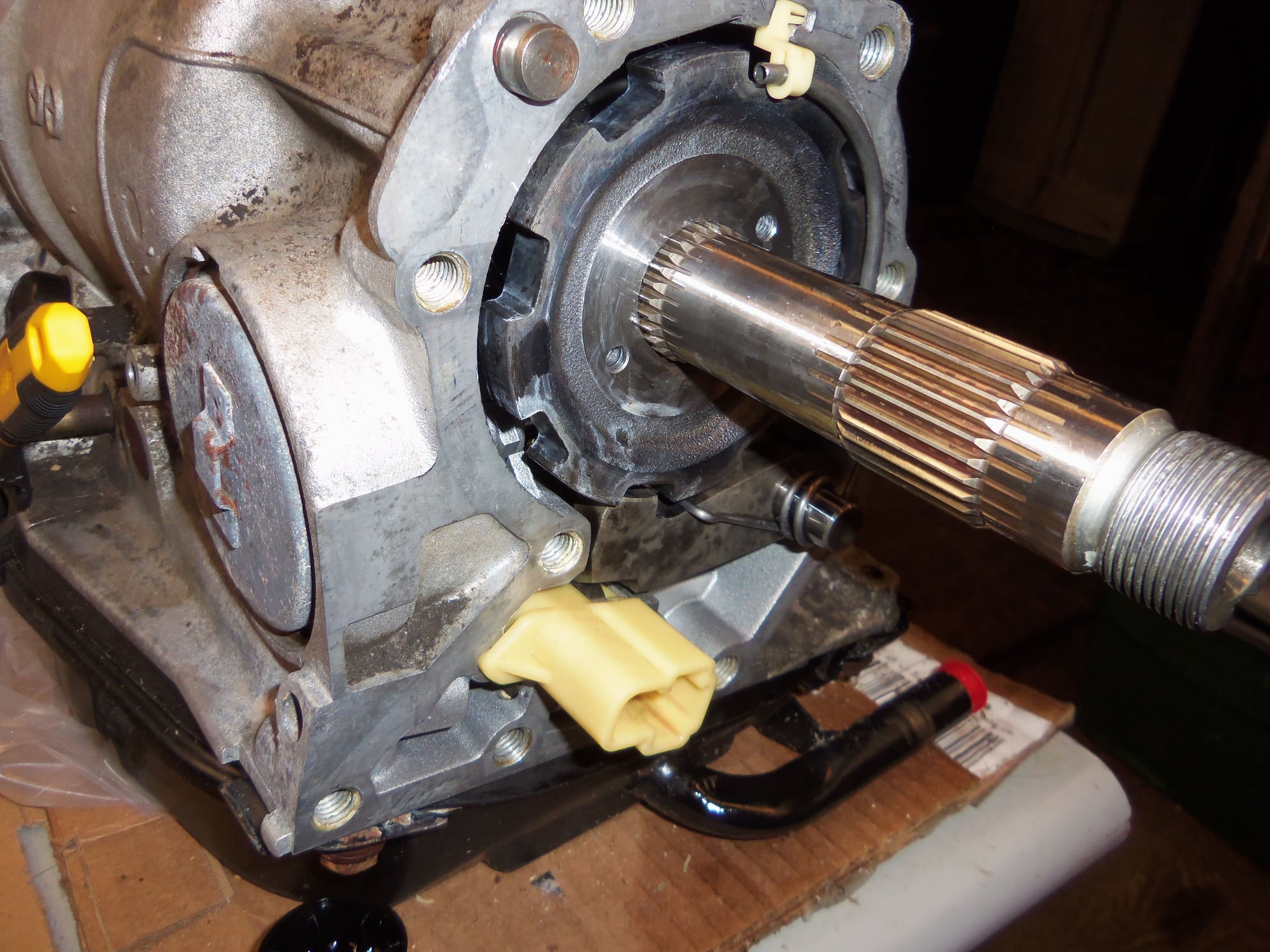
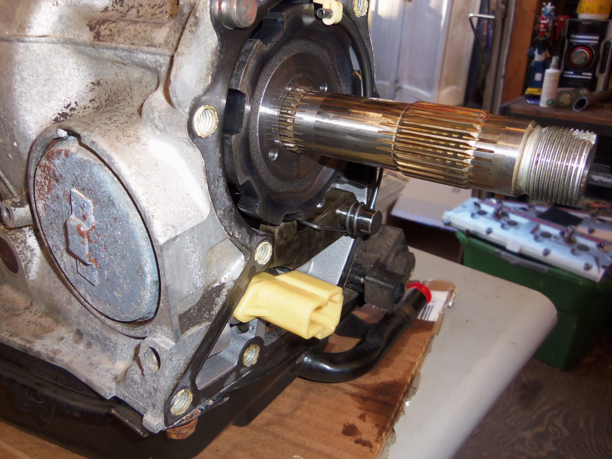
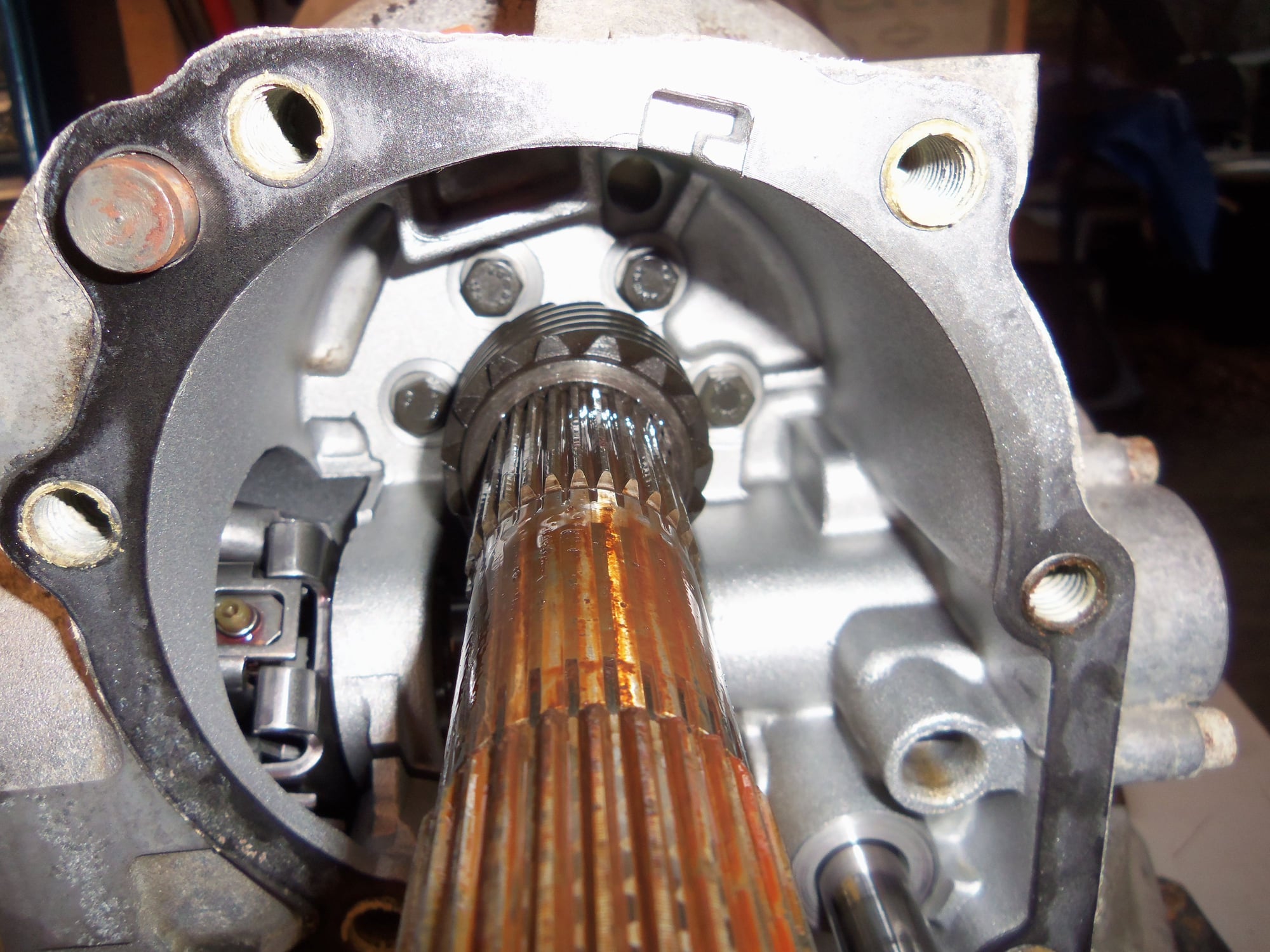
Looking deep into the casing at the governor drive gear teeth on the output shaft. Note the rusty residue on the output shaft. That has to GO!
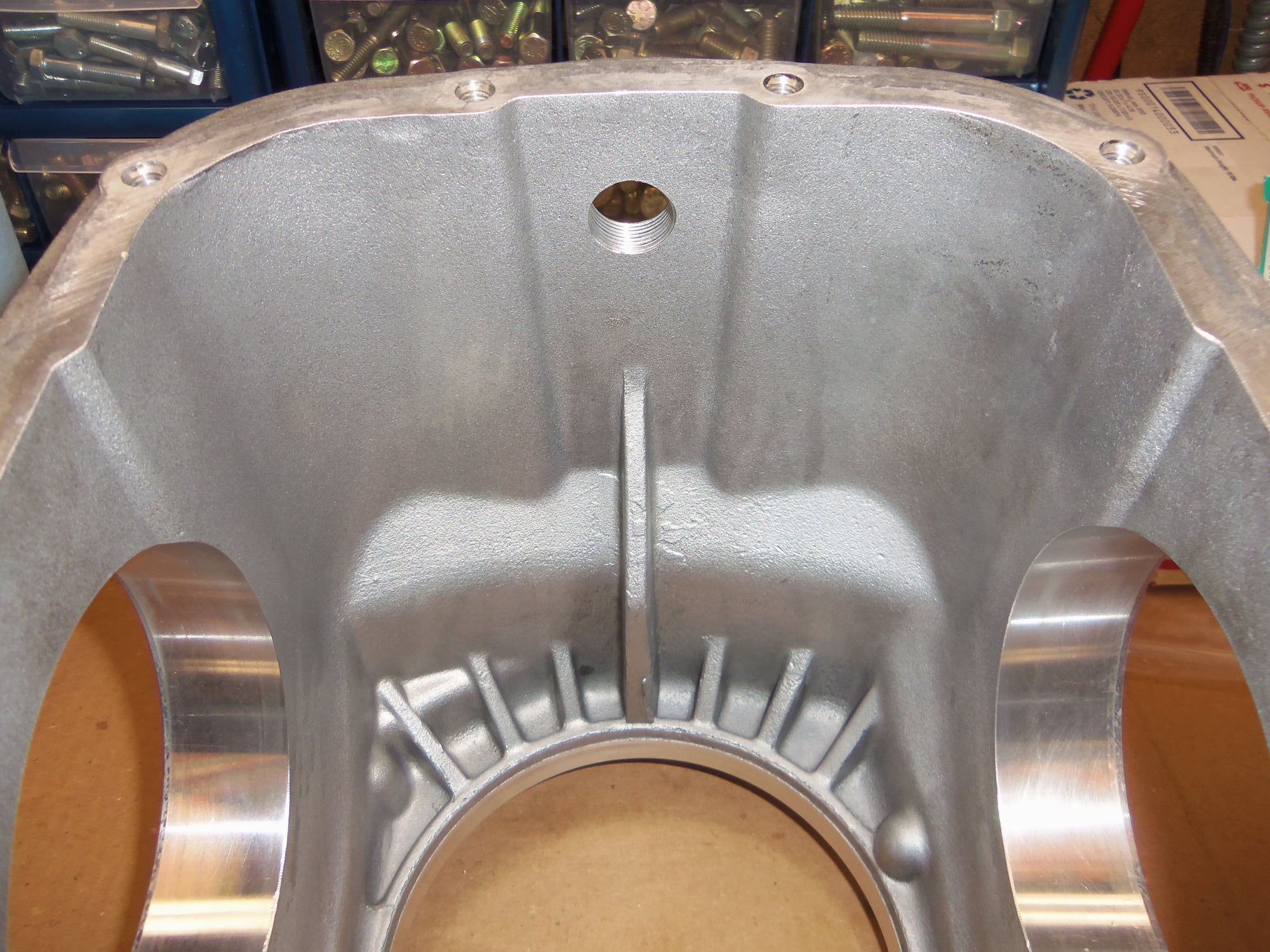
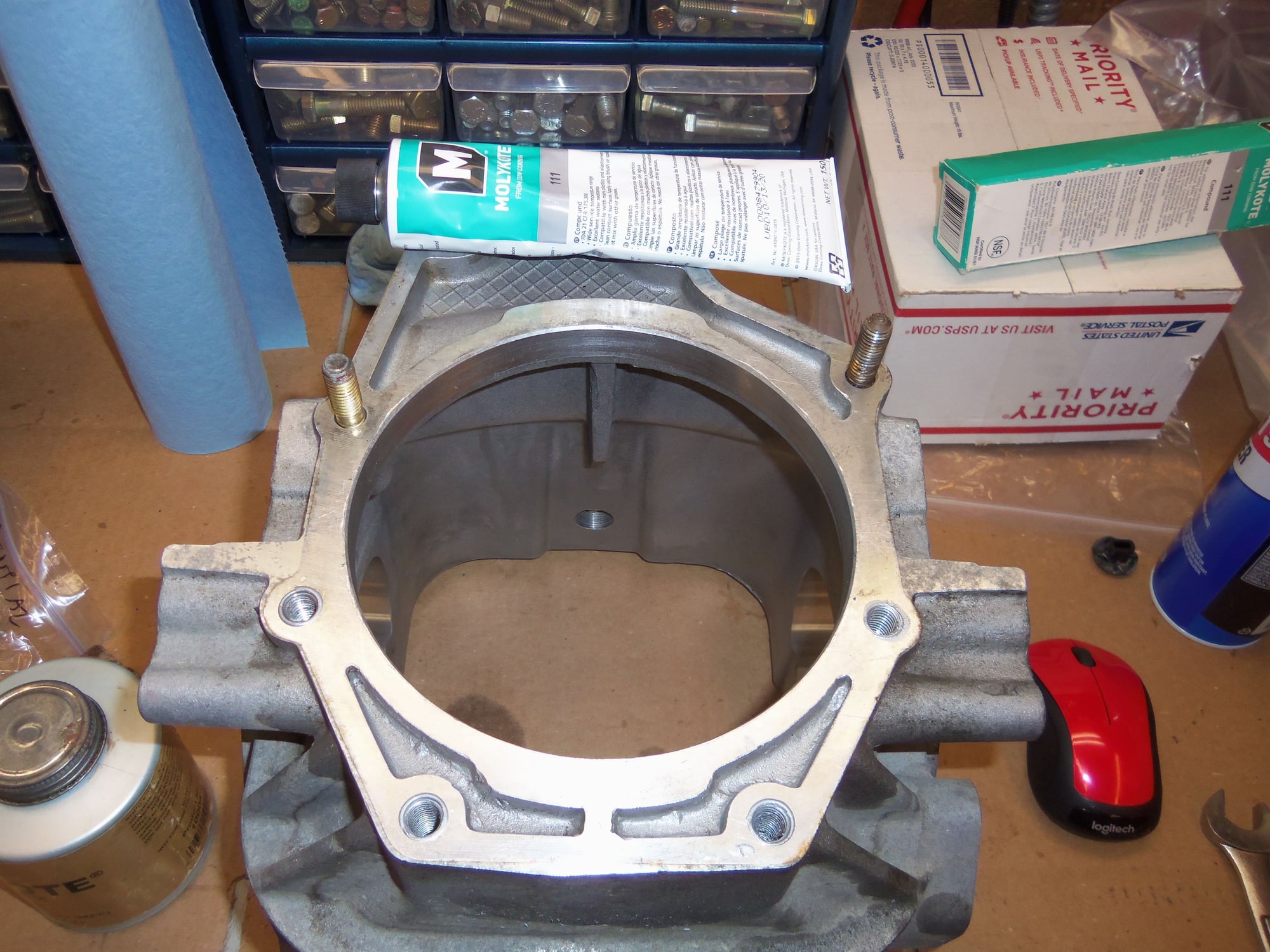
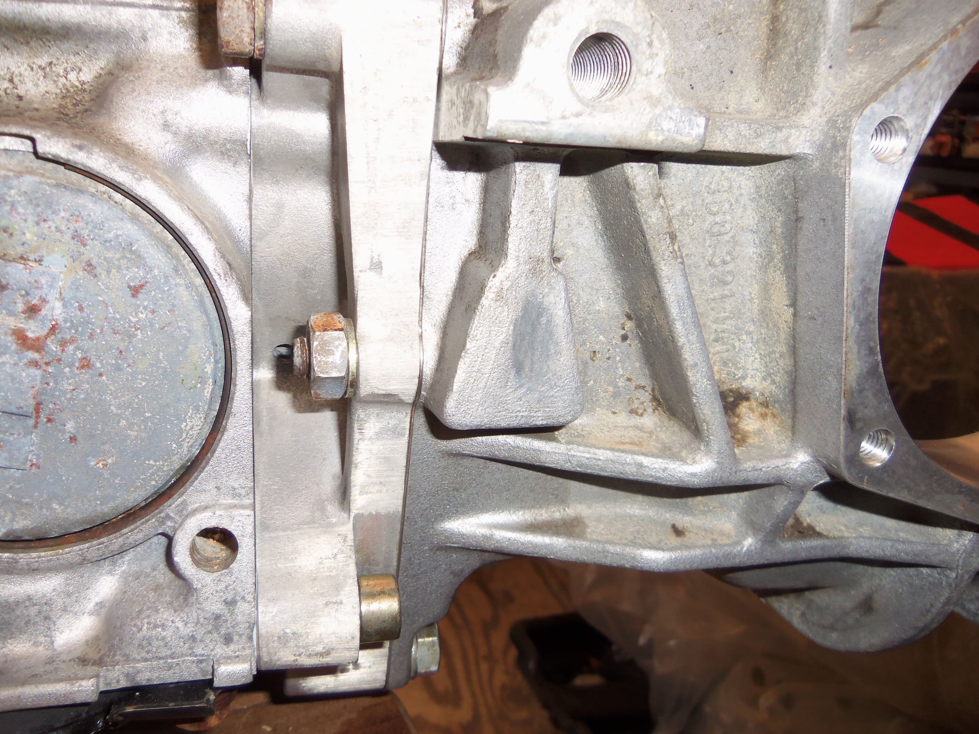
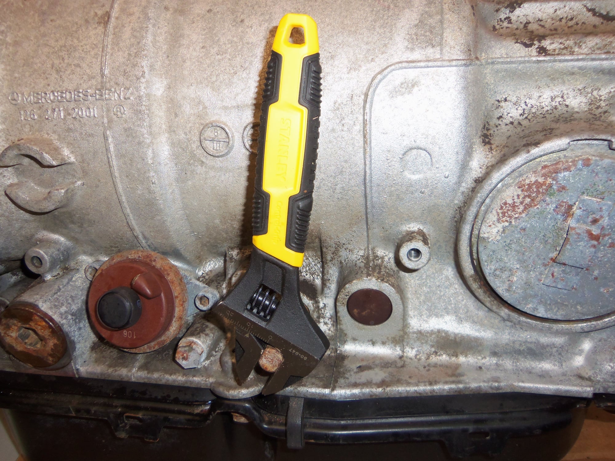
Governor drive cross shaft in the center, with oil feed tube, and yellow plastic shaft retainer. Note what looks like a crack in the casting of the left side governor cross shaft support. Look at the previous photo for another view of this 'crack.' It is actually a cut machined in on purpose. I am assuming it is to prevent deformation of the governor cross shaft support boss when the separator plate is bolted to the back of the transmission casing.
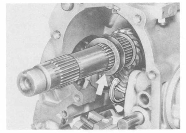
Note the machined cut in the casting near the governor cross shaft support in this screen shot from WSM Volume 3. It is supposed to be there.
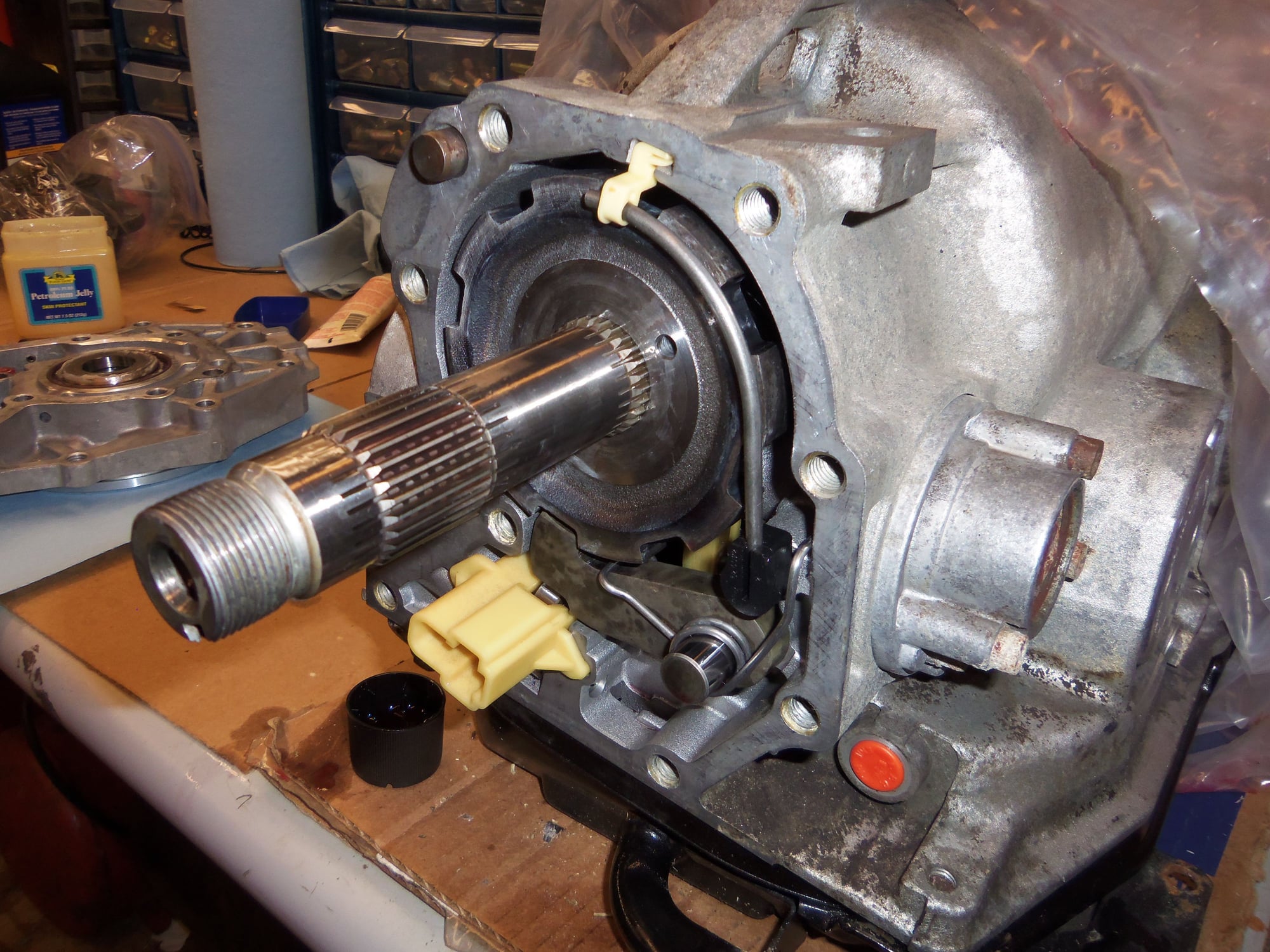
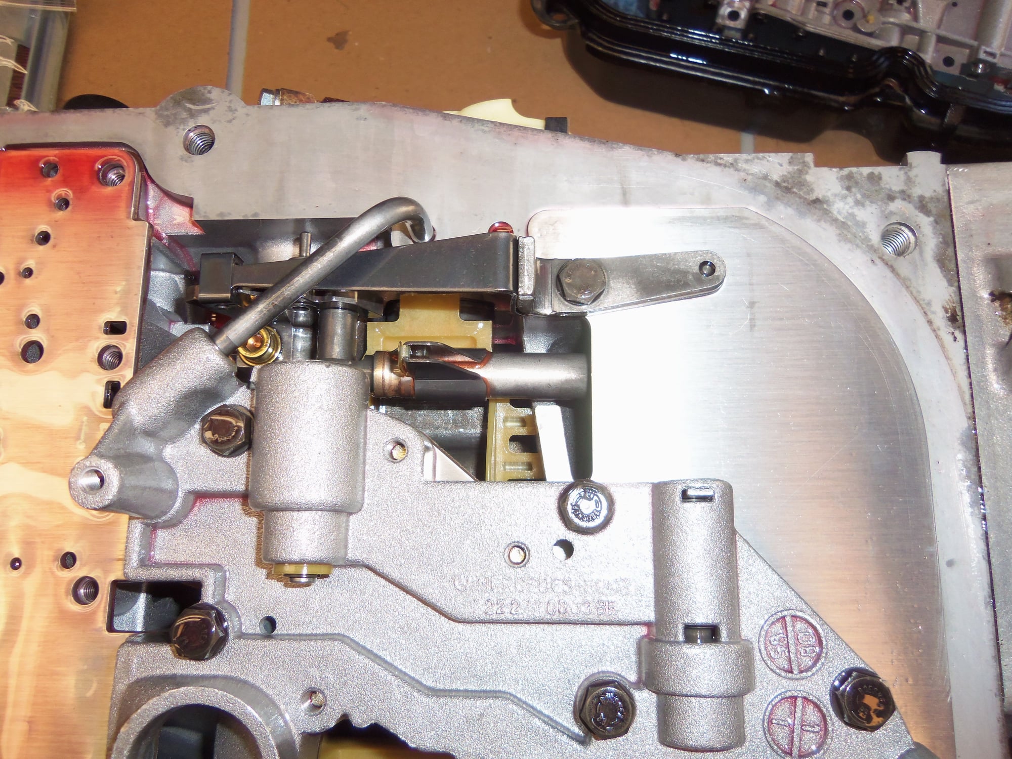
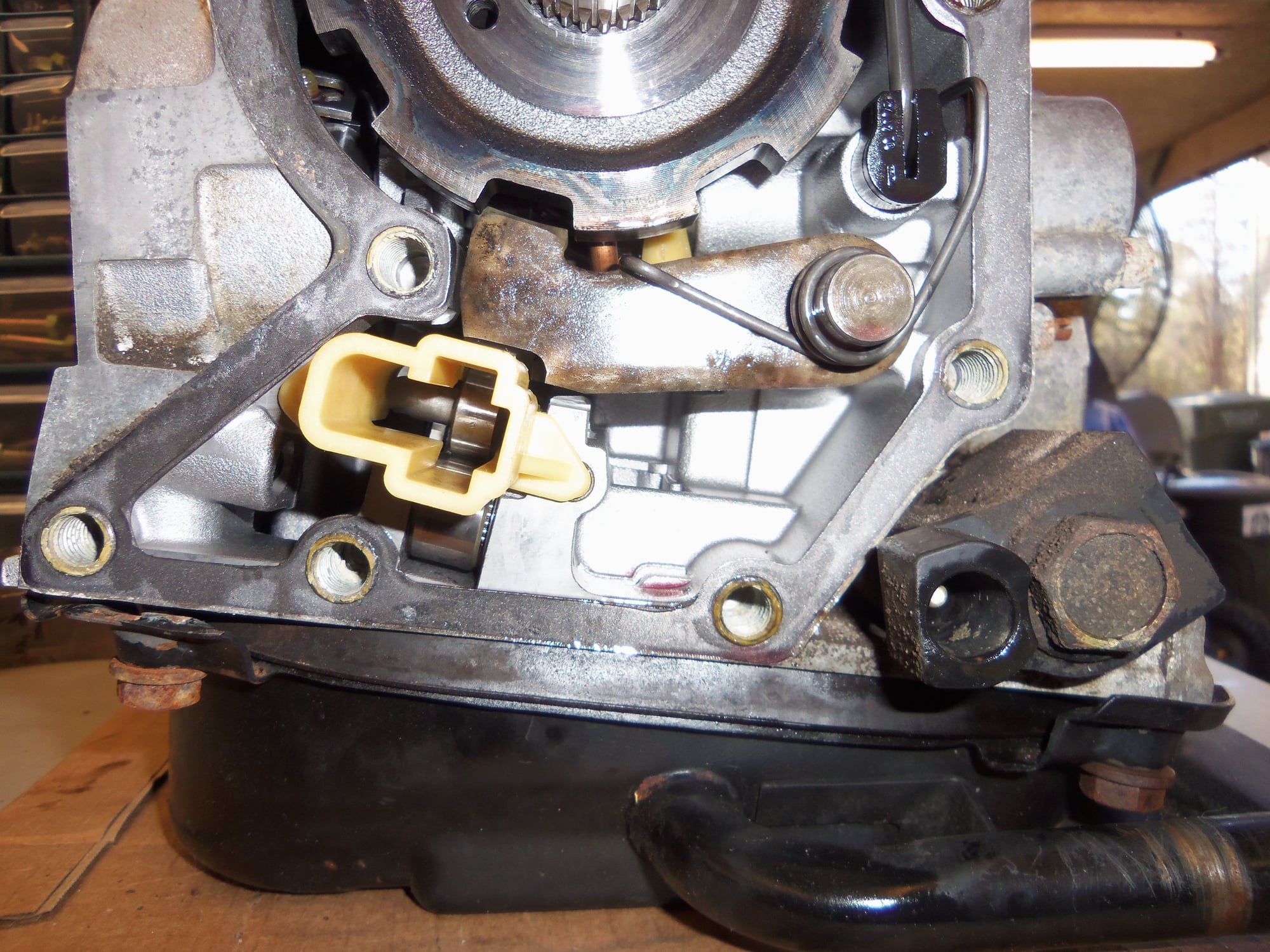
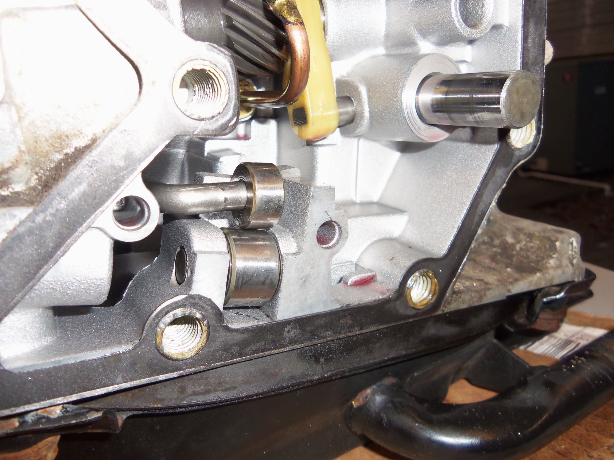
Parking rod roller and guide roller with the yellow plastic guide removed. Look really closely, and I believe you can see needle thrust bearings on the sides of the fixed guide roller at the bottom.
Yellow plastic guide just snaps into place in the back of the casing.
Manual gear selector shaft not in 'P'.
Rod and roller are retracted, parking pawl is not pushed up into the 'gear'.
Manual gear selector shaft is in 'P'.
Rod and roller are extended, which would push the parking pawl up into the teeth of the 'gear.' This would be what gives you that nasty CLICKETY noise if you put the shifter in 'P' with the vehicle still rolling.
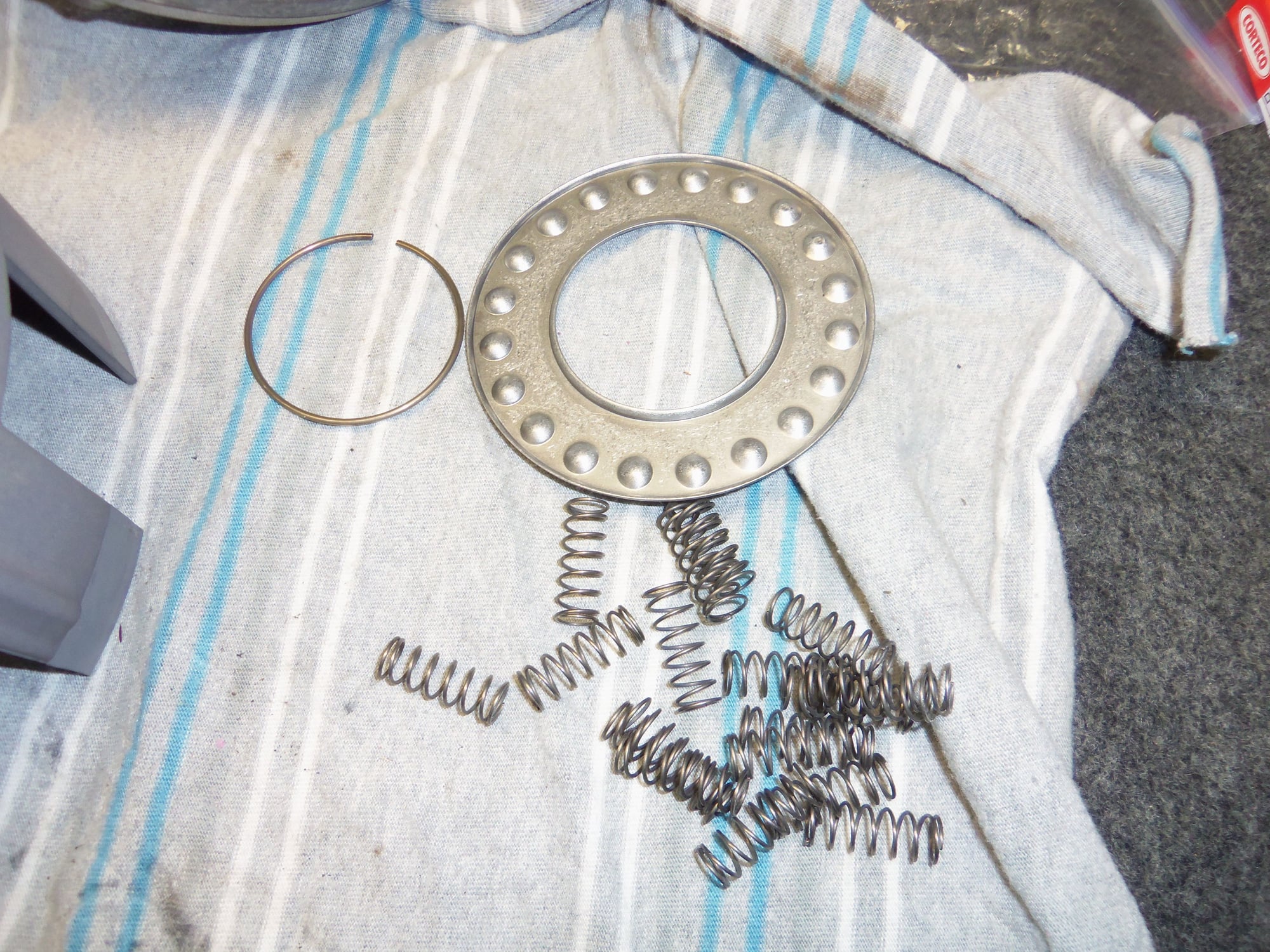
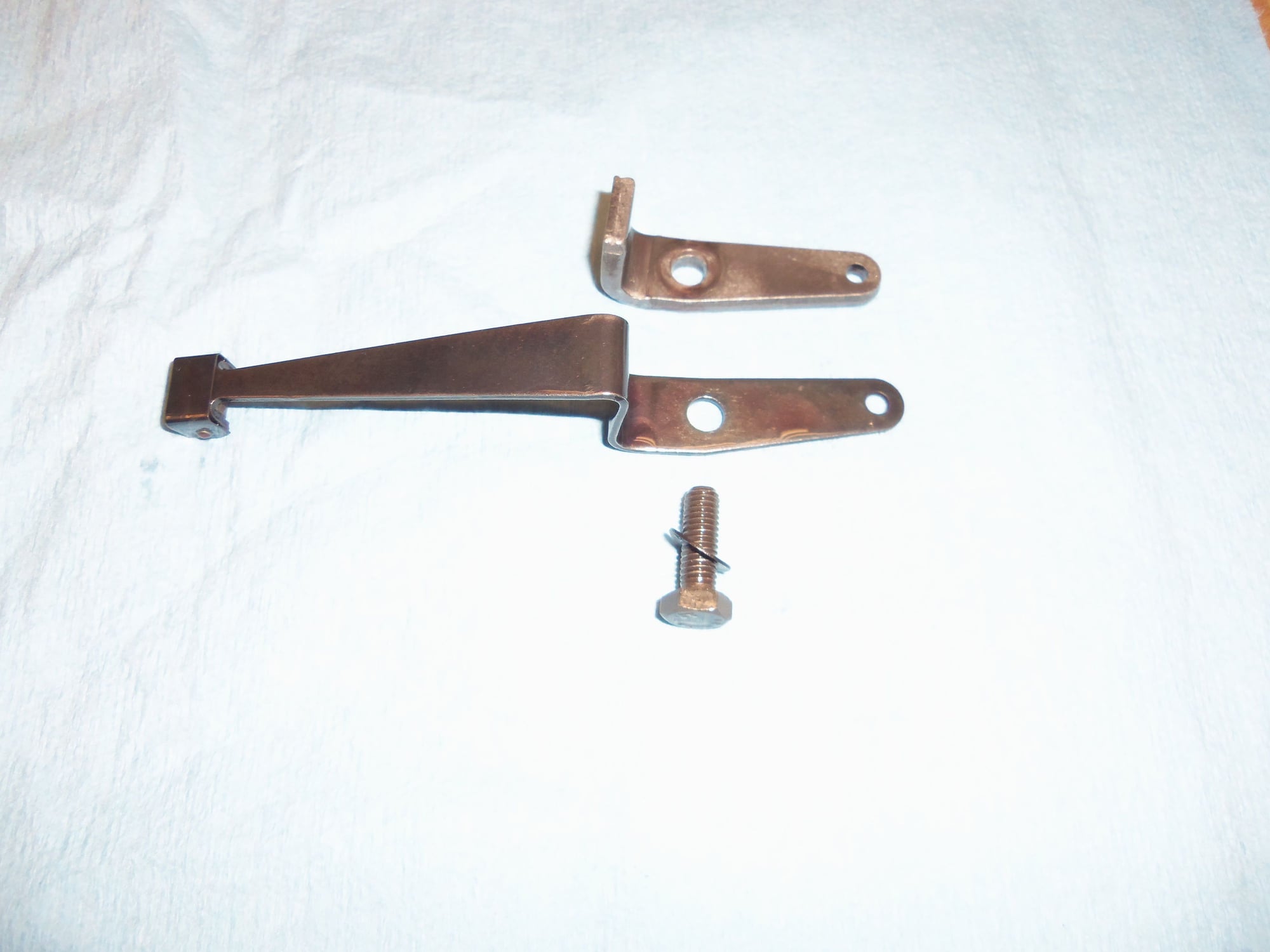
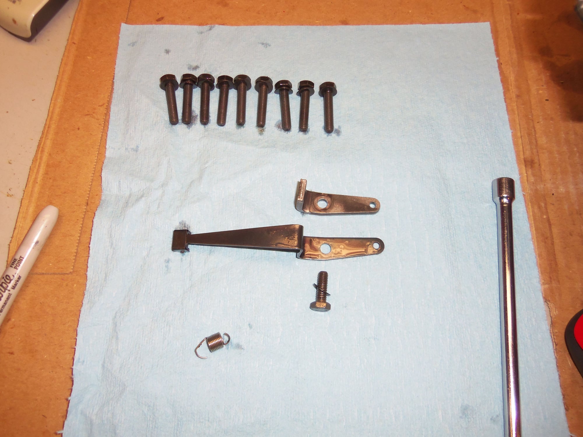
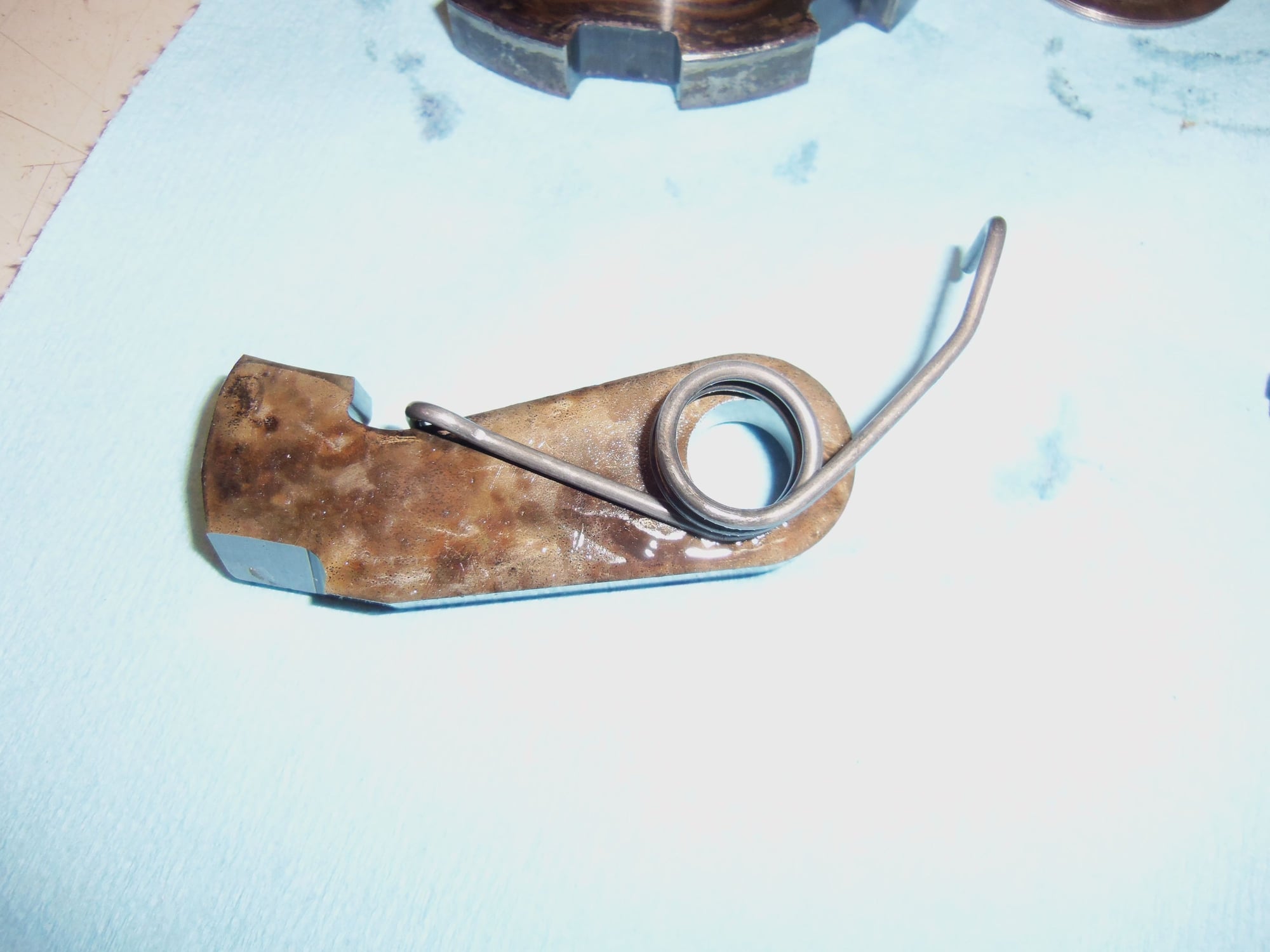
Parking pawl and return spring.
Parking gear and washer stack. Note the Mt. Dew can peeking in at the top of the photo. Helps me keep my sanity...
Washer stack separated.
It was neat figuring out how the parking pawl worked. With the manual gear selector shaft not in 'P', the rod and roller are retracted into the yellow plastic roller guide. The return spring keeps the parking pawl pulled down away from the parking gear. When the manual gear selector shaft is moved to 'P', the rod and roller are extended out of the yellow plastic roller guide. The roller contacts the bottom of the edge of the parking pawl. This pushes the pawl up into the teeth on the parking gear. If a space lines up, the pawl is pushed into it. If the pawl is up on a tooth, the vehicle will roll slightly forward or reverse until the pawl pushes up into the space between teeth.
Makes sense.
So, to make this short, I have thought about adding LSD, but am not going to at this time due to cost and complexity. Make sense?
Yes, it makes sense. I asked because when I rebuilt the gearbox on my 944 a couple of years back I bit the bullet and opted to install the LSD. In retrospect, I don't regret it. I managed to find a rebuilt ZF LSD for the Audi box, I don't have any experience with the auto Mercedes transaxle, I'll assume the tooling needed to install the LSD correctly is every bit as expensive as the VW/Audi tools used for the AOR trans on the 944. I looked at doing it myself but like you decided it was cost prohibitive so I ended up sub-contracting the install to a local specialist.
In my case I was able to source a rebuilt LSD for about $1100, then I ended up paying another $850 to have it and a short 5th gear installed. I also had to buy all the seals (maybe another $200) and I decided to put in the factory trans. oil cooler at the same time (about $200 more). All told I think the entire rebuild cost about $2200 including shipping, but like you I removed and installed the gearbox myself, it would have been a lot more if I'd taken the whole car in.
I can say it made a huge difference in the way the car performs though; more than a little noticeable. Well worth the time and money. In my case it took almost a year because the guy I hired to install the LSD moved shops in the middle of the project, so he had the thing about 8 months. But I sure like the results!
I agree that LSD would make a difference in how the Red Witch handles, especially with the uprated rear anti-sway bar, Koni's, and Eibach's that are going in. But, I get ahead of myself.
IF I should trip over a reasonably priced way to add LSD to the Red Witch BEFORE I install the transmission back in the car, I would probably take it.
Otherwise, she will stay peg-leg. For now.
Only a couple more things to remove before LOTS of cleaning.
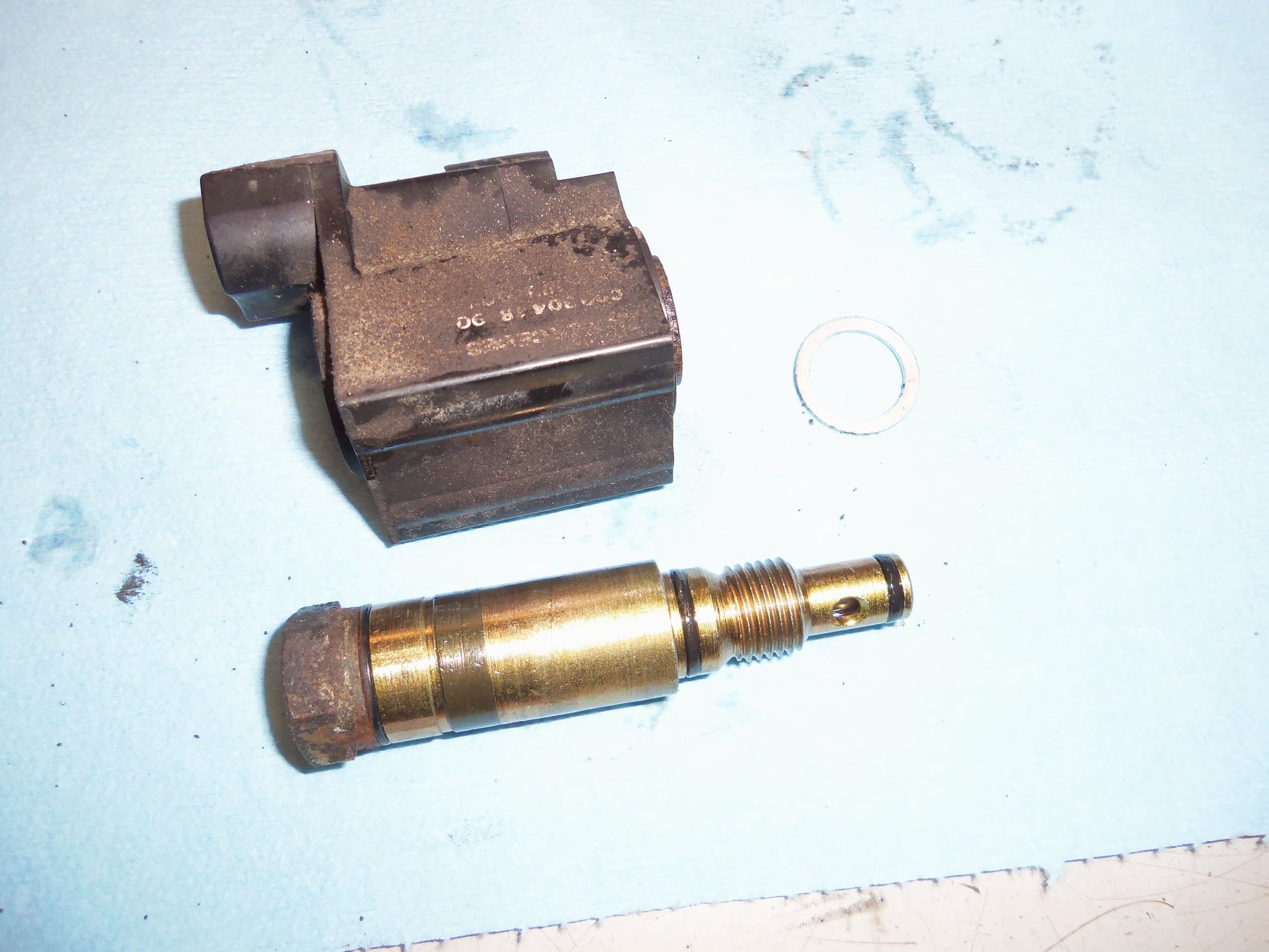
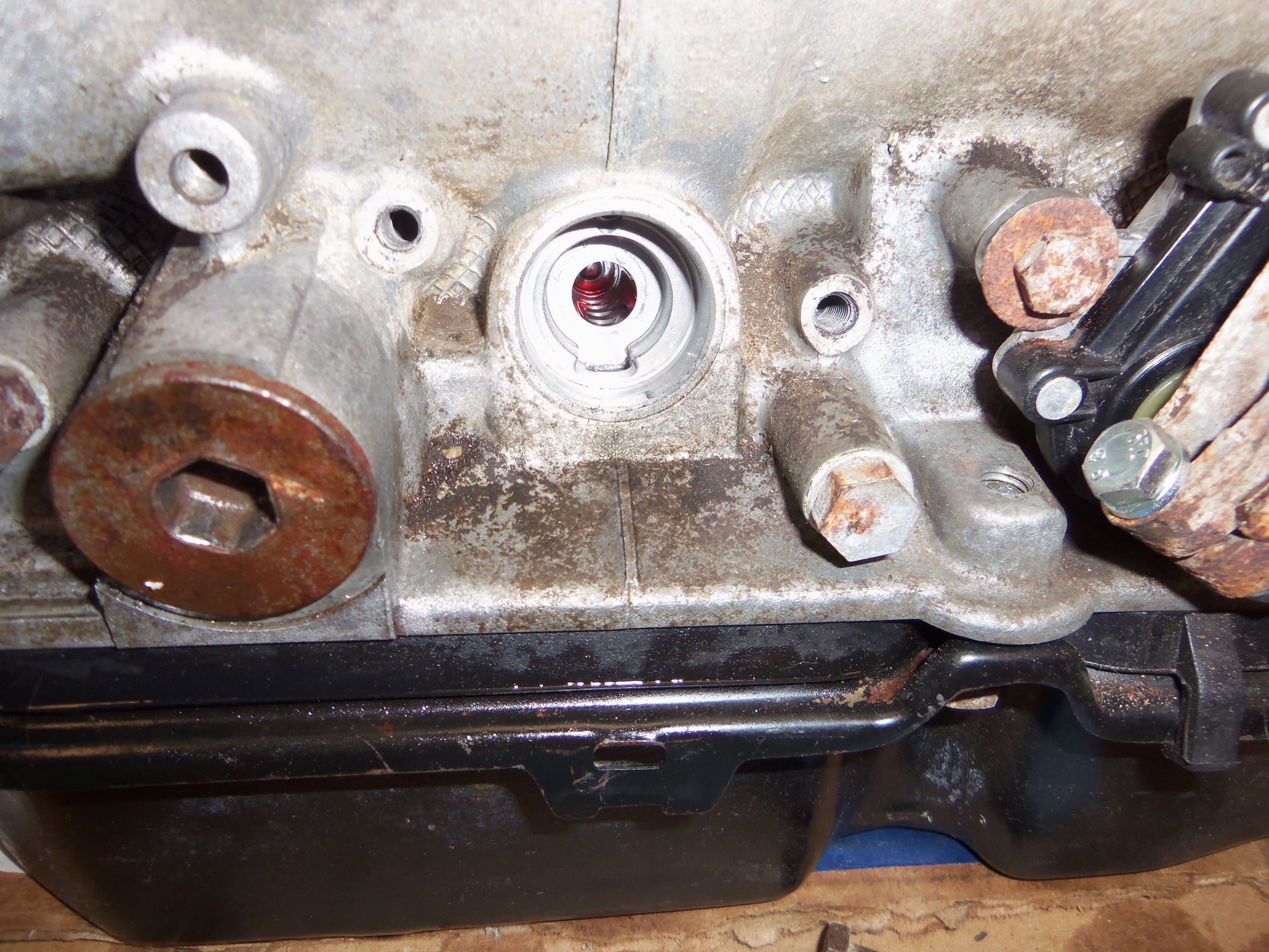
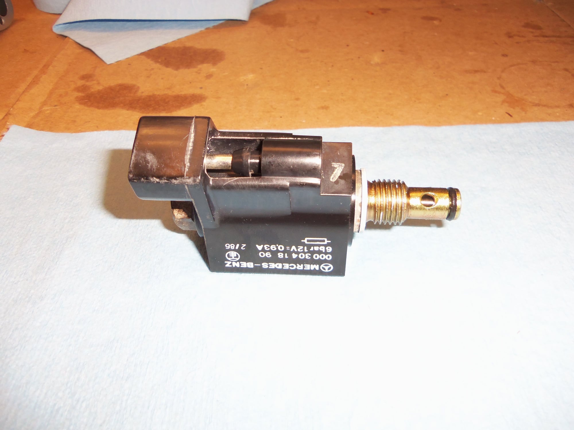
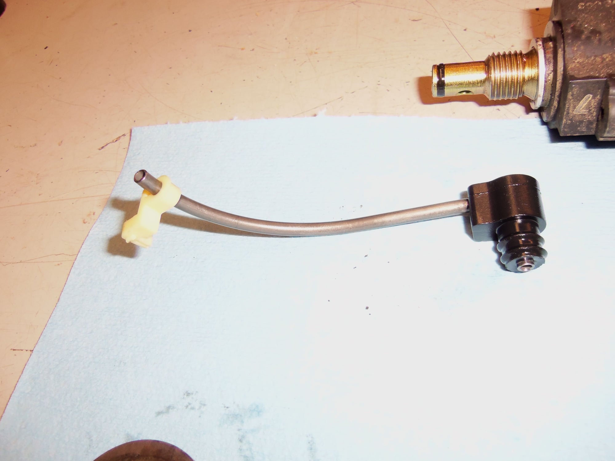
Pulled the kickdown solenoid coil and stem from the back of the transmission casing, as well as the old vacuum modulator from the side.
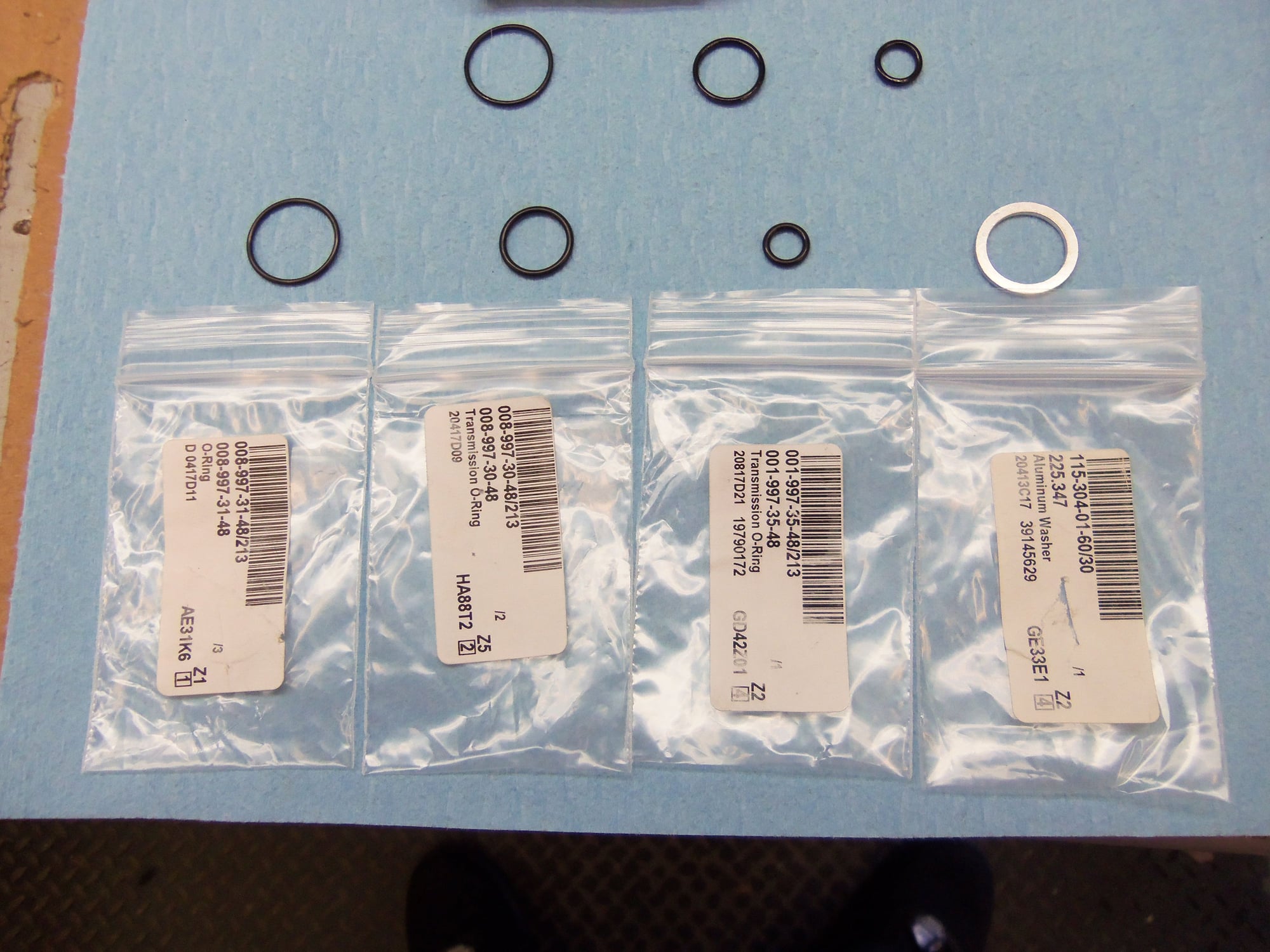
Kickdown solenoid coil and pressure stem. Note three O-rings on stem, and aluminum crush washer for sealing stem to casing.
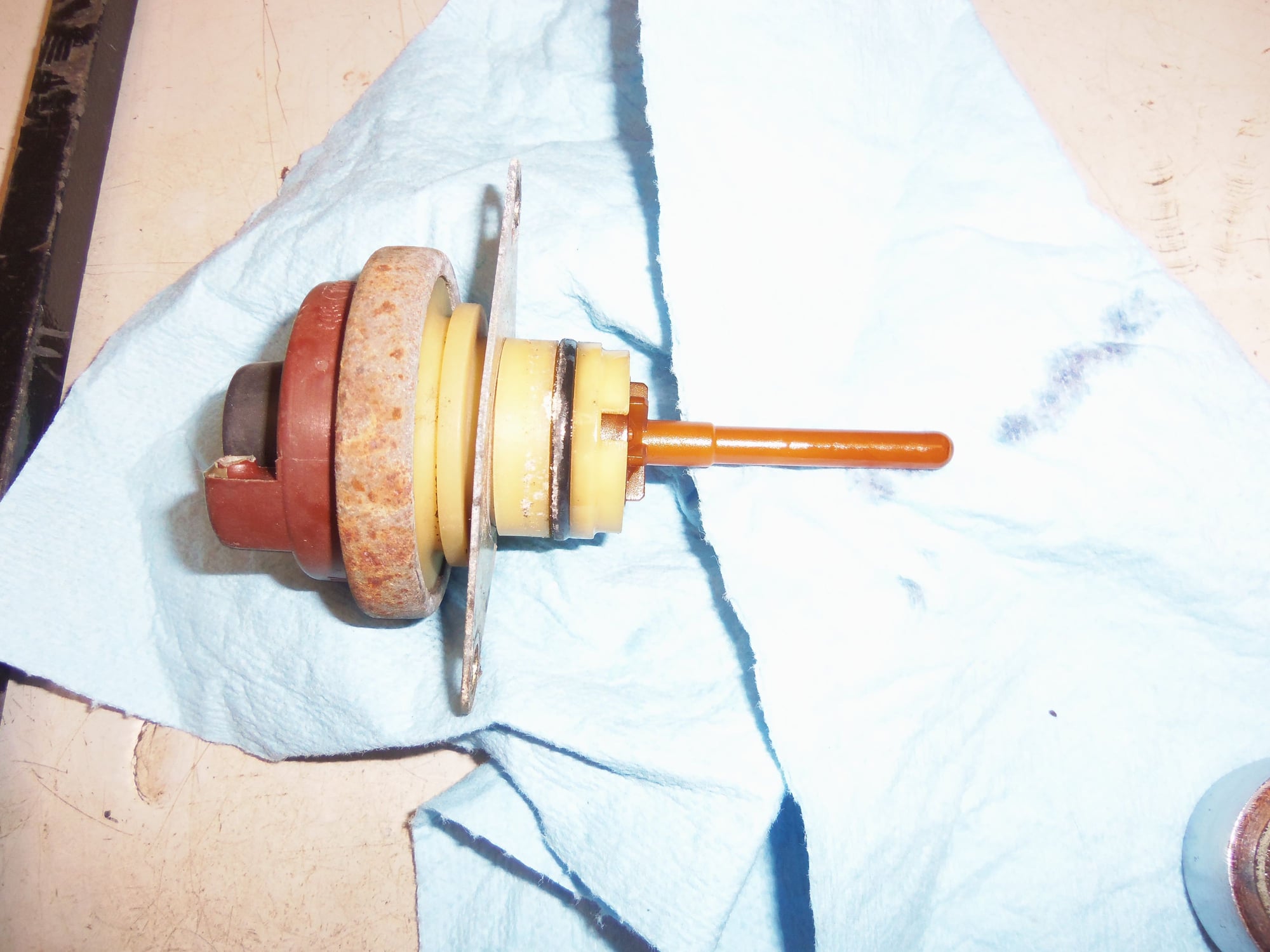
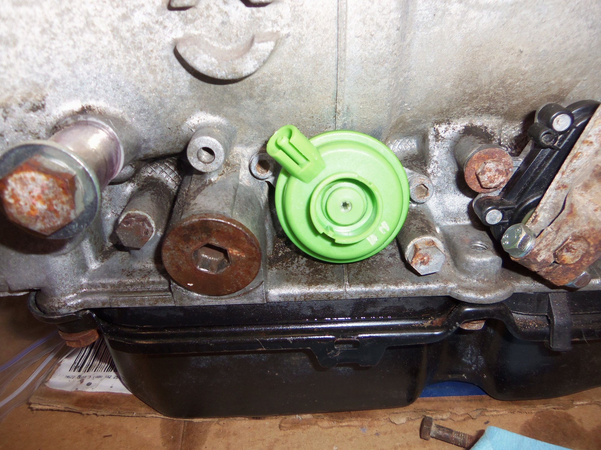
Old, and possibly original, vacuum modulator, with plastic pin installed.
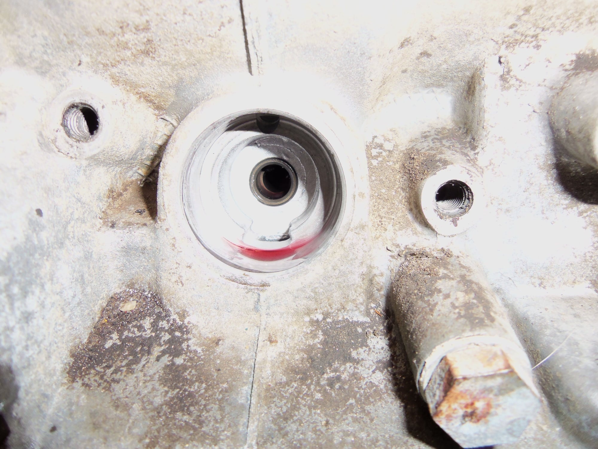
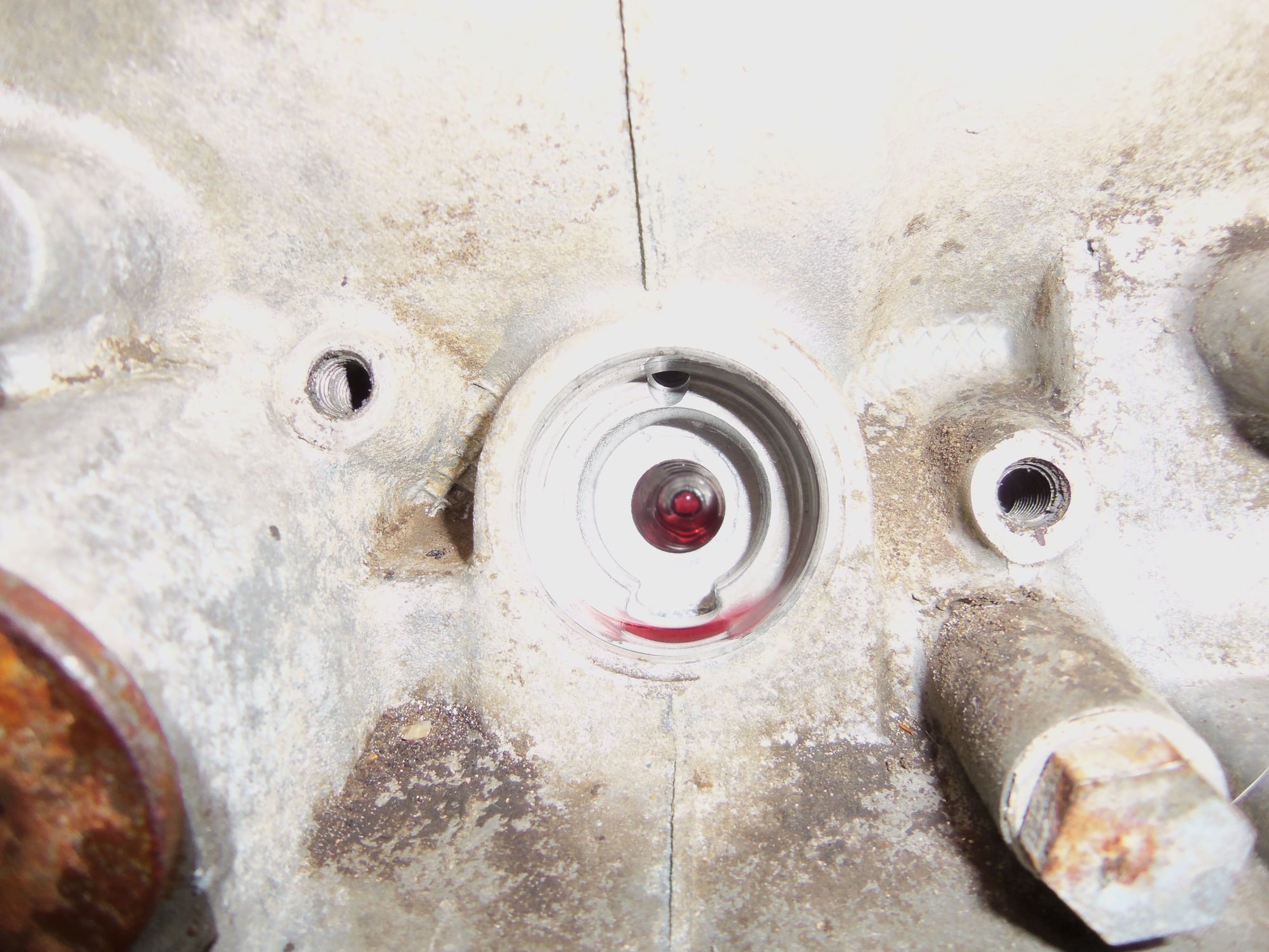
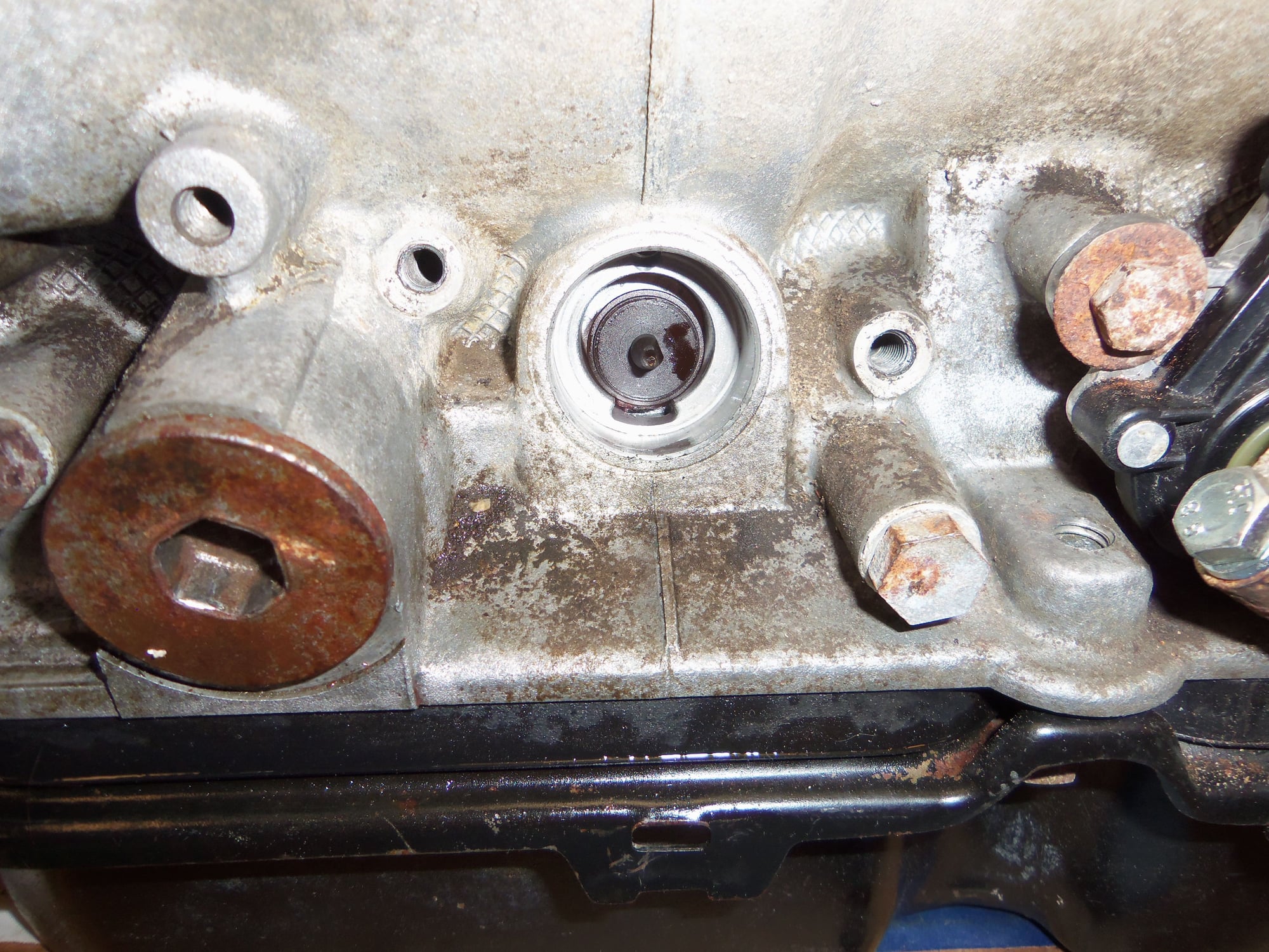
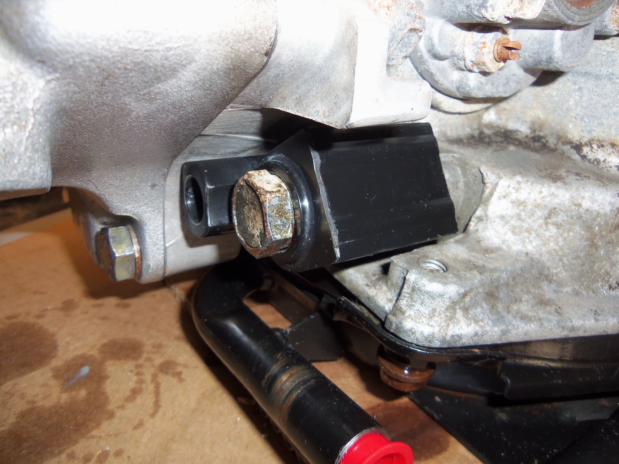
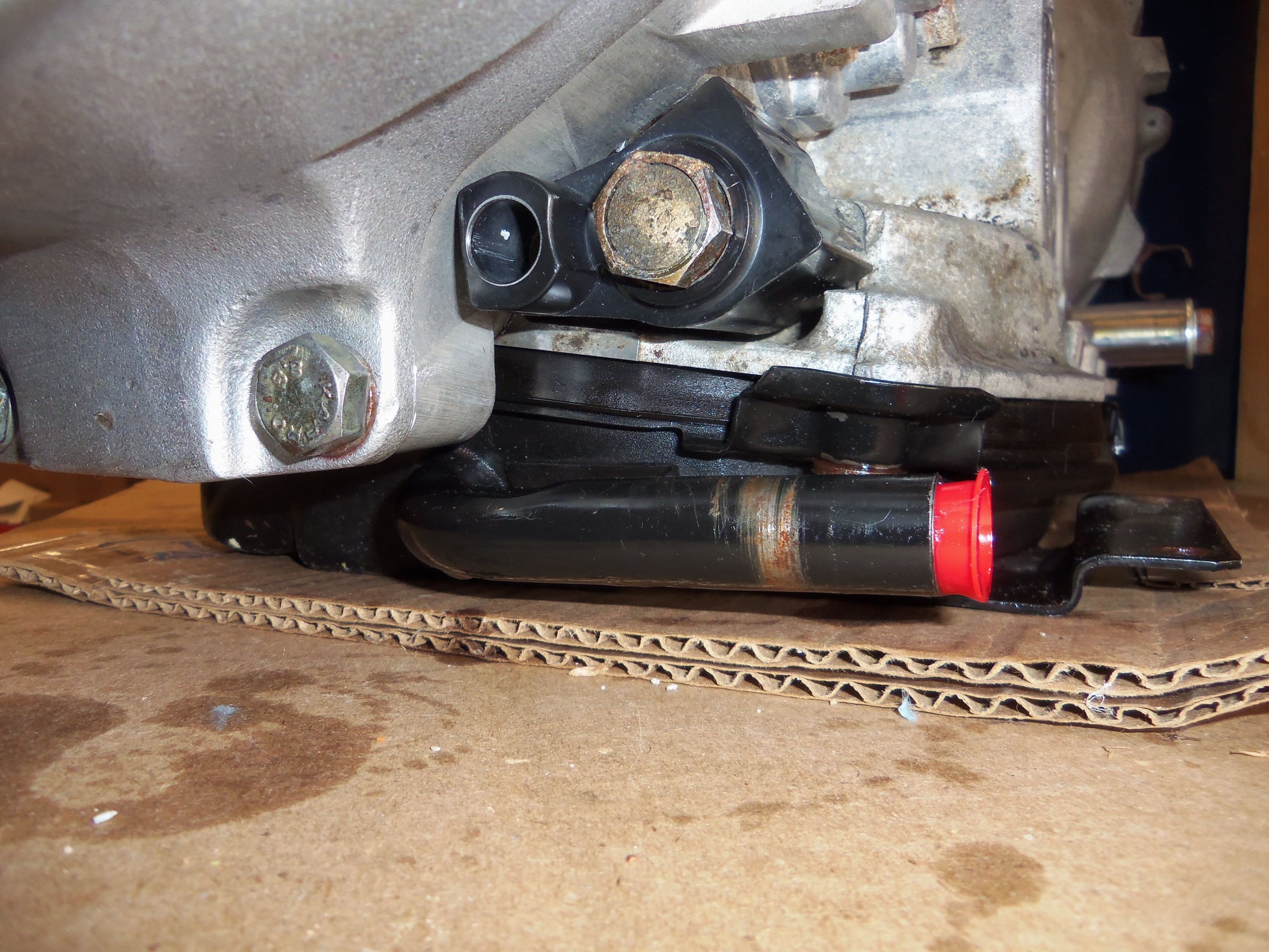
Bore in transmission casing for vacuum modulator, showing piston still down in bore.
Piston removed with vacuum modulator.
Empty bore.
This was as far as I wanted to go for disassembly of the rear of the transmission and such. So...MUCHO cleaning followed. All parts had seals, O-rings, gaskets, etc...removed, then spent time in the heated parts washer at work. Lots of scrubbing with various brushes removed most of the crud from the parts, except for the really baked on stuff. Because the Red Witch will be a driver, I am not overly concerned with removing every last bit of dirt from the OUTSIDE.
All machined and sealing surfaces were treated far more thoroughly. Many razor blades were used to remove gaskets, but no scotch-brite. Finally, everything was liberally rinsed with contact cleaner and/or brake cleaner. Hardware was cleaned then had a thread chaser tap or die run down or into the threads. All threaded holes were chased then blown out with brake cleaner. Great care was taken to keep dirt, debris, and gasket shreds from getting into the transmission casing.
All shims were cleaned then scrubbed with scotch-brite to remove any corrosion.
Then, the fun of reassembly could begin!
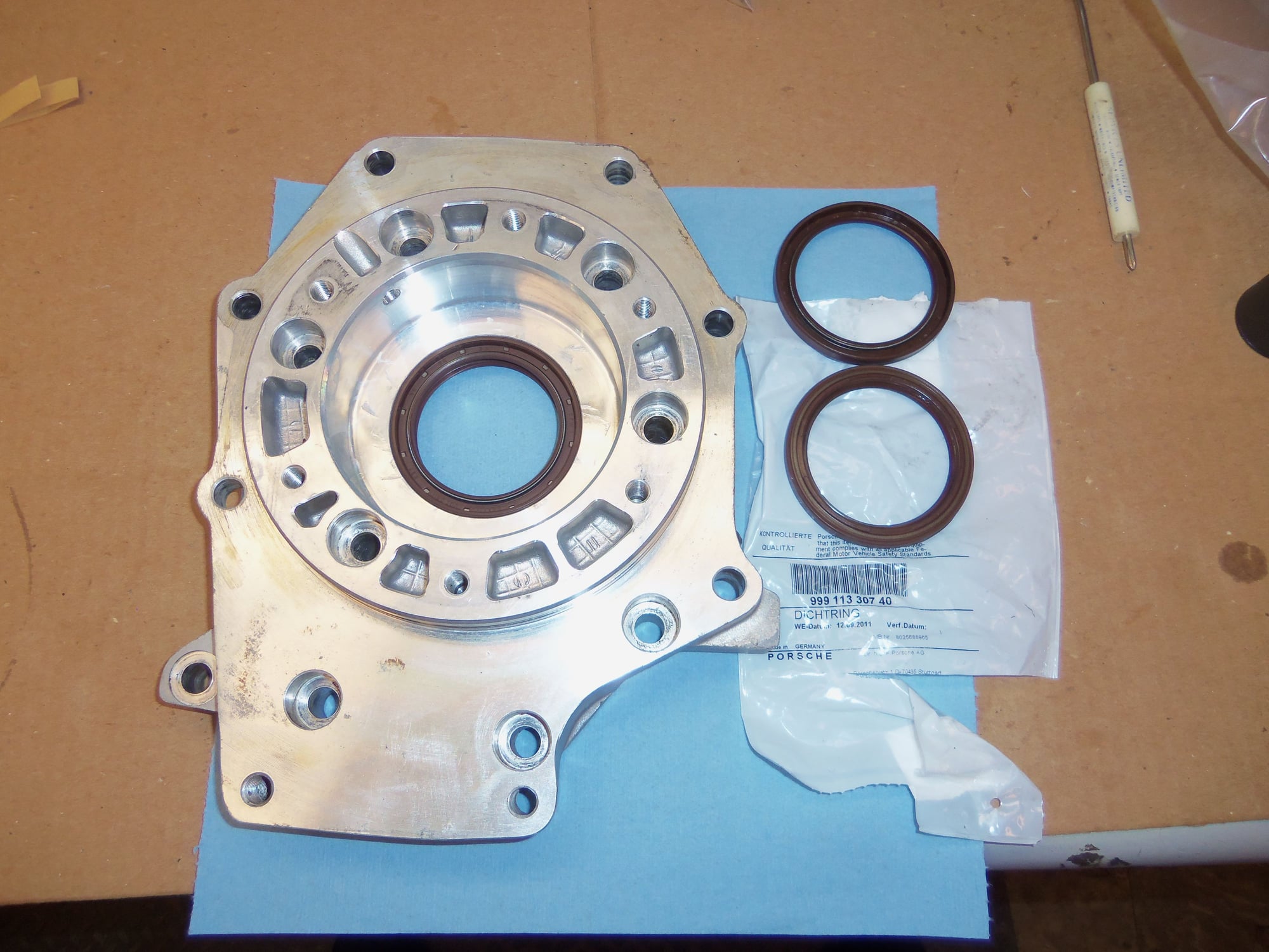
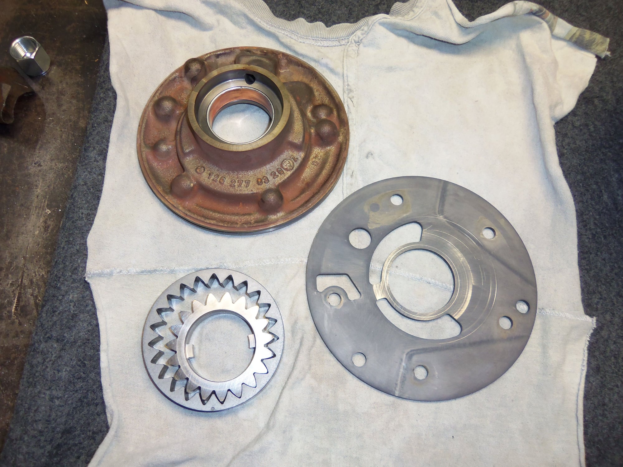
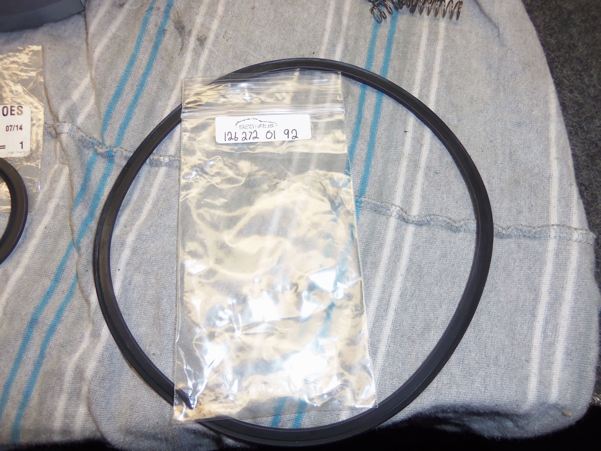
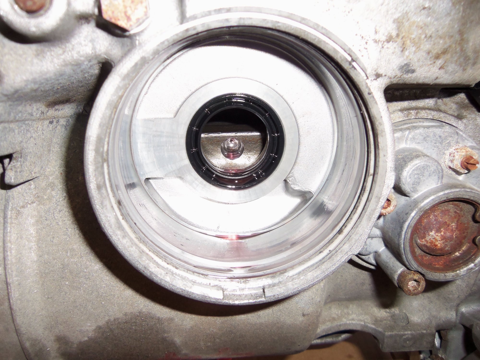
Separator plate with new radial seal installed for differential side, old seals to the side.
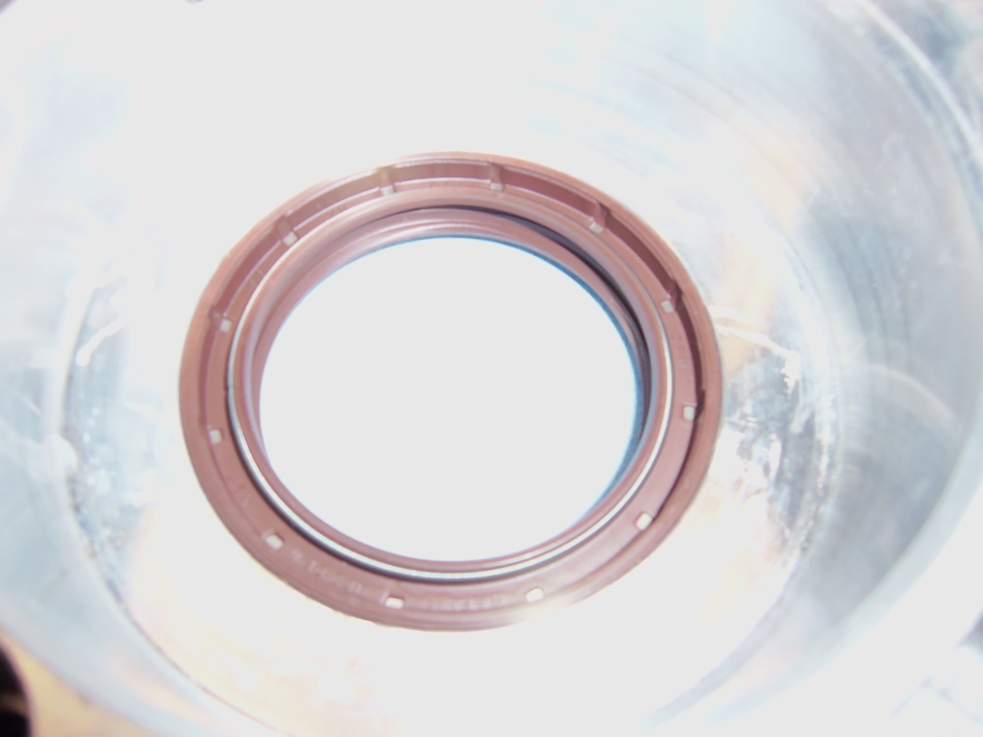
New radial seal installed flush with the surface, lip facing the differential, just as the old one was installed.
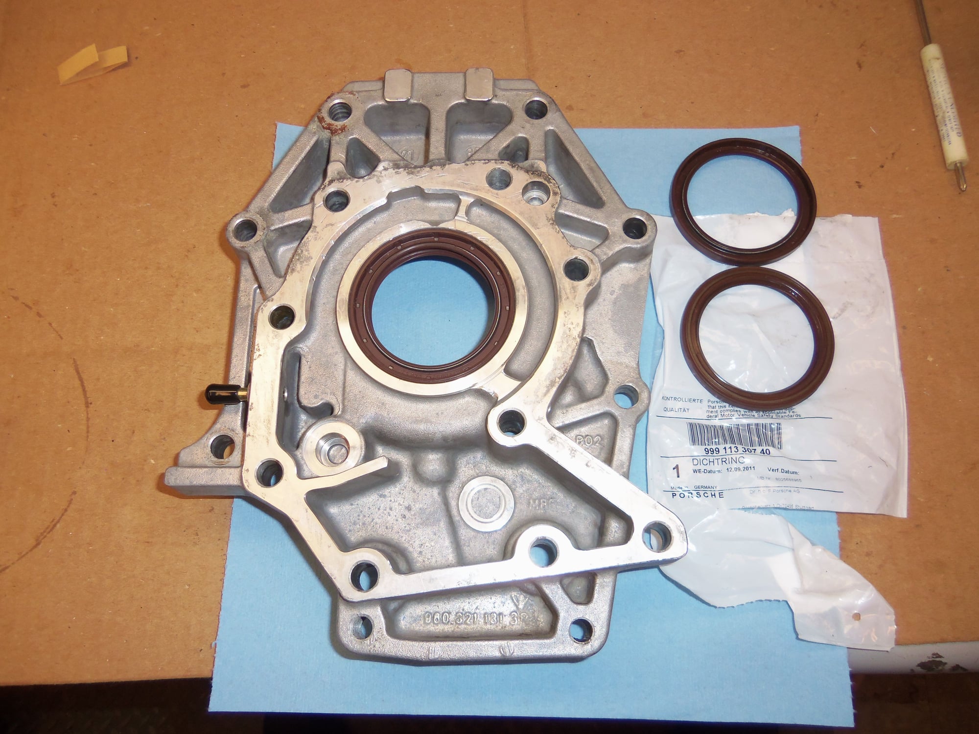
Separator plate with new radial seal installed for transmission side, old seals to the side.
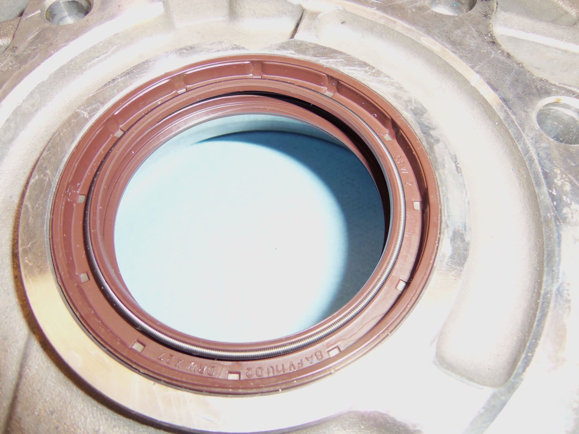
New radial seal installed flush with the surface, lip facing the transmission, just as the old one was installed.
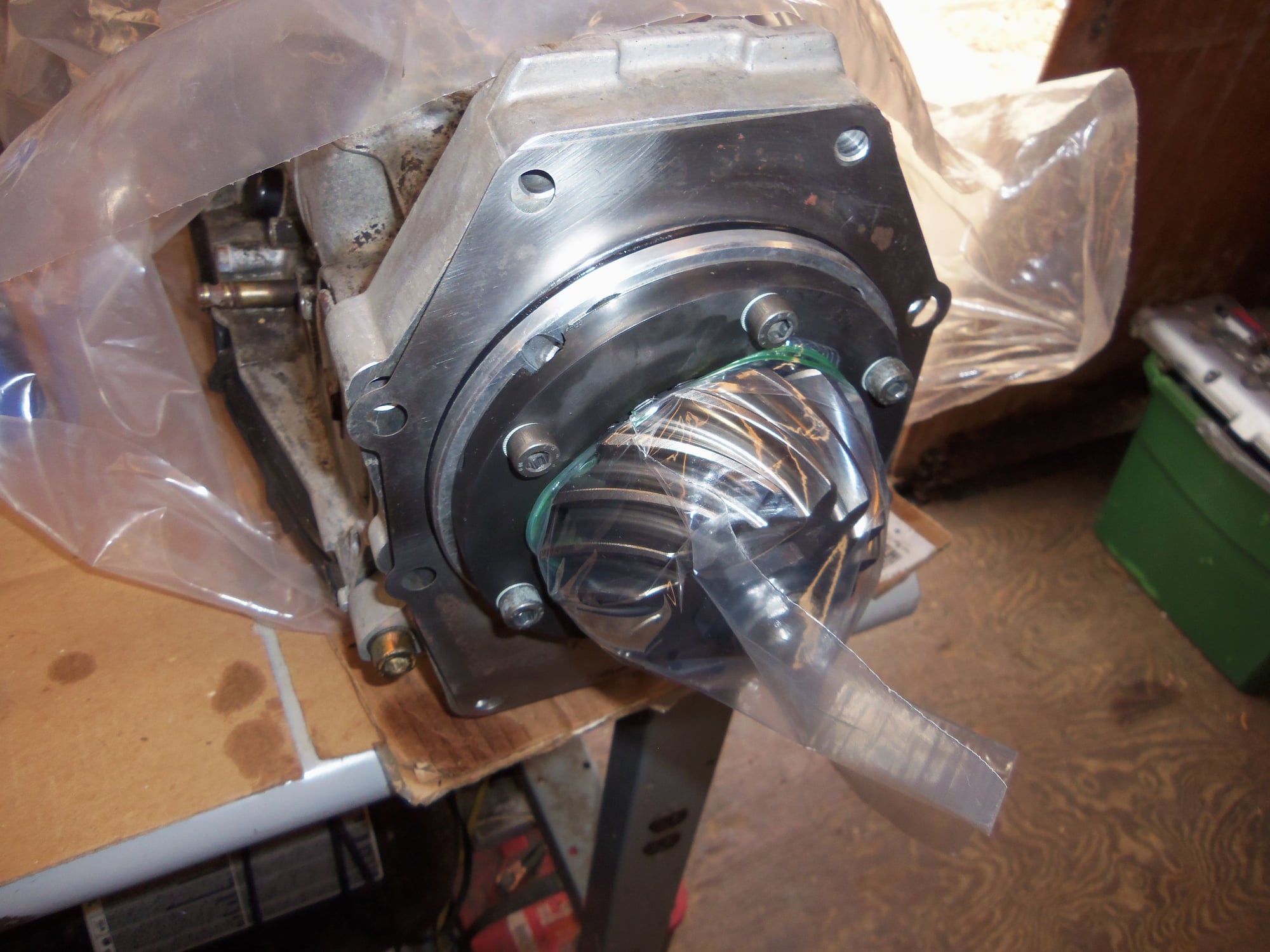
Petroleum jelly liberally applied to both seal lips, as well as inside and out of the machined sealing surface cap for the back side of the pinion gear/bearing assembly. One of my experts suggested inserting the cap into the seals like this, then installing the pinion assembly. Less chance of pushing the springs out of the radial seals.
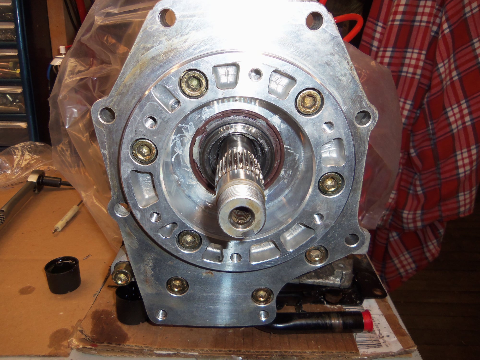
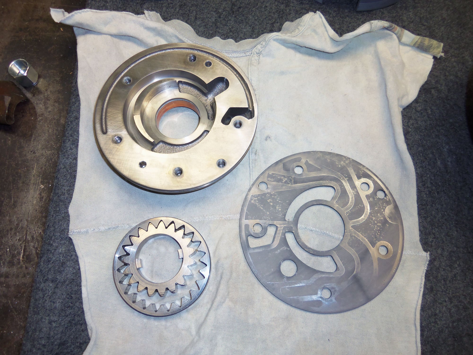
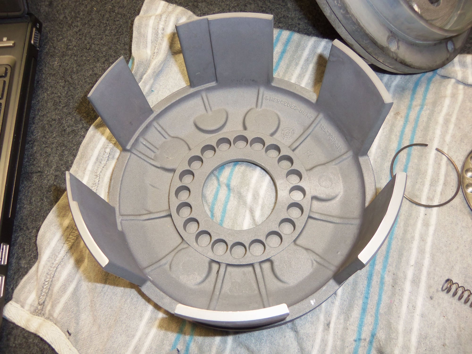
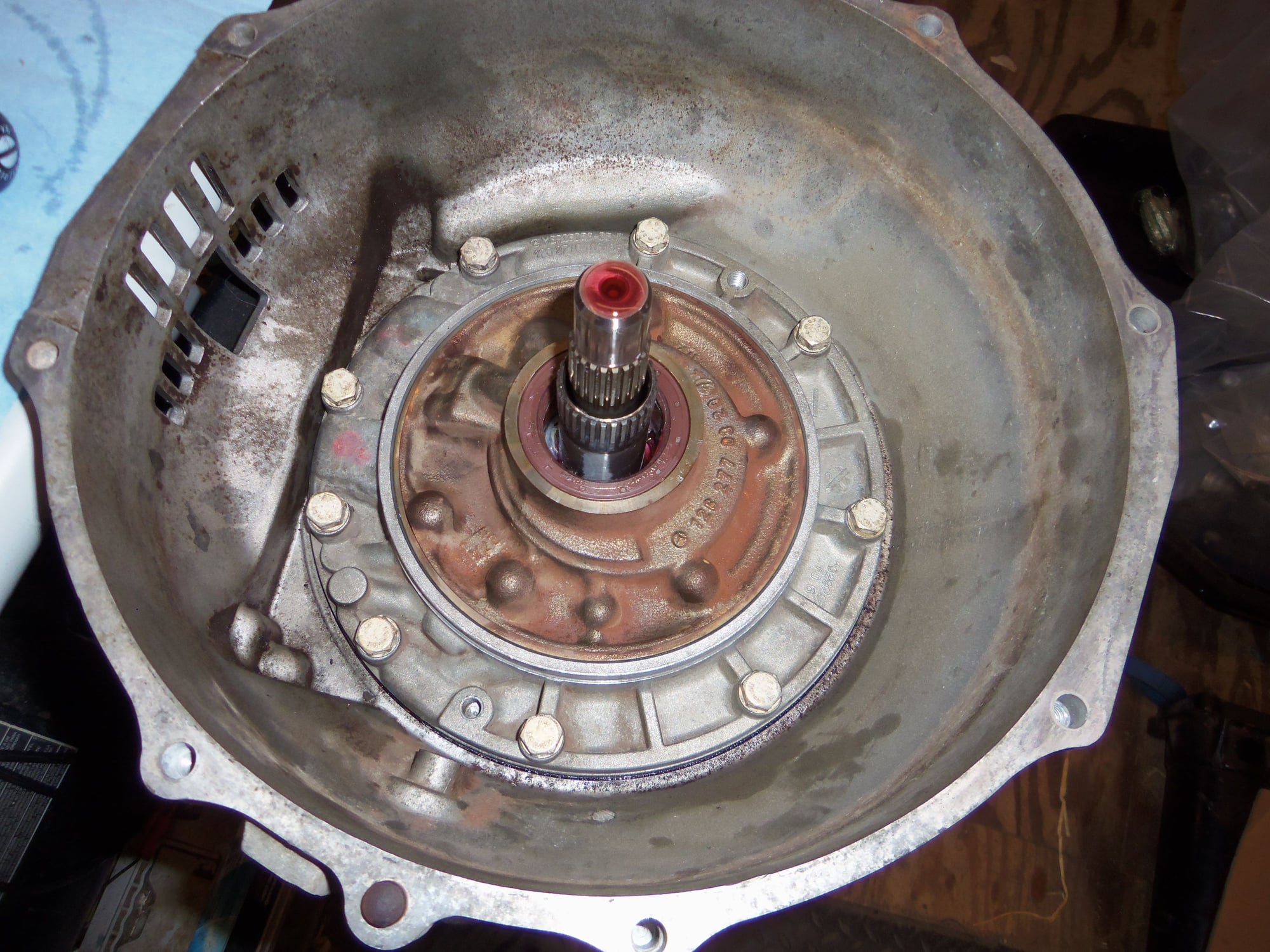
Back end of transmission cleaned and reassembled. All traces of old gasket are gone.
Output shaft is nice and clean.
Everything back where it is supposed to go. Note, all the various things reinstalled here were generously lubricated with fresh ATF.
New gasket for separator plate to transmission, no sealant required.
Separator plate reinstalled back on the end of the transmission. Bolts were lightly coated in silver anti-seize, as it is steel going into aluminum.
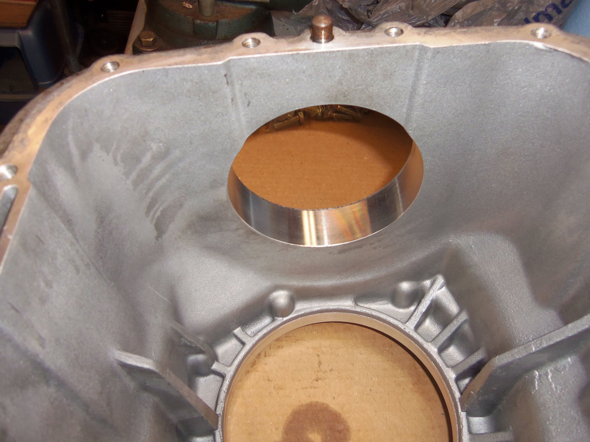
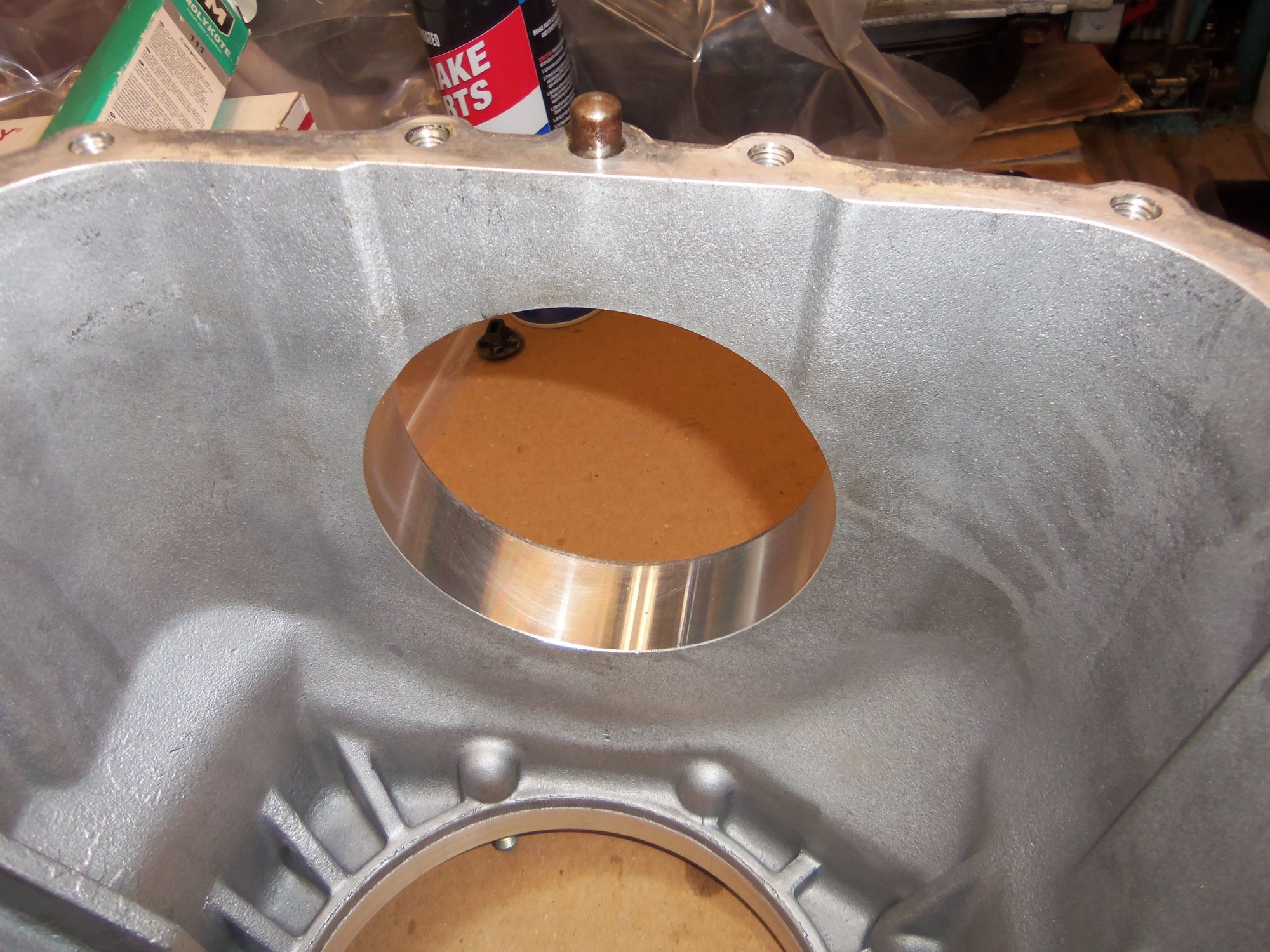
Another view of installed plate, far less crud than before. Also, note the slot in the rib cast into the top of the transmission. This is important in a later photo.
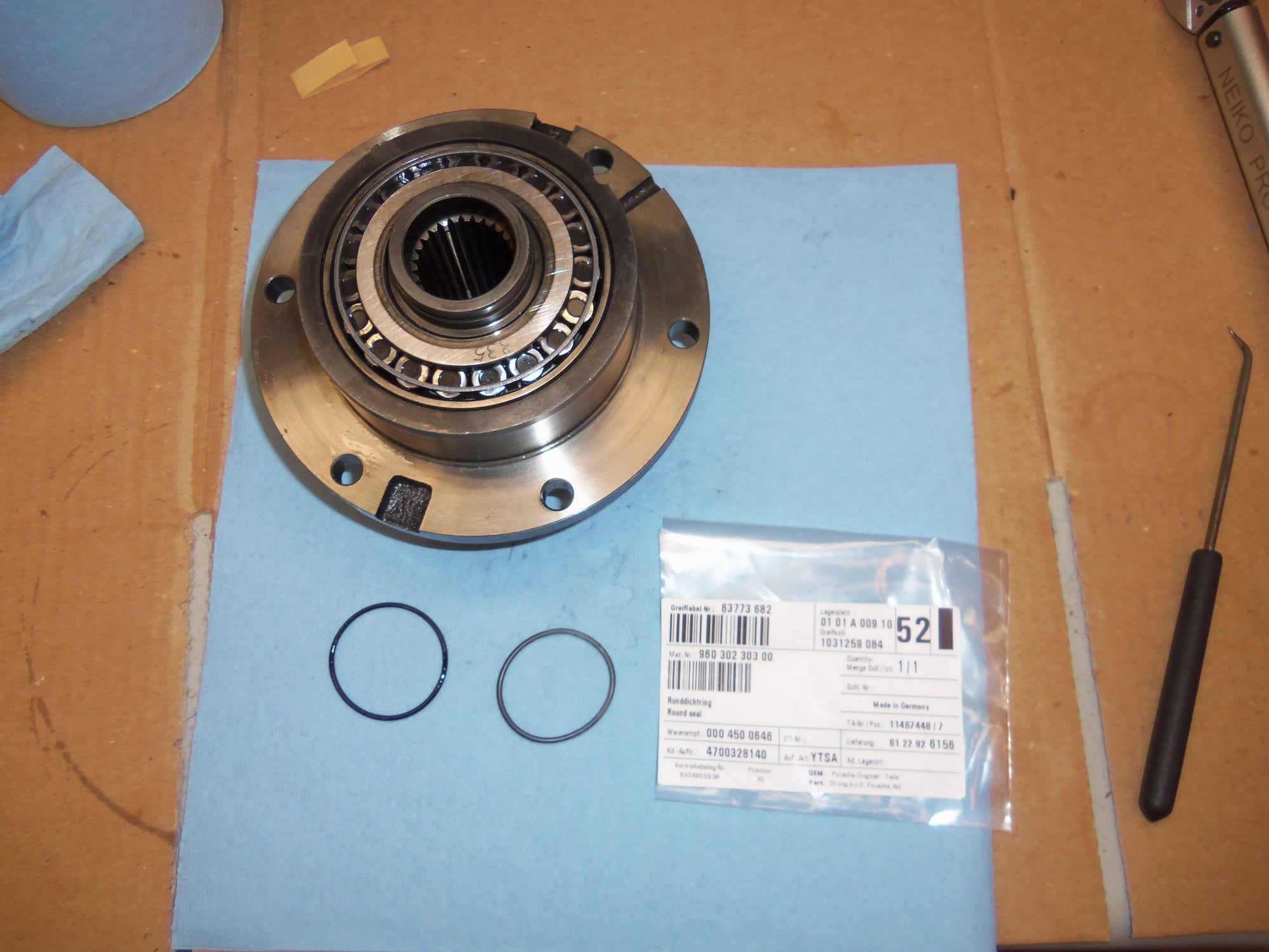
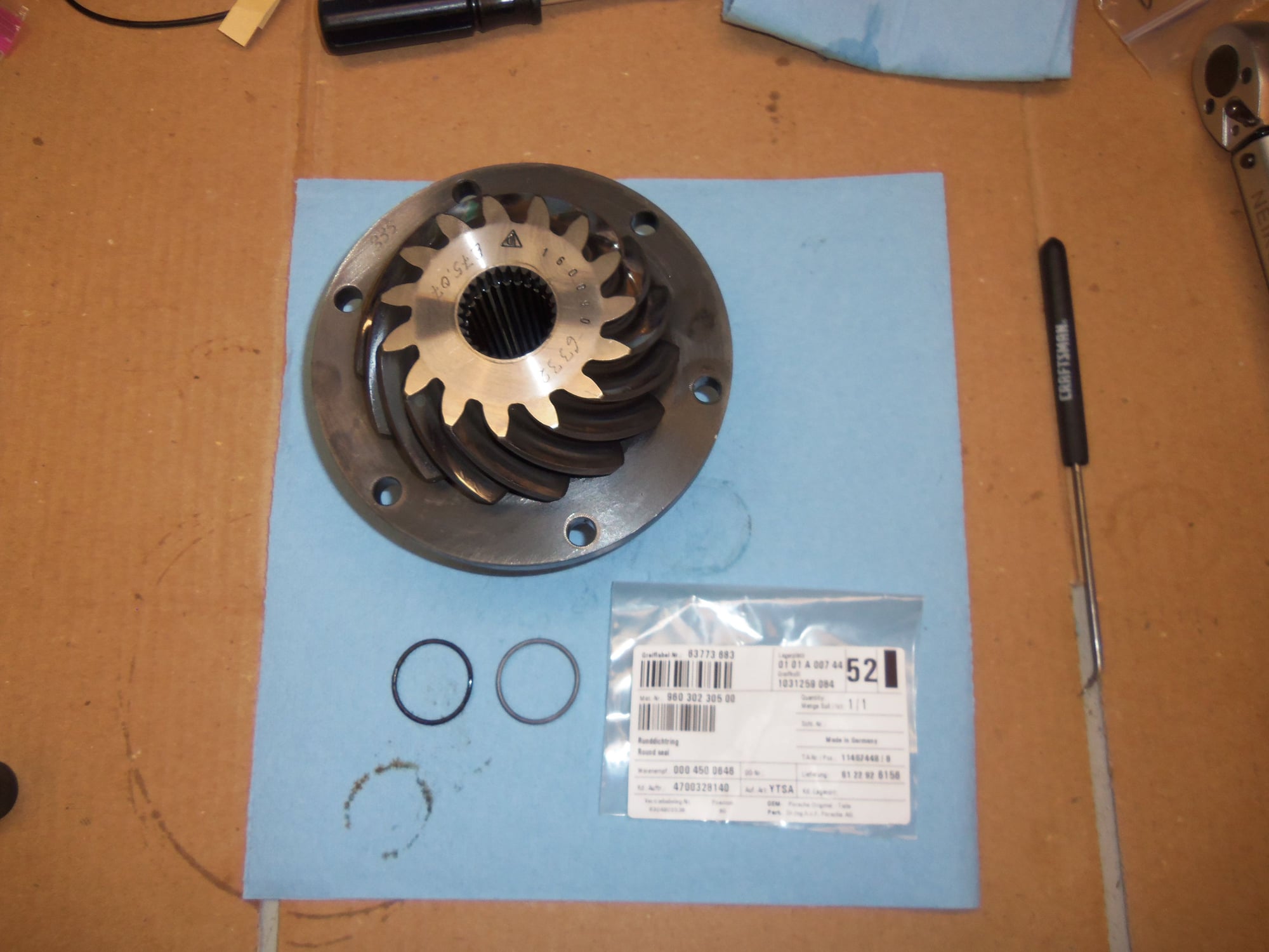
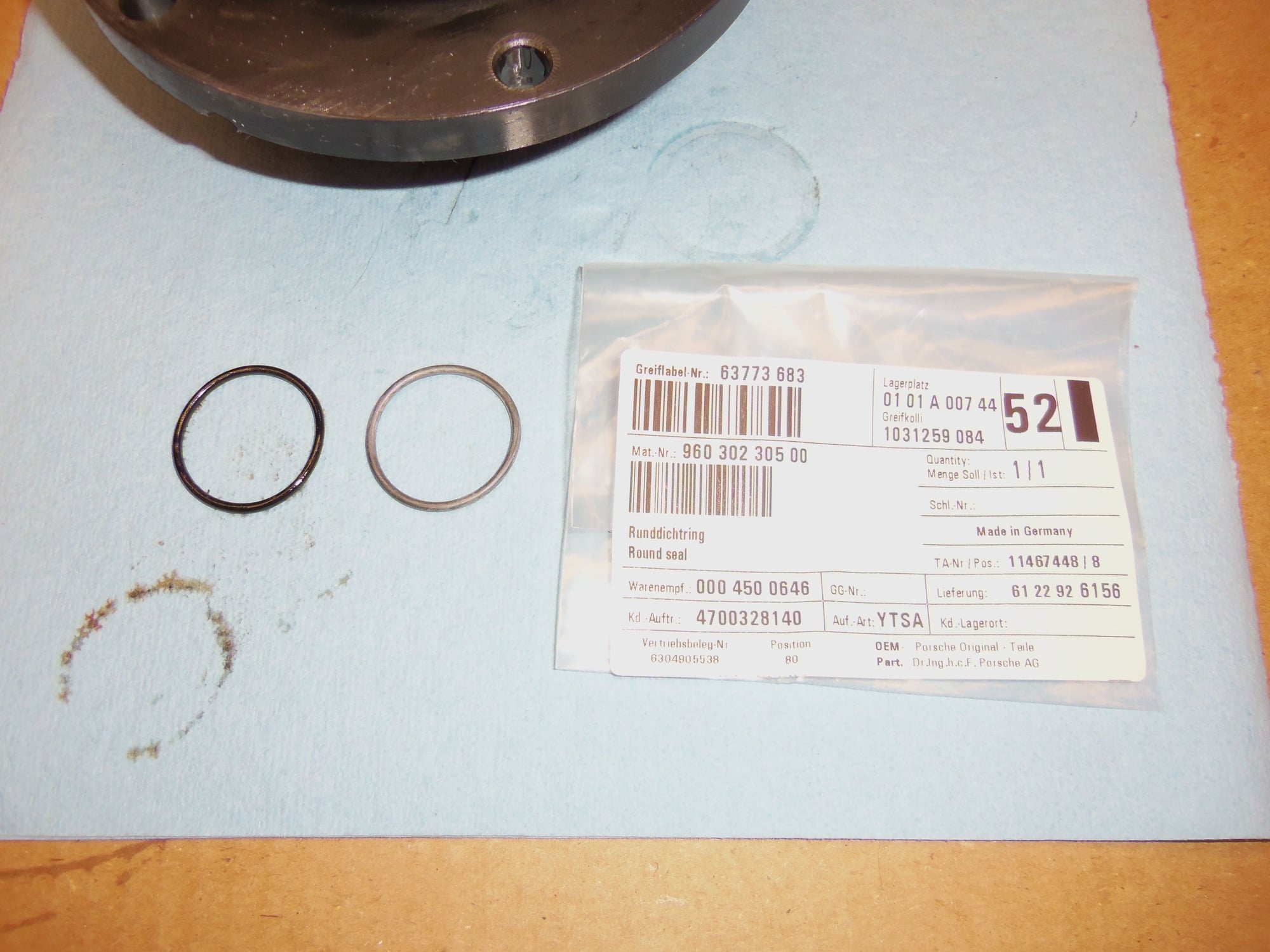
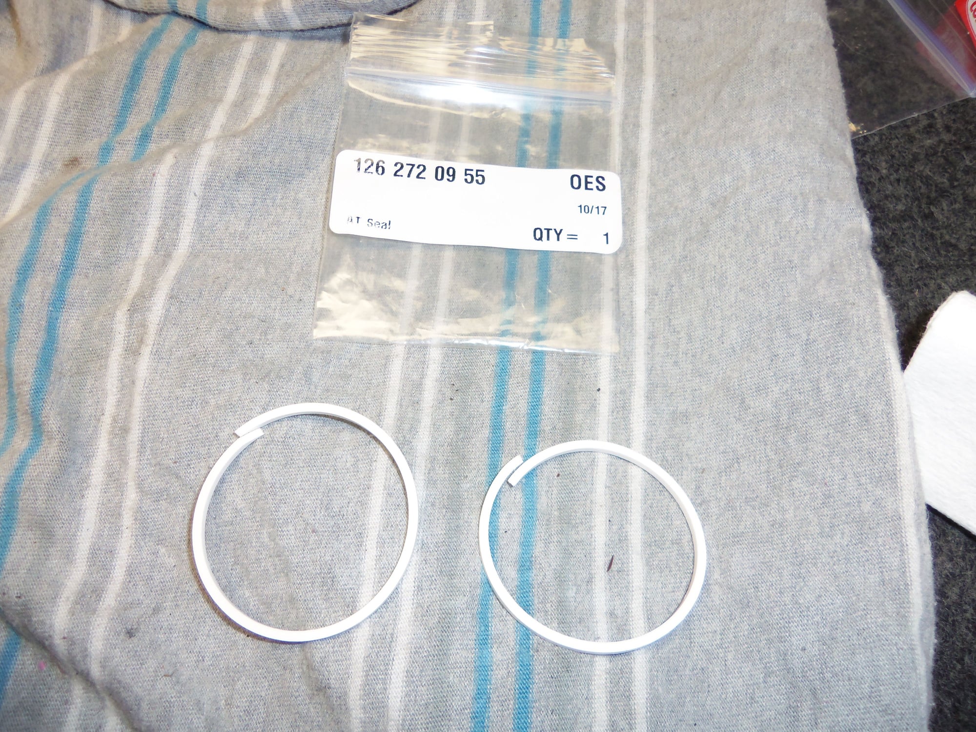
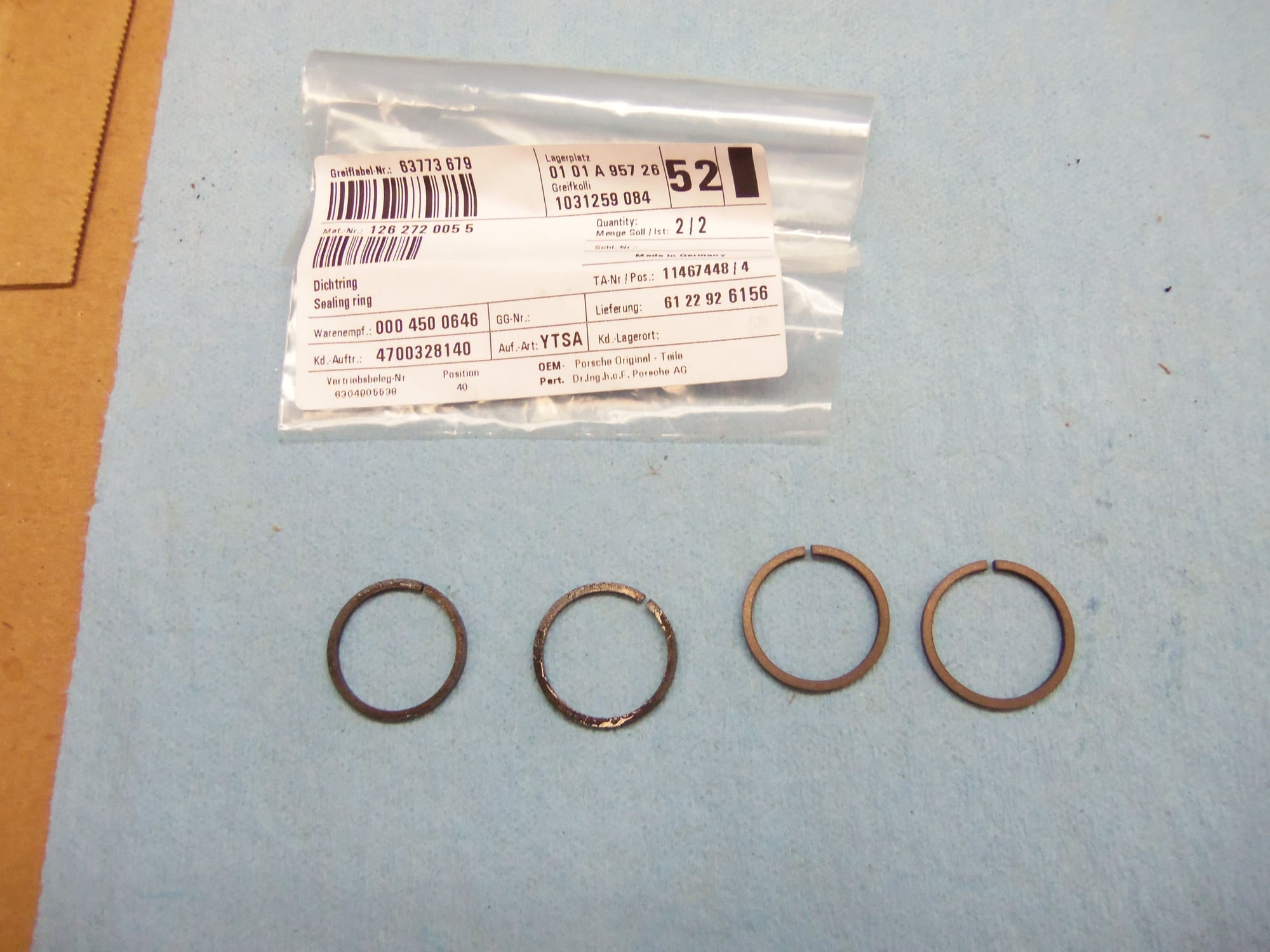
Pinion gear/bearing assembly ready to go back on, new O-ring for sealing the cap at the back. Old O-ring to the left. New O-ring was generously lubricated with petroleum jelly.
Better view of the O-ring part number.
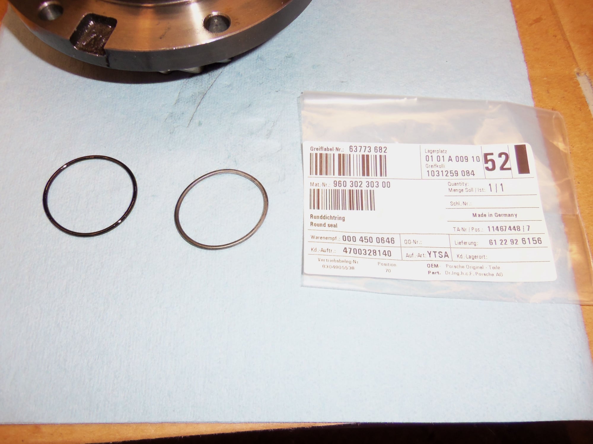
Front side of the pinion gear with the mystery O-ring that I initially could not find. New O-ring at the right, old at the left.
Better view of the O-ring part number.
Screenshot of PET for the differential on the A28/07. Note item 6a. I could not find it for the life of me on the pinion gear.
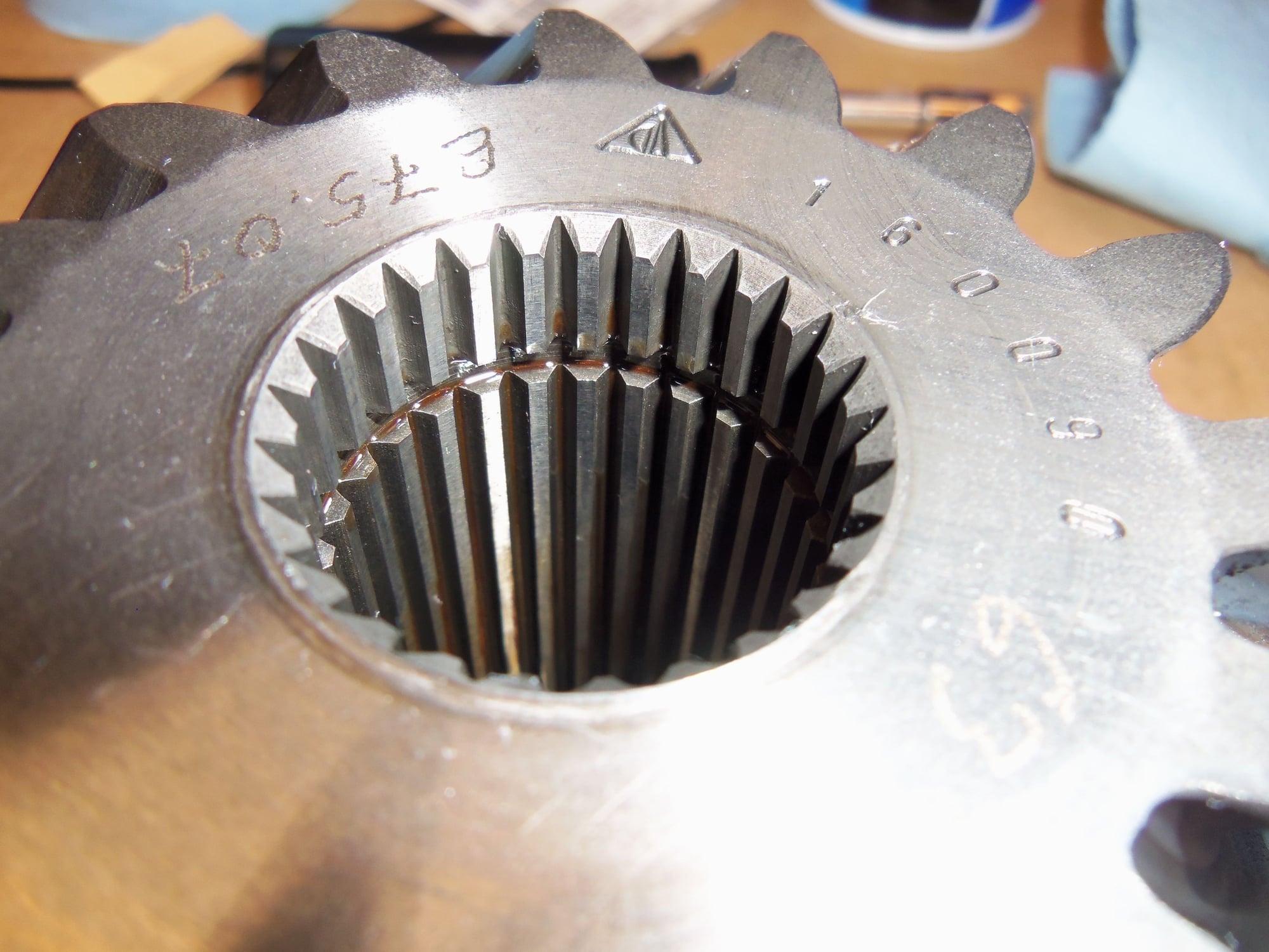
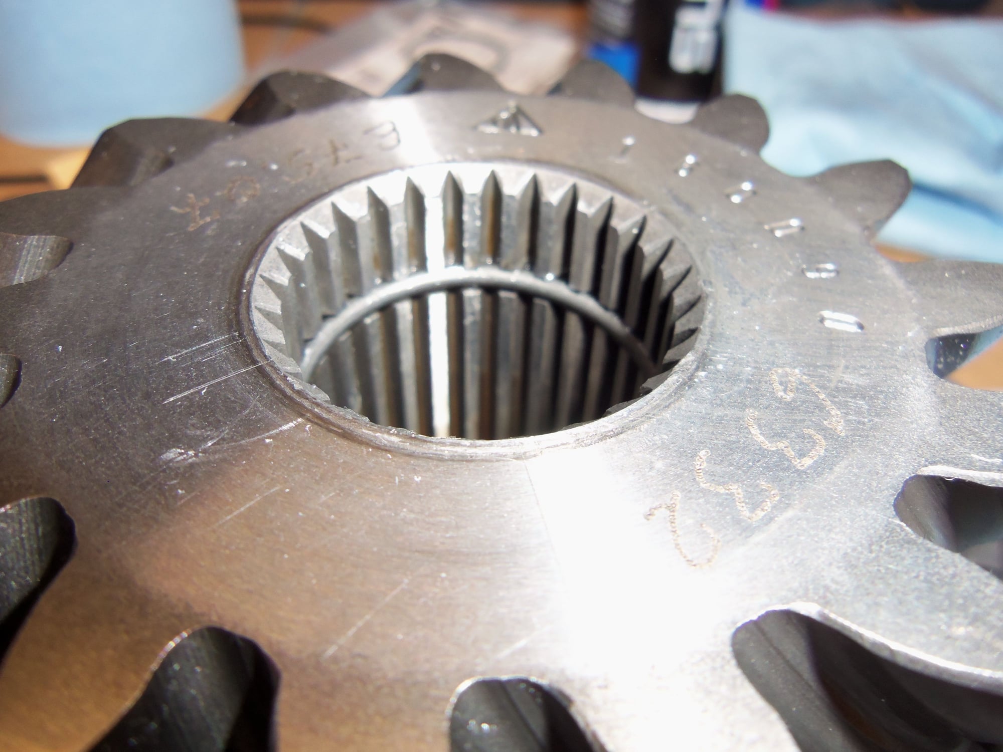
One of my experts explained to me that the O-ring was INSIDE the center of the pinion gear. Oh... Note the groove in the splines.
New O-ring installed. It was generously lubricated with petroleum jelly at installation. As well, the entire splined area on both sides of the O-ring was coated with petroluem jelly. As was the splines on the output shaft. The same expert who told me about the O-ring explained that it is very easy to cut this O-ring by careless installation of the pinion assembly. Hence the overuse of lube on my part. As well as GENTLY pushing the pinion assembly onto the output shaft. Here's hoping it worked!!!
Pinion assembly retaining nut torqued to 280 ft/lbs. I had a prybar into the slot in the rib on the top of the back of the transmission casing, with the cheater pipe bucked up on my shoulder. It was a b*tch, but not as bad as I expected. Meaning I expected to turn the transmission over into the floor...
Very NOT elegant displacing of the pinion nut collar into the keyway on the output shaft. But, it will work.
Another view of my shame.
Pinion assembly is now installed!
Yes, the shim was installed. The pinion assembly mounting bolts were lightly coated in silver anti-seize for going into the aluminum separator plate.
With the pinion assembly reinstalled, I could move onto reinstalling the differential casing. That has been the main goal. I need to stand this transmission on its end to properly install the front pump and torque converter. So...I need the differential casing and its rear cover.
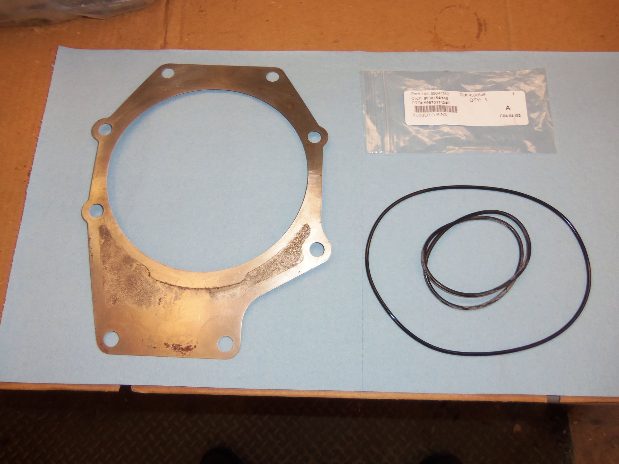
Installation was straight forward. Its just a shim, O-ring seal, held on by bolts & nuts.
Cleaned shim and O-ring seal for the register on the separator plate. New O-ring is coiled up inside old one.
New O-ring generously lubricated with Dow 111 and installed in the groove on the register on the separator plate, behind the pinion assembly.
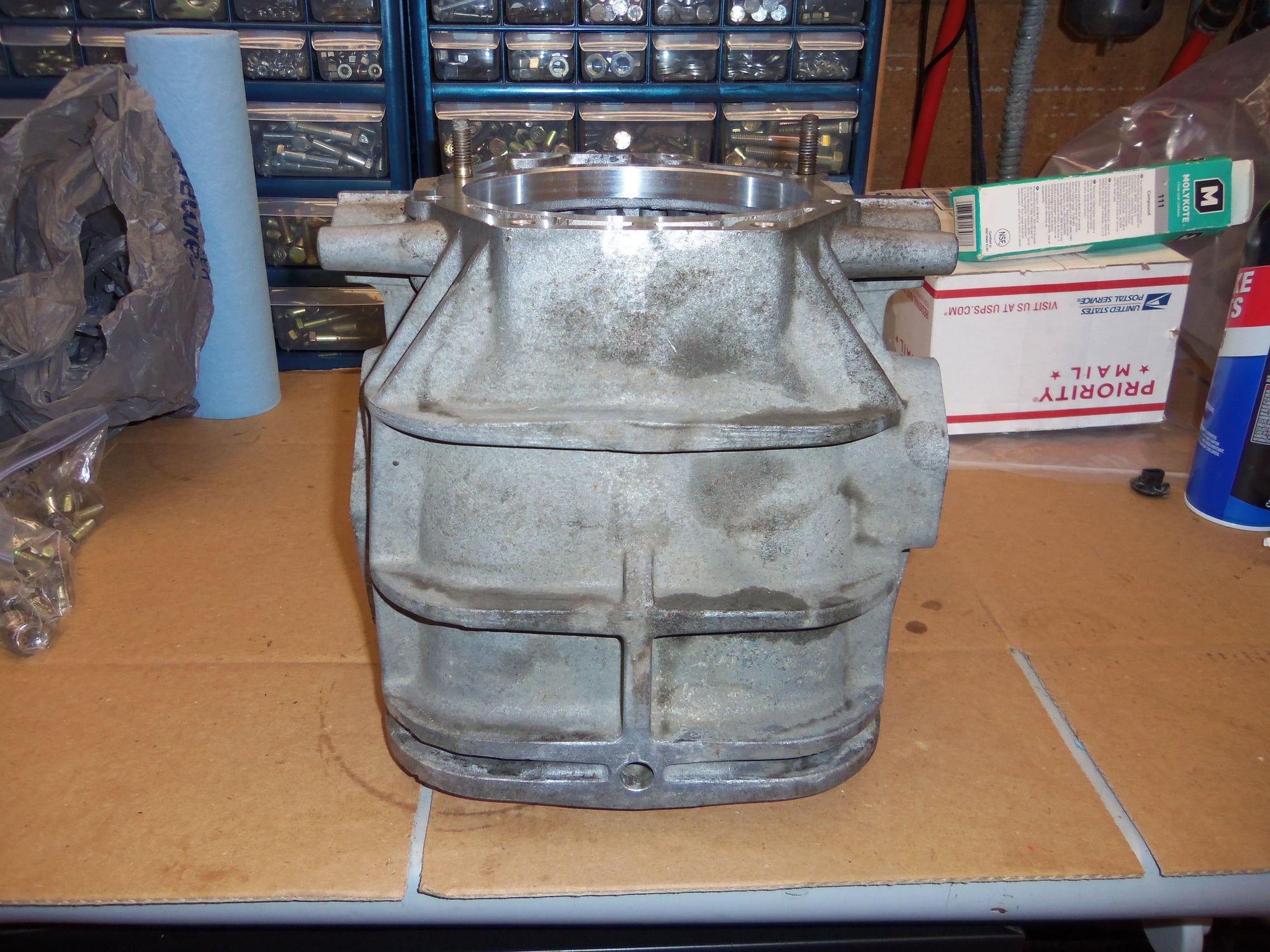
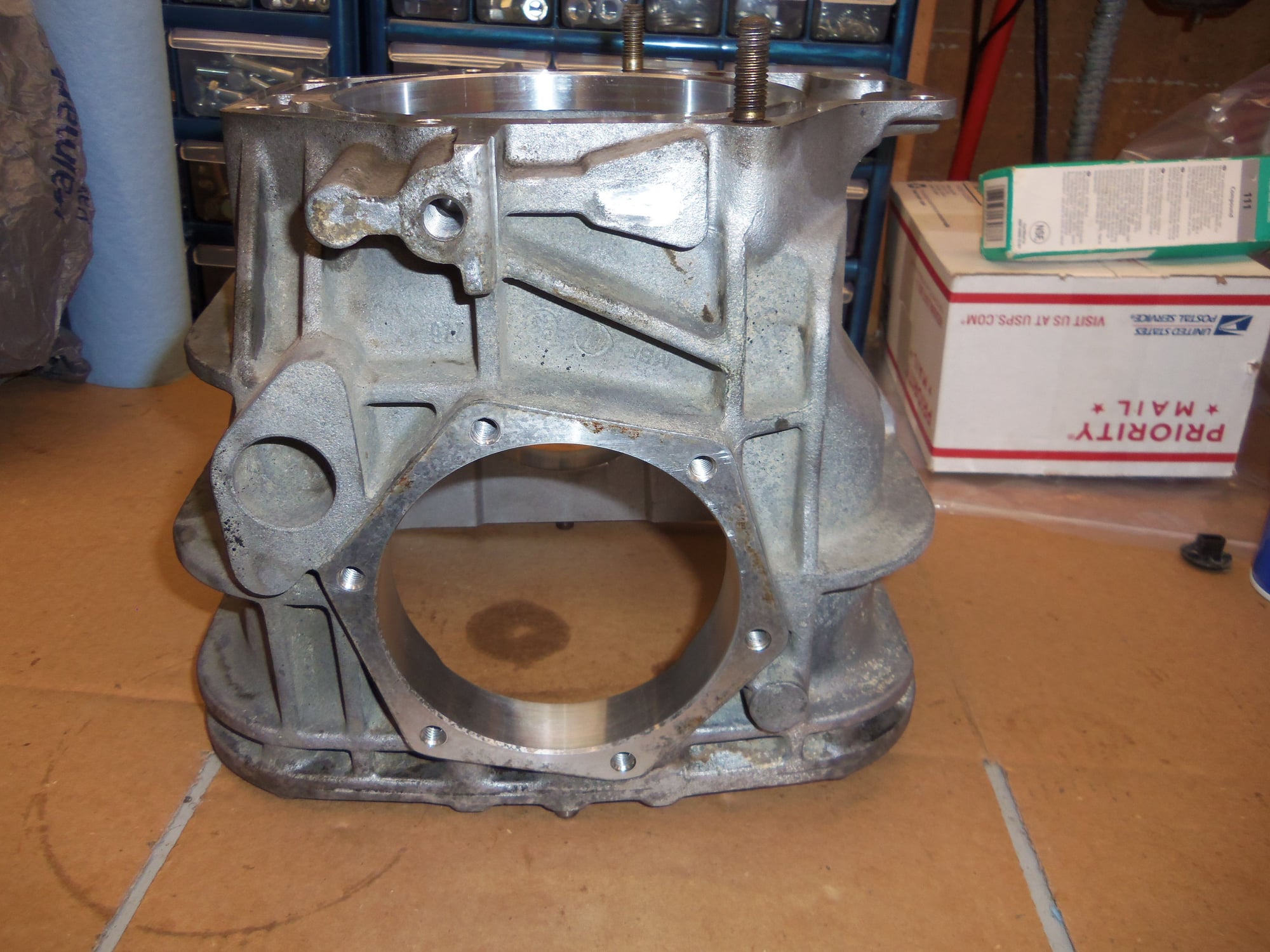
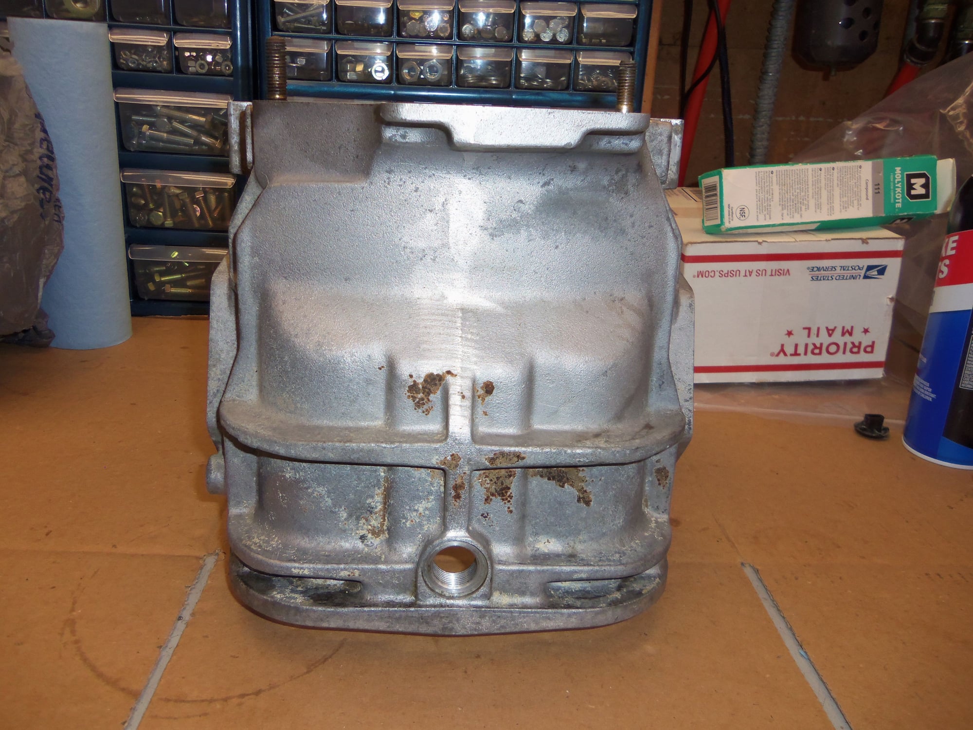
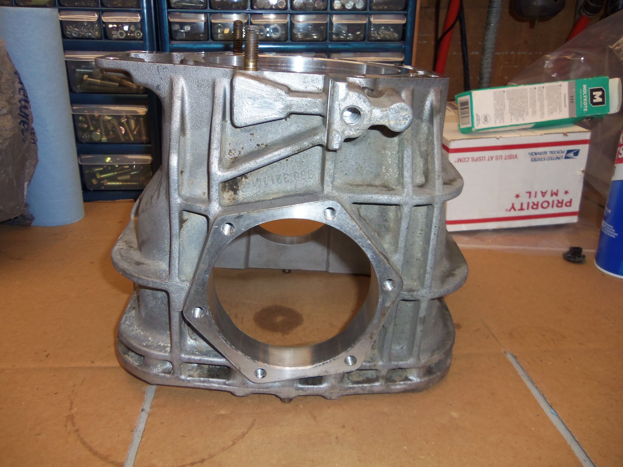
Cleaned differential casing.
Mating surface scraped clean with razor blades.
All bolt holes and studs cleaned with thread chasers.
There is still a little hard baked on crud.
Inside of the casing is clean as a whistle.
Scrub, rinse with brake cleaner, blow out with air. Repeat as necessary. Do it one more time just because.
Clean.
Clean.
Clean.
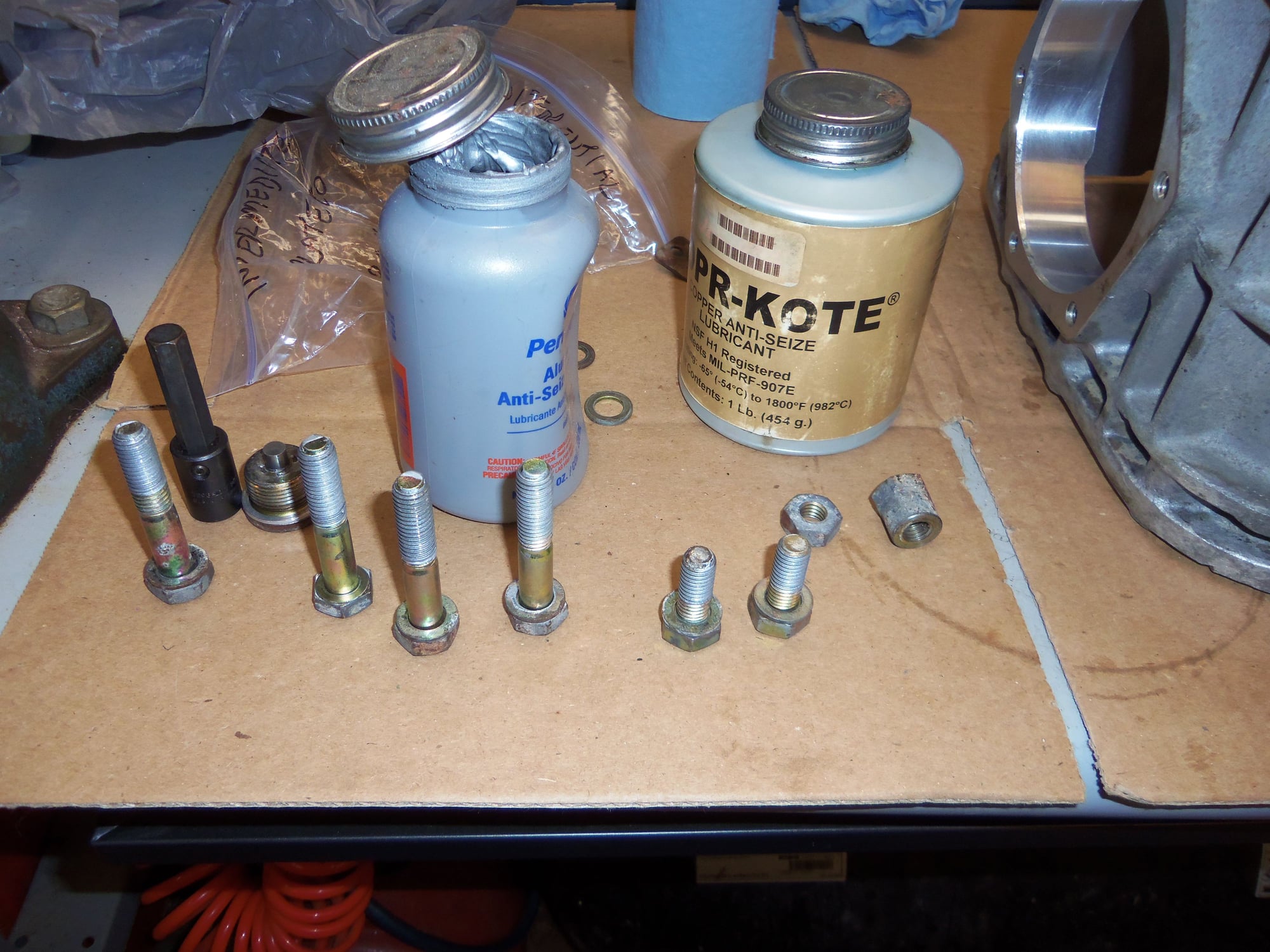
Bolts that threaded into the differential casing were lightly coated with silver anti-seize. The studs were lightly coated with copper anti-seize.
The bore for the sealing O-ring was generously lubricated with Dow 111.
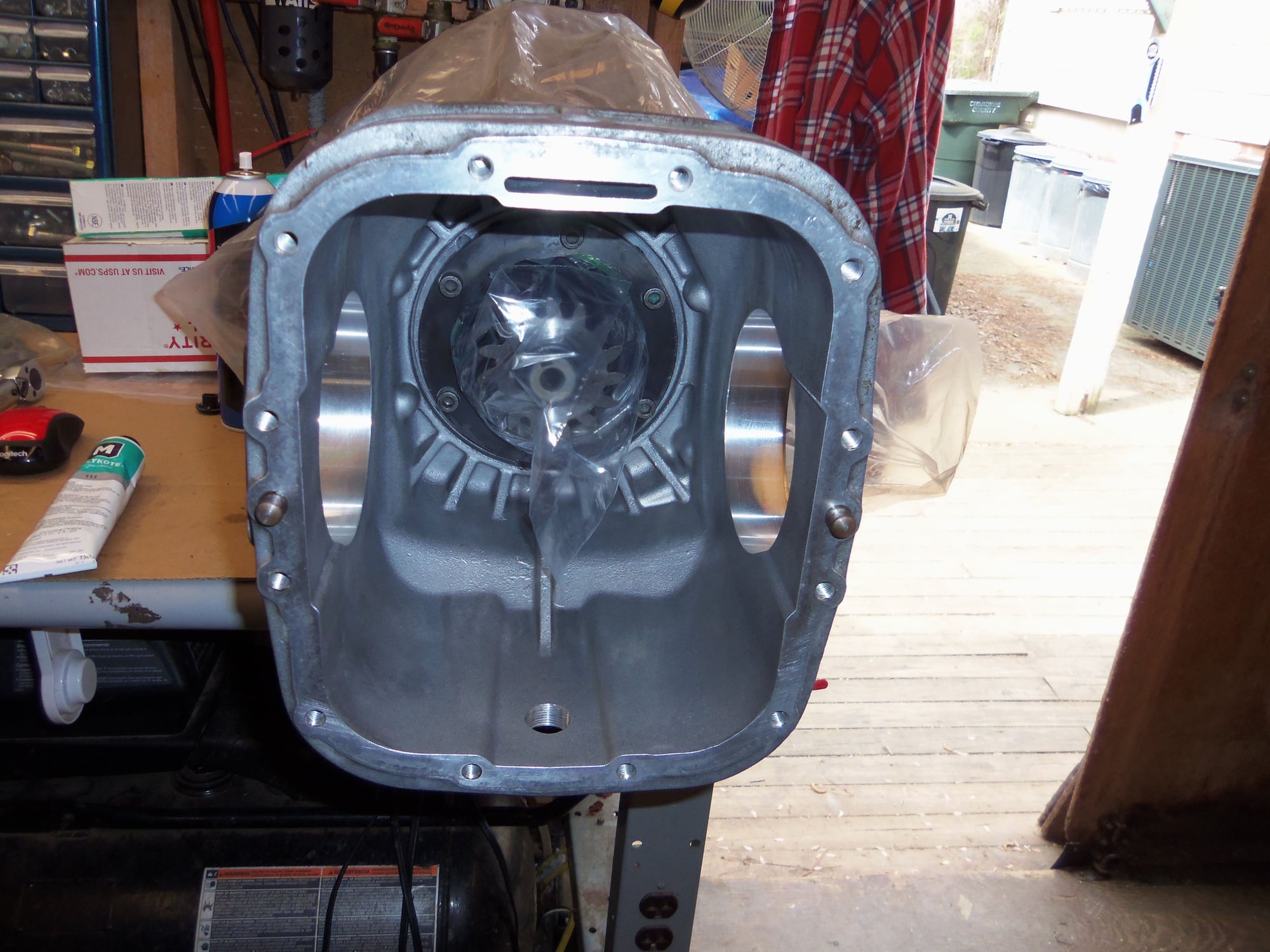
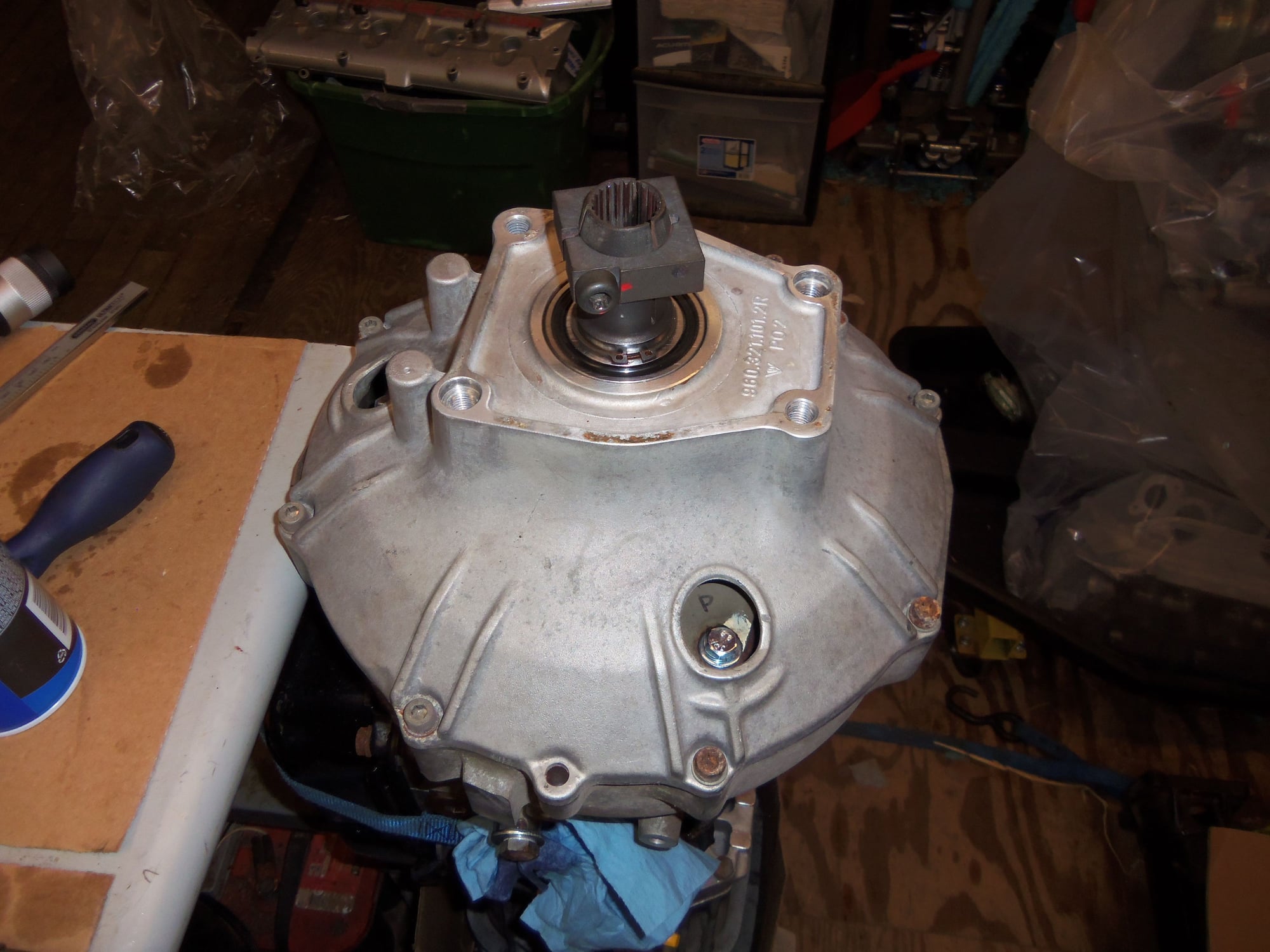
Differential casing securely mounted back onto the transmission.
I remembered to put the wiring harness clip tab back under the bolt.
Could not get a torque wrench on this barrel nut. So, I used a crow's foot and adjusted the torque.
Same for this nut.
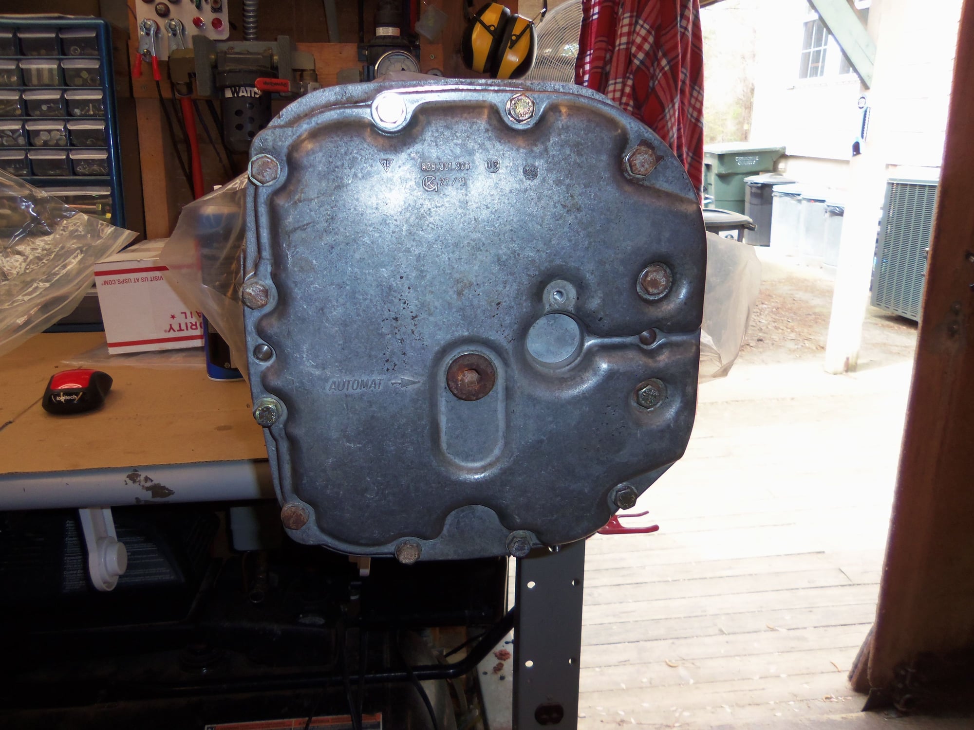
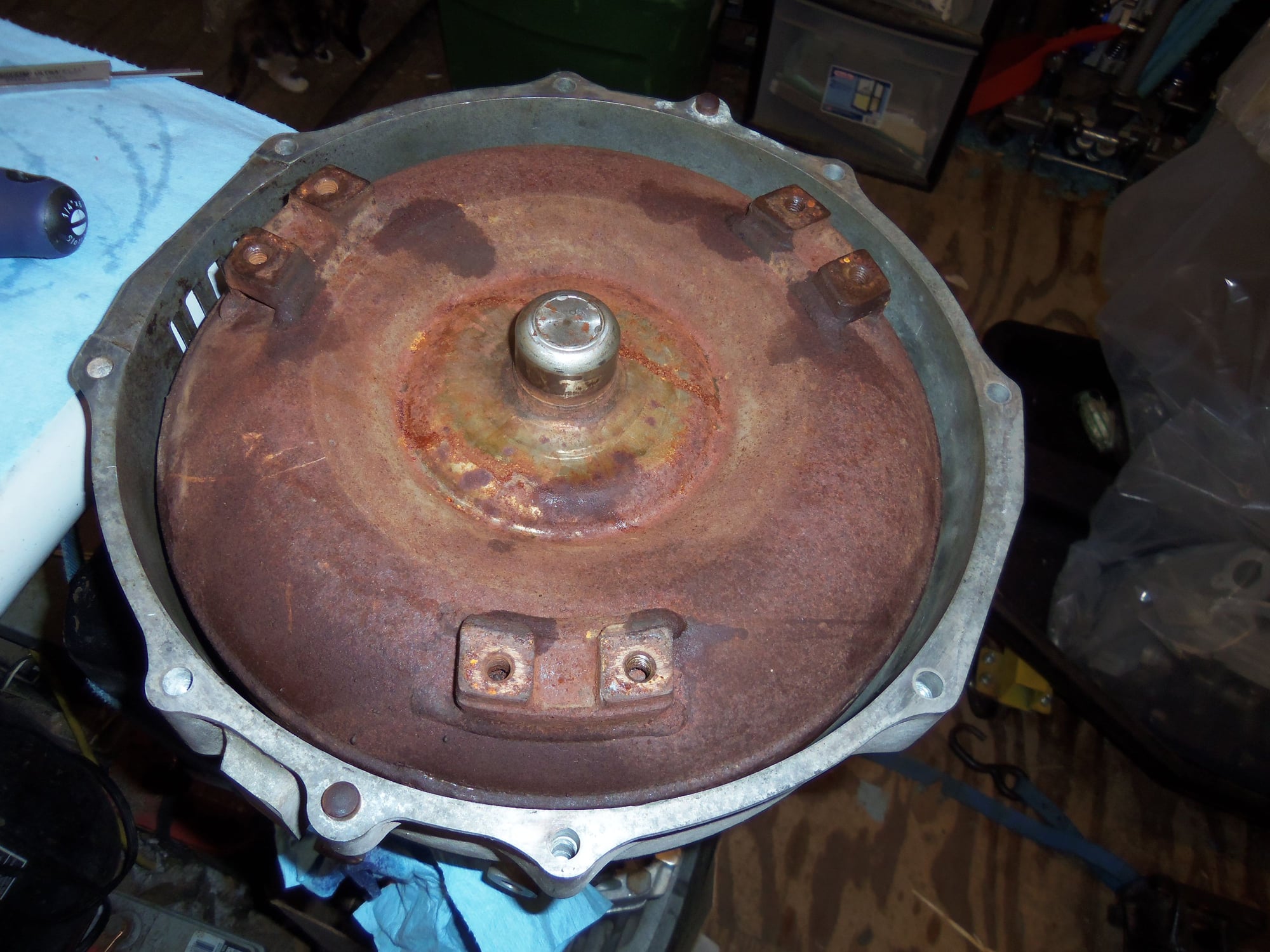
Cover has been reinstalled with no gasket, bolts are dry and hand tight. I just wanted to provide a good mounting surface to sit the transmission down on. Did not want to damage the cover gasket sealing surface or the two locating dowel pins.
Thank you, sir! This is the only way I know how to do stuff like this. I am just as bad with my garden tractors.
Inch by inch, sorry, millimeter by millimeter, piece by piece, I am getting the Red Witch back together.
Now, onto the whole point of this relative fiasco: reinstalling the transmission front pump. As I learned AFTER I removed the front pump, it MUST be installed vertically. So, after reinstalling the differential casing and rear cover, I could now set the transmission up vertically.
I reassembled the front pump after meticulous cleaning and replacement of all seals. Everything that moved was generously lubricated with petroleum jelly.
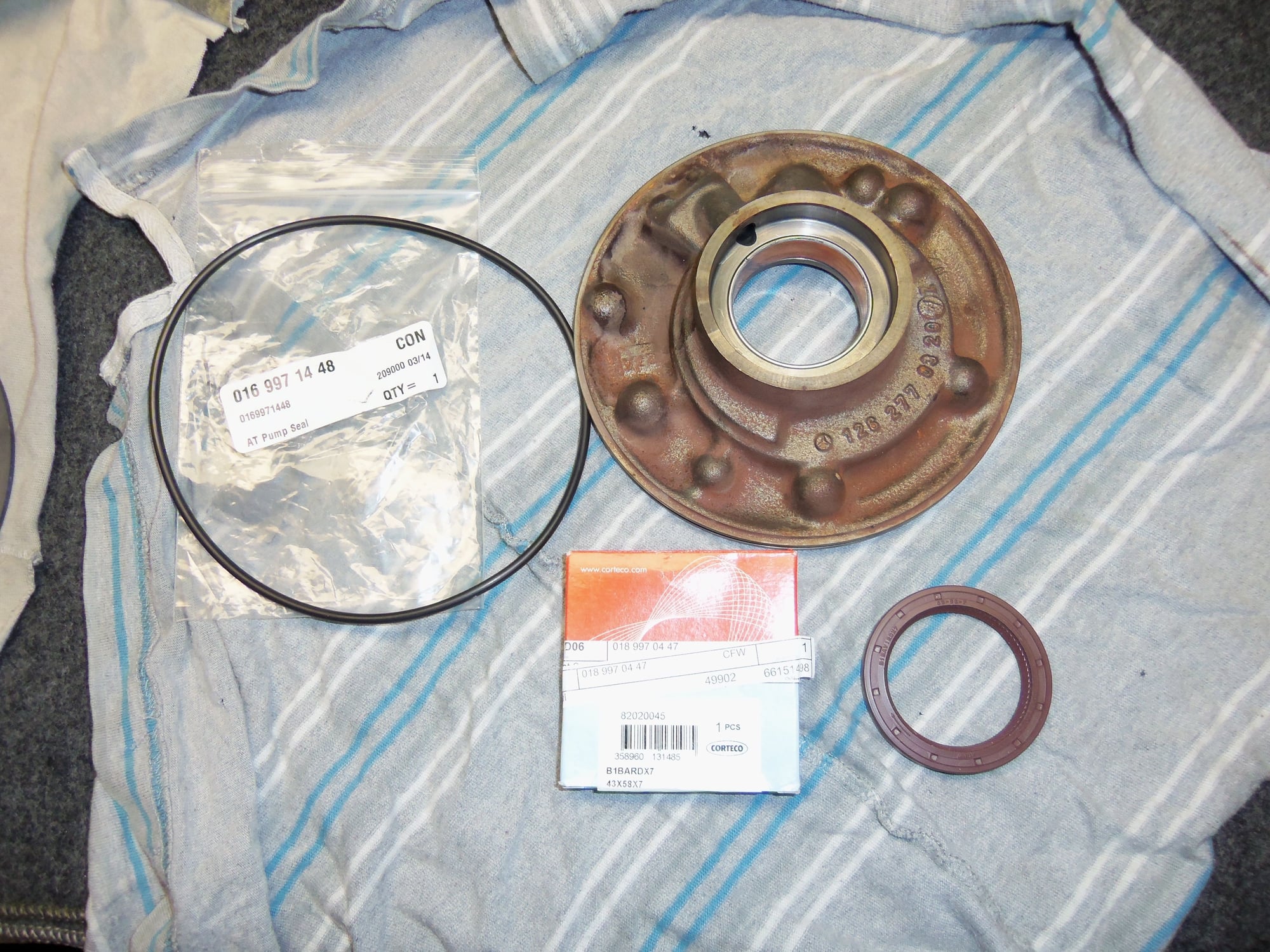
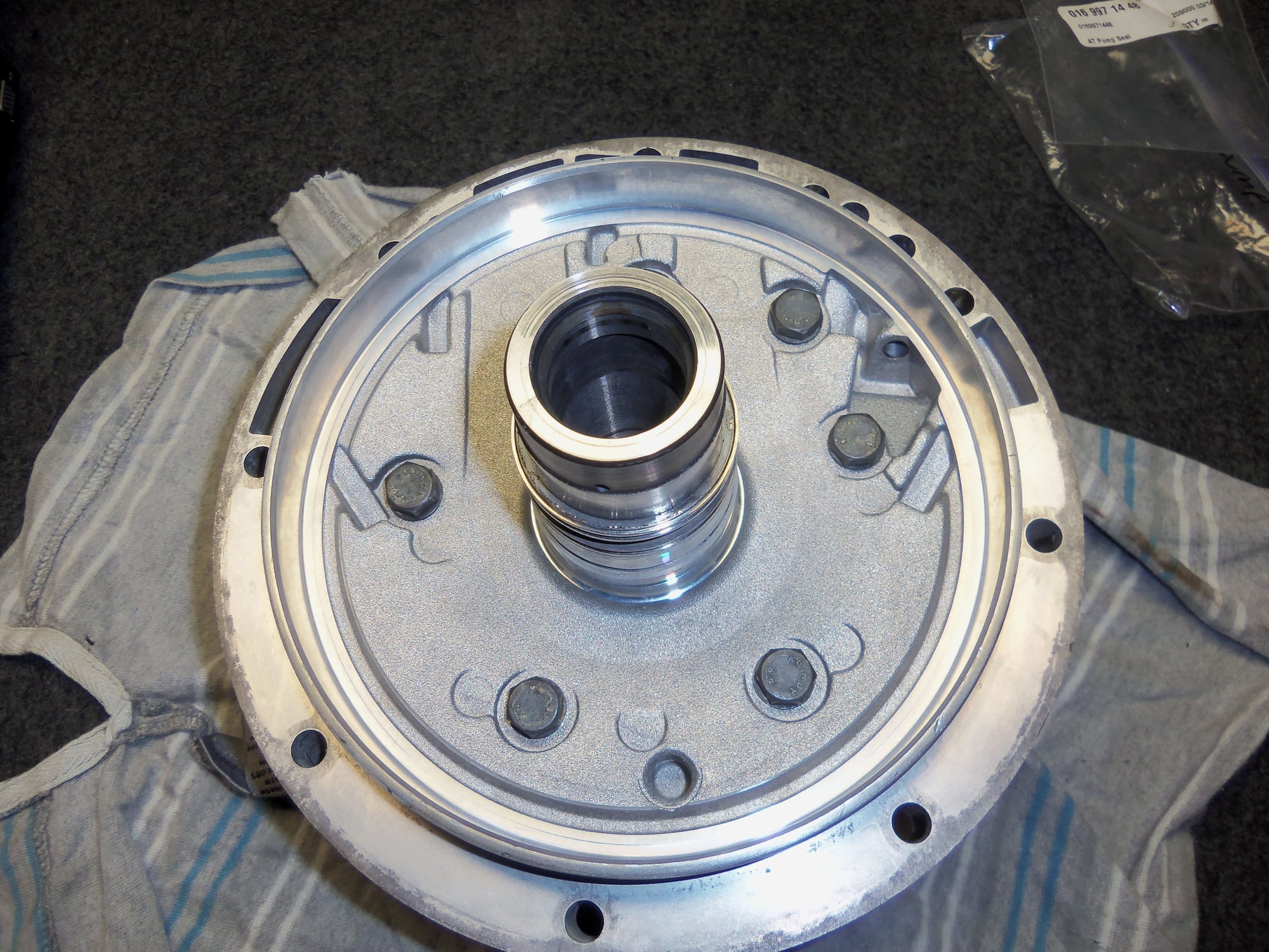
Front pump cover, cleaned and ready to go.
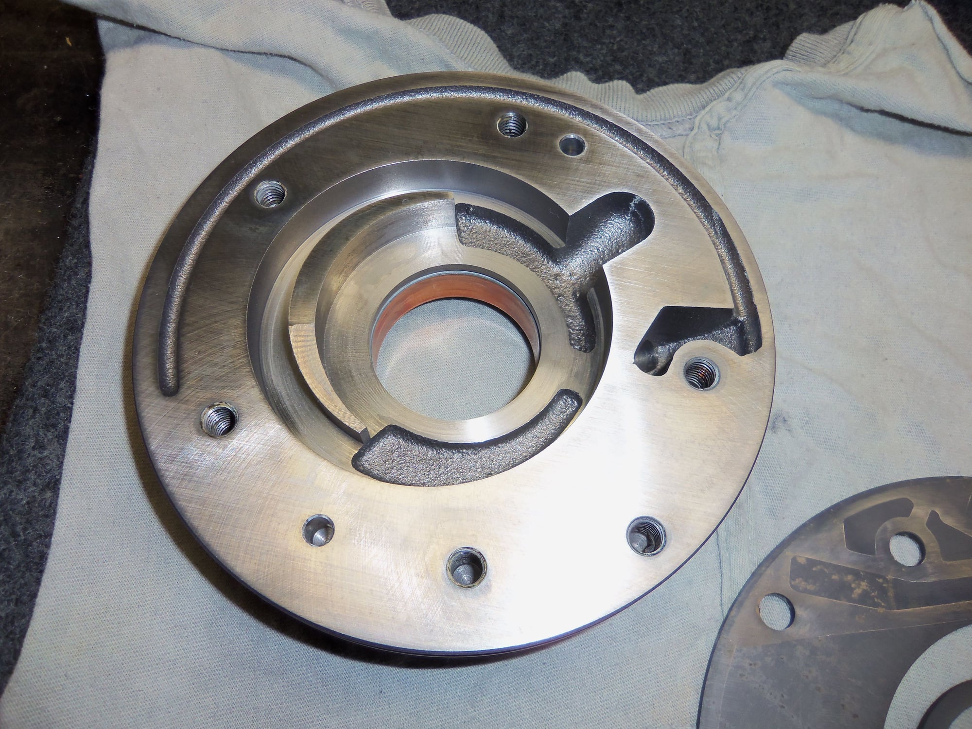
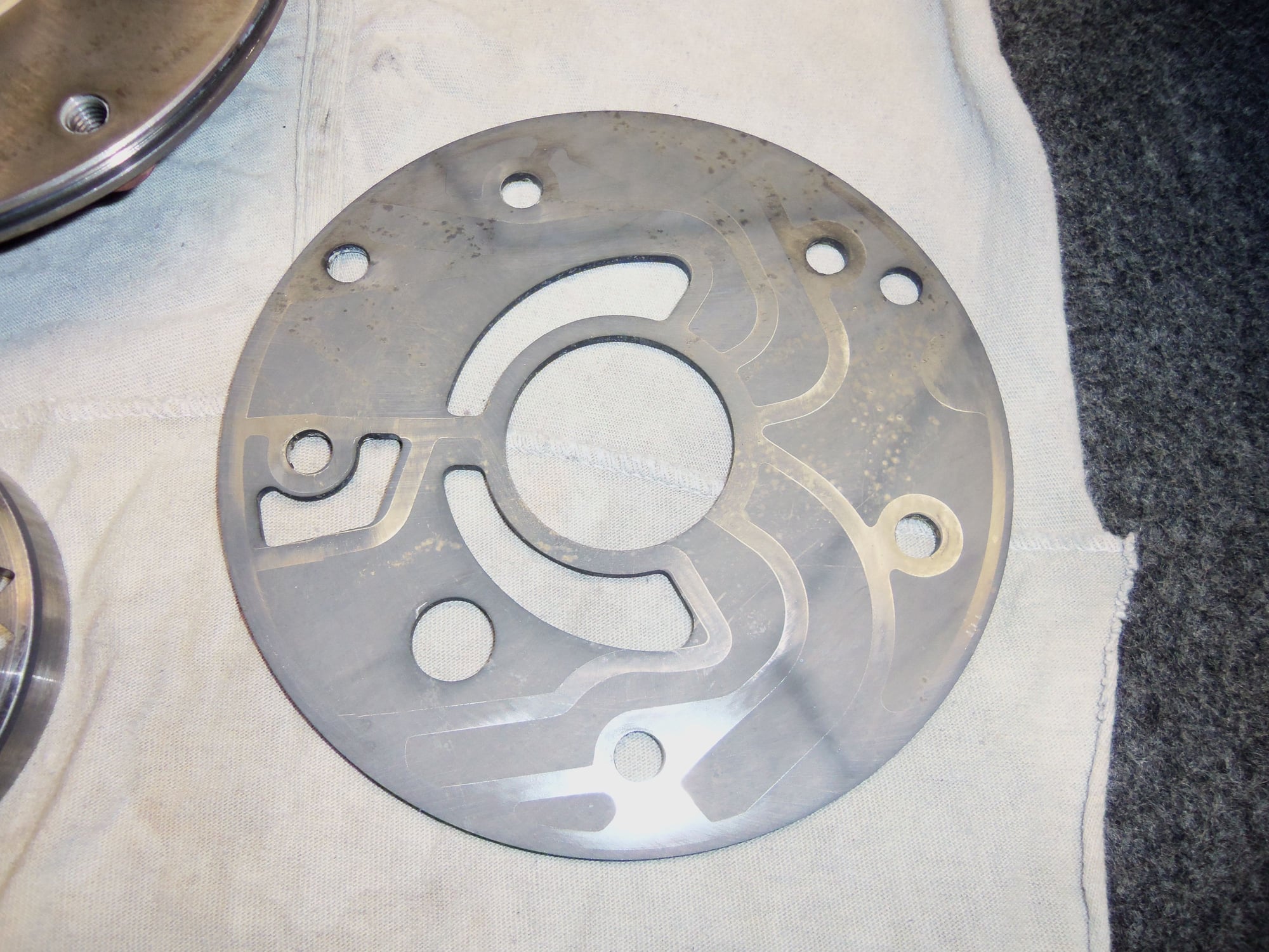
Front pump assembly and separator plate.
Back sides of front pump assembly and separator plate.
Bushing is in acceptable condition.
All threaded holes have been chased and cleaned.
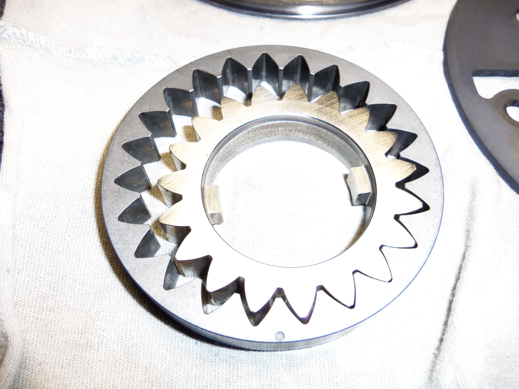
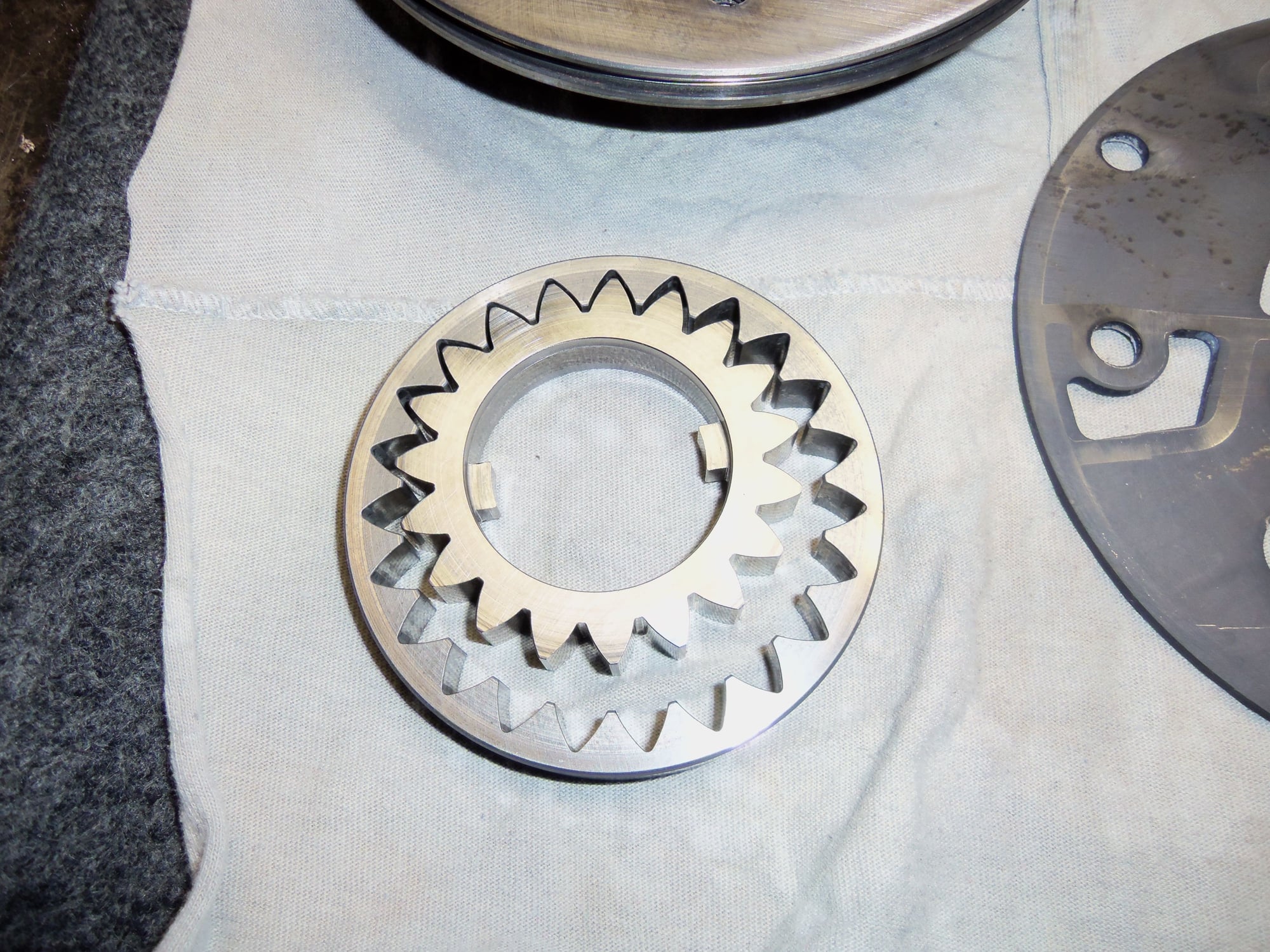
Pump gears. Note the ID dot on the outer gear.
Back side of pump gears. Note matching radial wear marks on inner and outer gears.
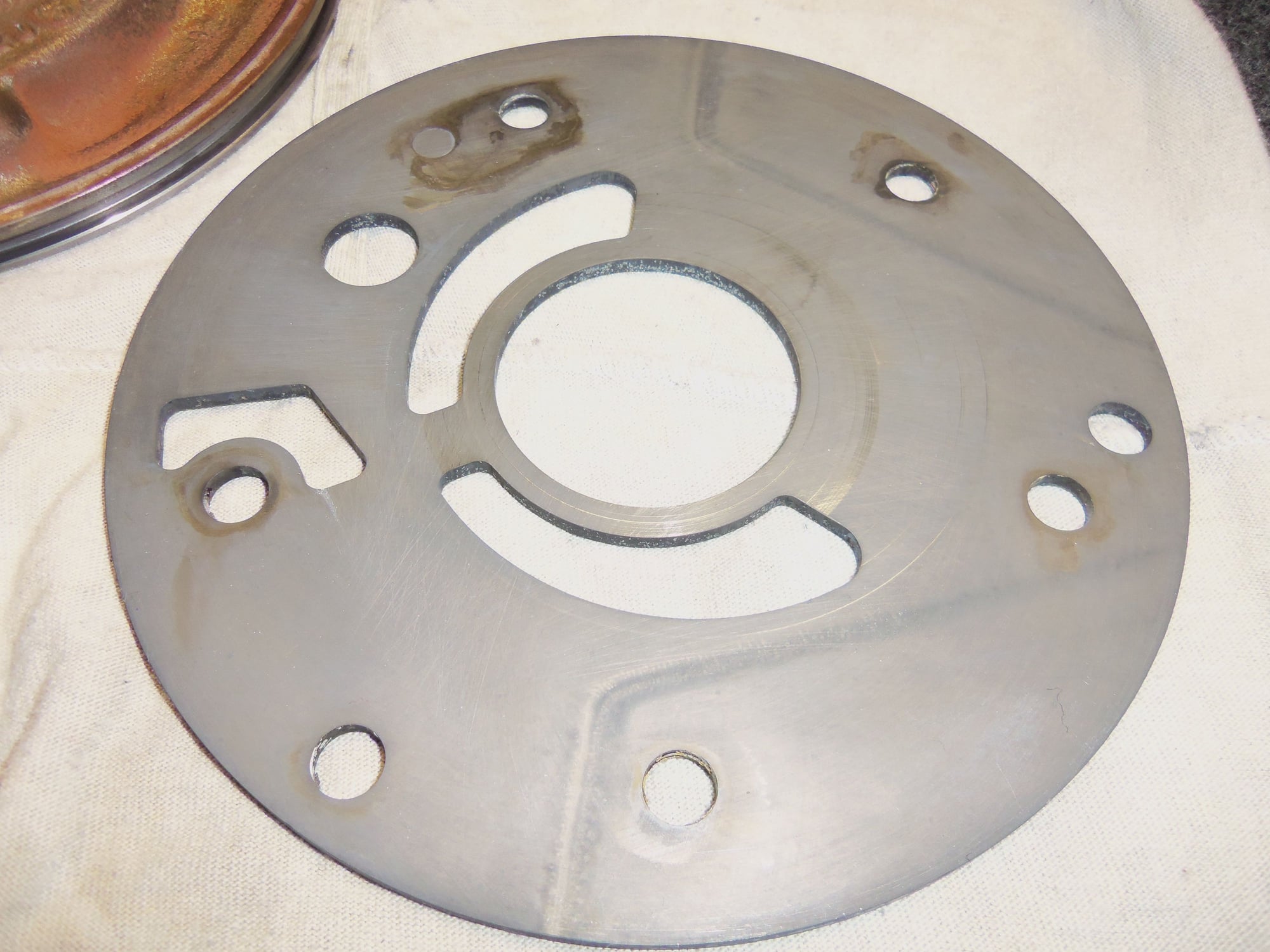
Separator plate has no burrs. The discoloration did not clean off with solvent and cannot be felt with a finger tip. I did NOT use scotchbrite on this plate. This side of the plate faces the pump gears.
Back side of the separator plate.
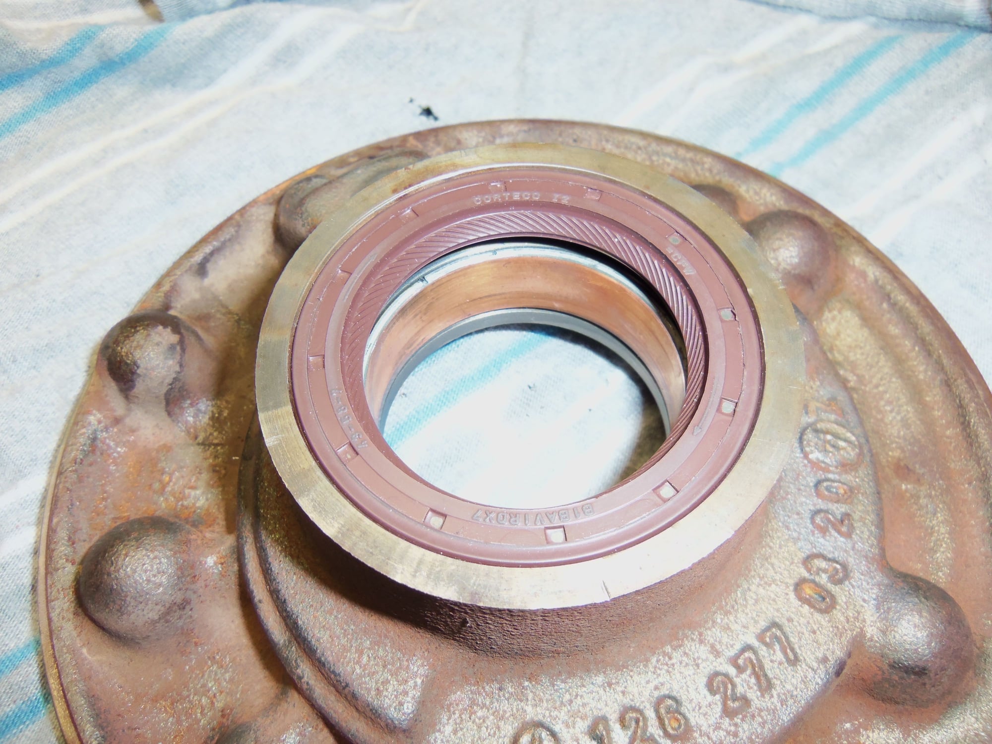
New O-ring and radial seal for the front pump.
New seal installed, but not yet lubricated.
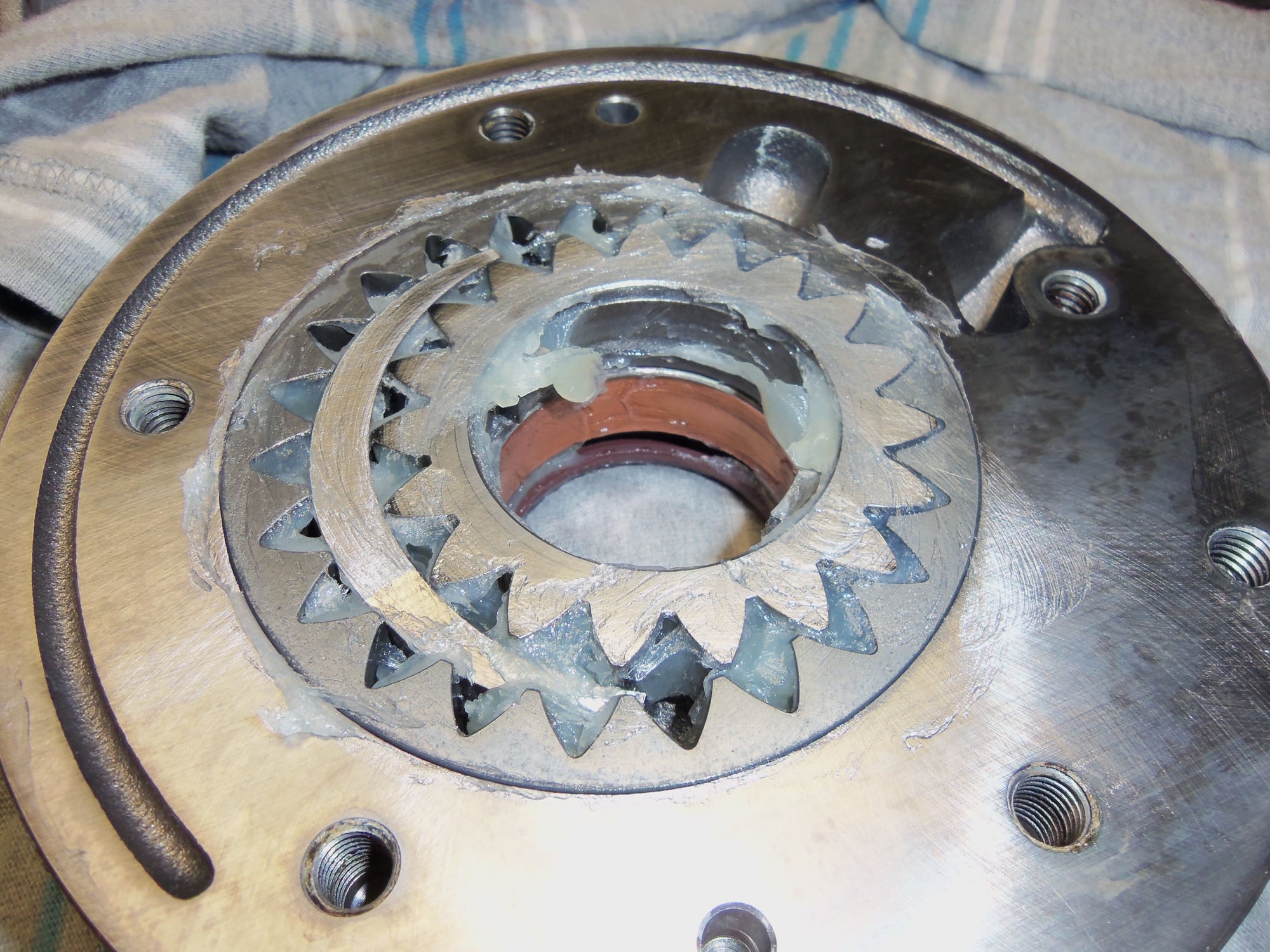
Pump gears reinstalled in front pump, in EXACTLY the same orientation as they came out. All have been lubricated with petroleum jelly. Note the petroleum jelly on the separator plate for the pump gears to ride on.
Close up of installed pump gears.
Front pump installed in pump cover assembly.
Note petroleum jelly in radial seal lips.
Back side of pump cover showing front pump mounting bolts.
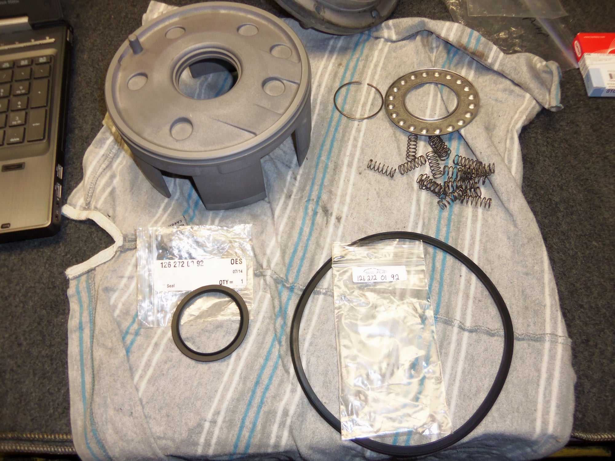
B3 piston installed onto back side of pump cover. I did this process VERY carefully. I did not want to fold over the lips on either the inner or outer seal. I used plenty of petroleum jelly as lubricant and pushed slowly, evenly, and gently. I think it went well. I did watch as the outer seal started into the pump cover to make sure the lip didn't fold over. Springs reinstalled in their wells.
Retainer and circlip installed.
New teflon seal rings for the OD of the B3 piston shaft, which seal into the ID of the K1 clutch drum.
Teflon rings installed, sealed/lubricated with petroleum jelly.
Close up of diagonally cut seal rings. I massaged the rings and used petroleum jelly to hold them into the grooves.
Another view of retainer plate and sealing rings.
Note groves on input shaft for sealing rings. (Earlier photo where B3 clutch discs and steels had not yet been installed.)
New sealing rings on right, old rings on left.
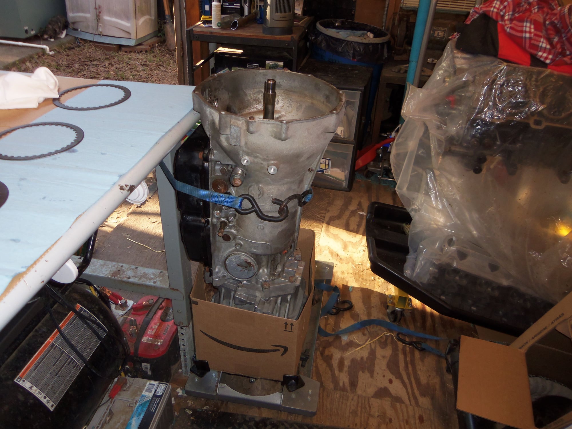
Transmission is turned up to sit on the differential cover on the transmission jack, then secured to the work bench with a cam-lock strap. Crude, but effective.
B3 clutch discs and seals installed, thrust washers installed around input shaft, all lubricated with ATF.
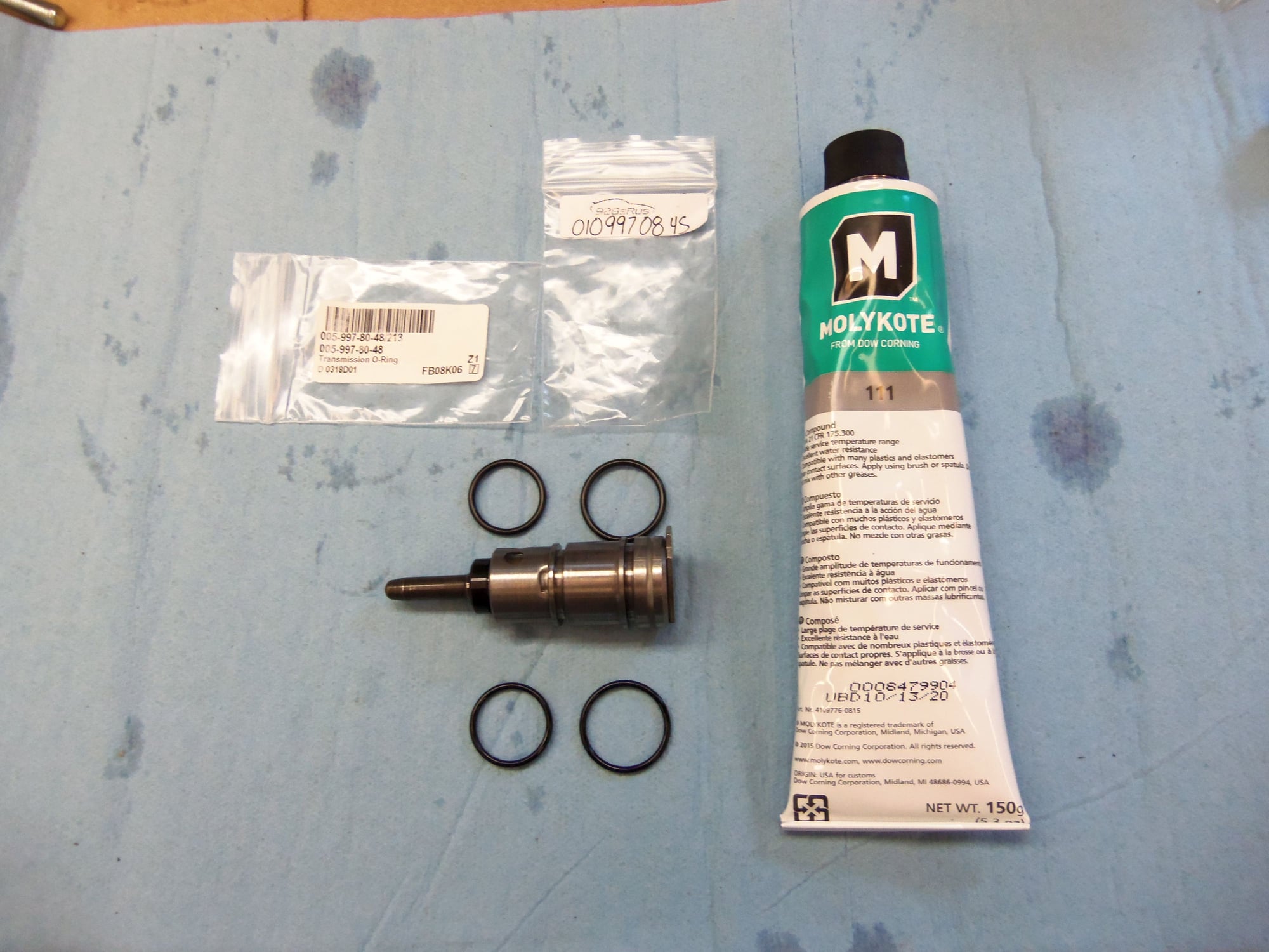
B1 brake band pressure pin with new O-rings at top, old O-rings at bottom. New O-rings were lubricated with Dow 111.
B1 brake band installed. As well, needle thrust bearing is installed around input shaft at its base.
Close up of B1 brake band and pressure pin.
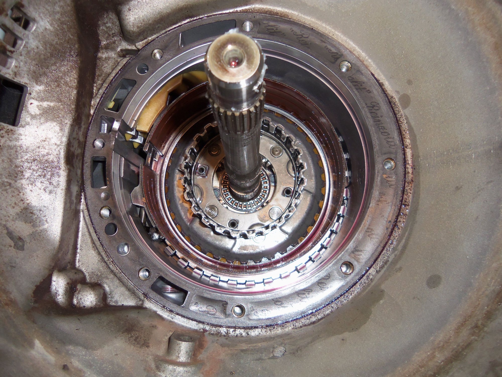
View of the sealing rings held onto the input shaft with petroleum jelly.
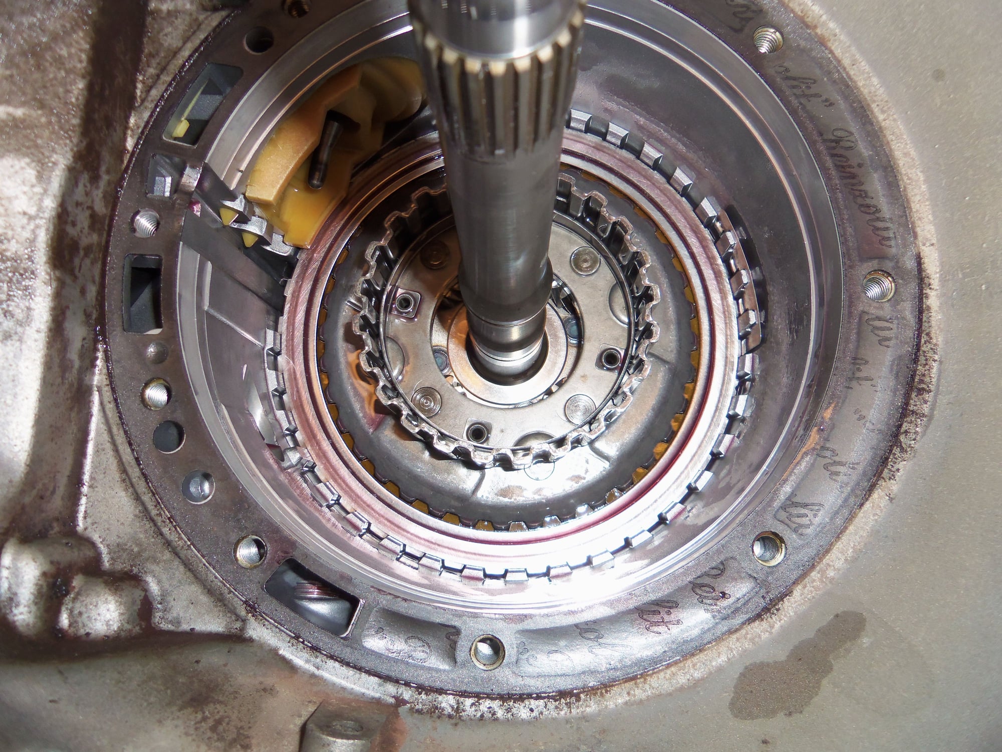
K1 drum, awaiting installation of its shims and needle bearing thrust washer. Note, I checked the clearance of the K1 clutch in the drum as per WSM Volume 3. Spec is 0.7mm - 1.2mm, this one was approximately 1.143mm (0.045"). Good enough for now.
Shims and needle thrust bearing installed into K1 drum, lubricated with ATF.
Installing this drum took a time or two, as I had to rotate it with my fingers, until everything lined up and all fell into place. More full disclosure: I resused the pump gasket. I have heard arguments from both sides, and I know the correct thing to do is replace the gasket. However, I did not feel confident I could get all the razor blade shavings out of the transmission casing when done. So, I left the gasket intact. Time will tell if I am a fool for doing this or not.
Alright, the previous few photos may be confusing and misleading. I had a helluva time with the K1 drum and the B1 brake band. As per WSM Volume 3, the K1 drum is to be installed first. It implies the drum just falls right into place. It does not. I had to turn the drum numerous times back and forth until everything lined up (the K1 clutch discs and the One-Way Clutch as well as the gear at the back of the K1 drum). Then the drum fell into place with a CLUNK. One of my experts let me know that if I had turned the pinion assembly(output shaft), that would have helped line up the K1 drum.
Next step is to install the B1 brake band. The WSM presumes you are following its disassembly/assembly sequence, and have the B1 accumulator out. I was not and it was not. So, when I tried to install the B1 brake band, I could not get the band anchor points to clear the various items at the bottom of the casing. I tried time and time again. Through sheer luck and prying, I got it all in place.
And then realized I had the B1 brake band installed backwards.
I had to use picks to catch the tiny lube drain holes on the outer surface of the K1 drum to pull the drum back up and out. I removed the brake band, turned it around, then reinstalled it. THEN I put the K1 drum back in.
Ugh...
Transmission front pump FINALLY reinstalled. I installed the pump squarely to the casing, with even gentle pressure so as not to disturb the sealing rings on the input shaft. I poured some ATF down the input shaft just because.
Torque converter reinstalled with a generous application of petroleum jelly to the input spigot. I turned the torque converter as I installed it and felt it clunk into place. I measured the distance from one of the drive lug pads to the face of the transmission casing, and got 16mm, just as specified in WSM Volume 3.
Completed torque converter cover and drive plate installed back on the transmission.
Drive plate bolted to torque converter.
Yes, I know the bolts in the drive plate are incorrect. This will be corrected in a later post.
Rubber plugs in the access holes for the drive plate bolts.
With that hurdle cleared, now onto other parts of the transmission...
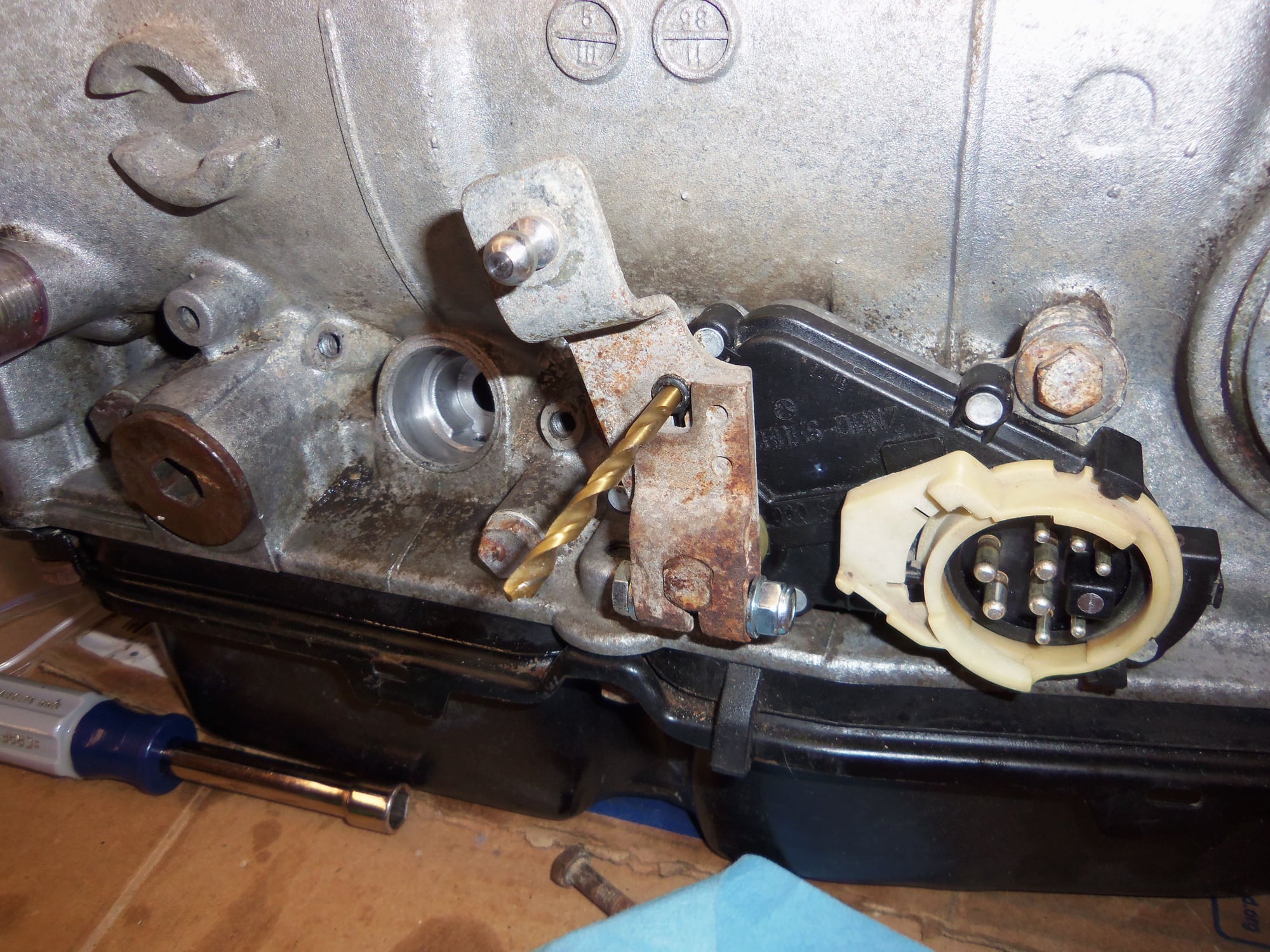
Aligned the shift selector switch and the manual selector lever with a drill bit, as per the WSM.
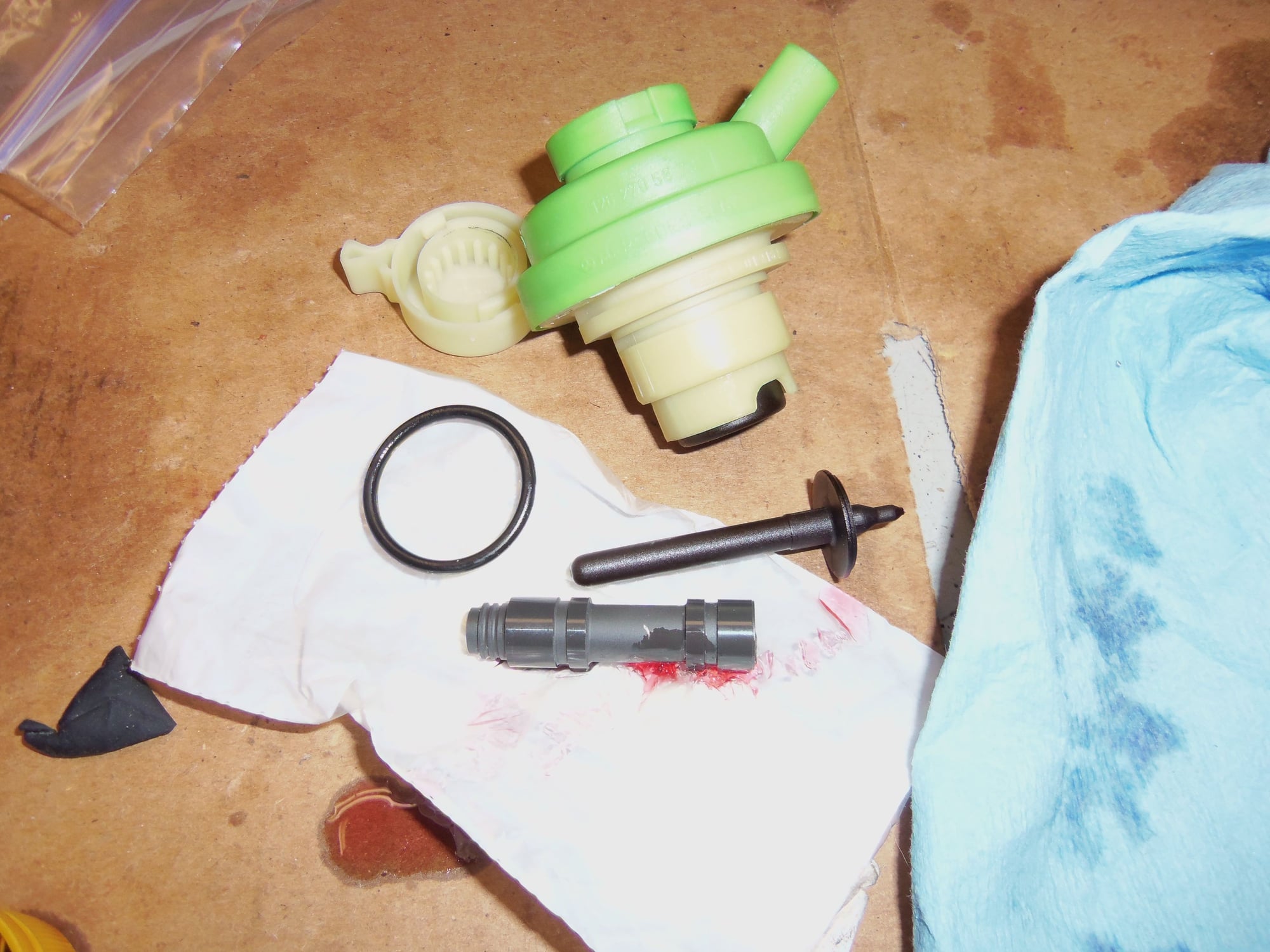
New style MB vacuum modulator, mounting O-ring, pressure pin, and modulator valve.
Vacuum modulator bore in the transmission.
Modulator valve and pressure pin installed in the transmission.
Modulator installed. I will properly set it after everything is running.
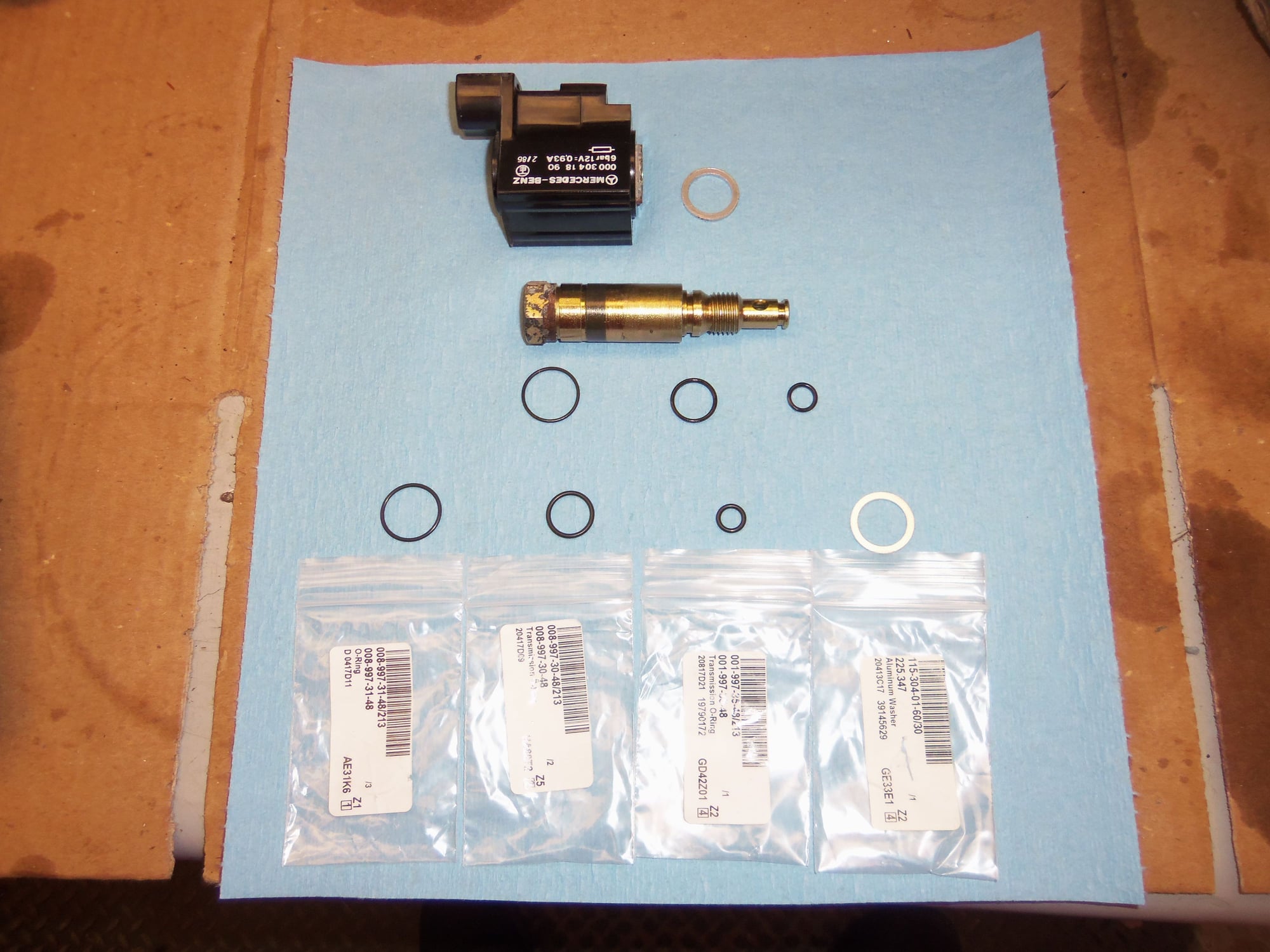
Cleaned kickdown solenoid coil, valve stem, and various O- and sealing rings.
O-rings are for the valve stem, new at bottom. Aluminum seal ring is for the solenoid coil to the transmission case.
Valve stem installed in the coil, all O- and sealing rings installed. I put a thin skim of PTFE sealant on the aluminum seal ring.
Kickdown solenoid installed back into the transmission.
Another view.
At this point, I rolled the transmission over to access the pan. Next on the agenda were the valve body and brake band servos.
Transmission flipped over for continued surgery.
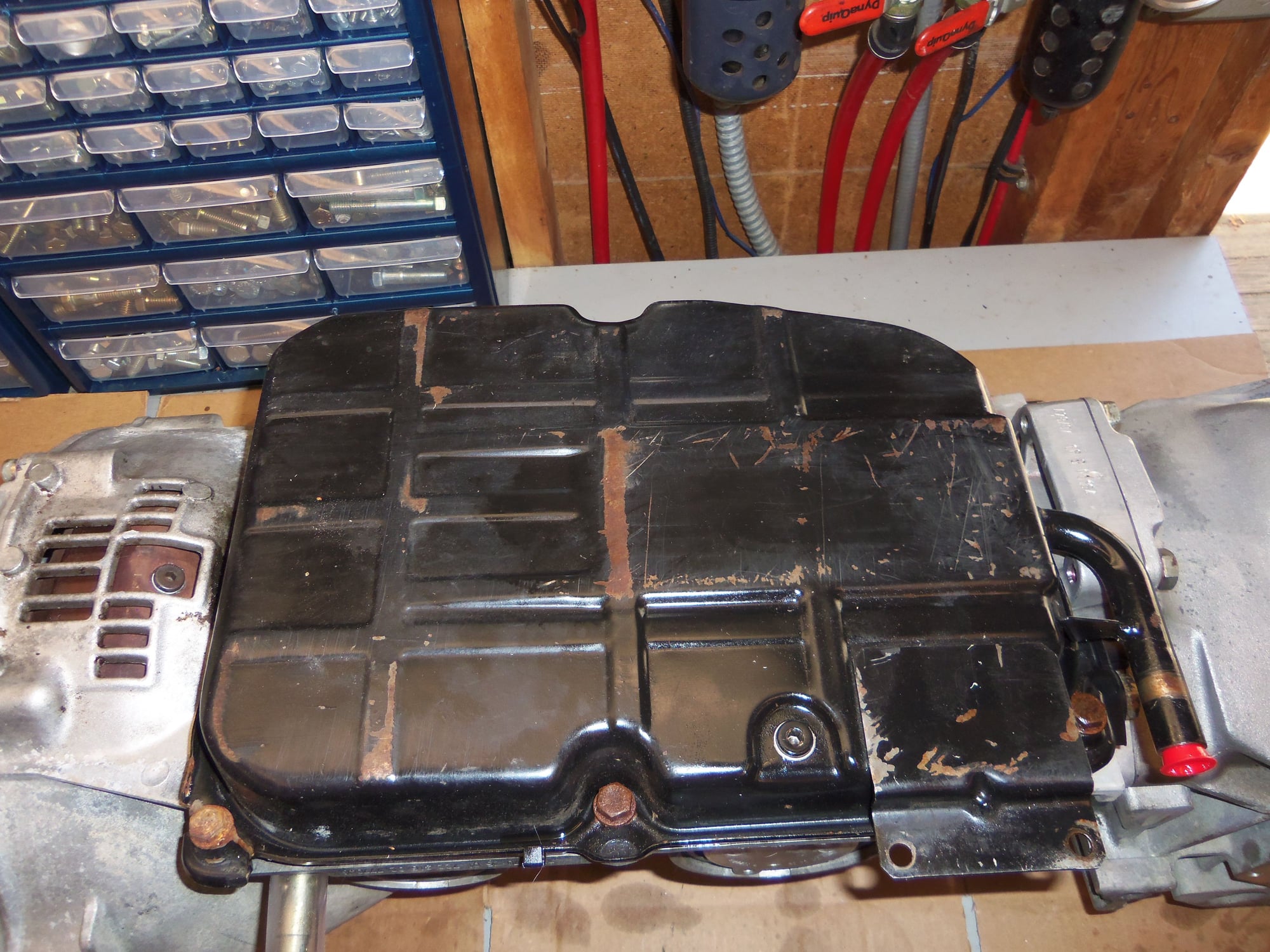
Pan comes off once again.
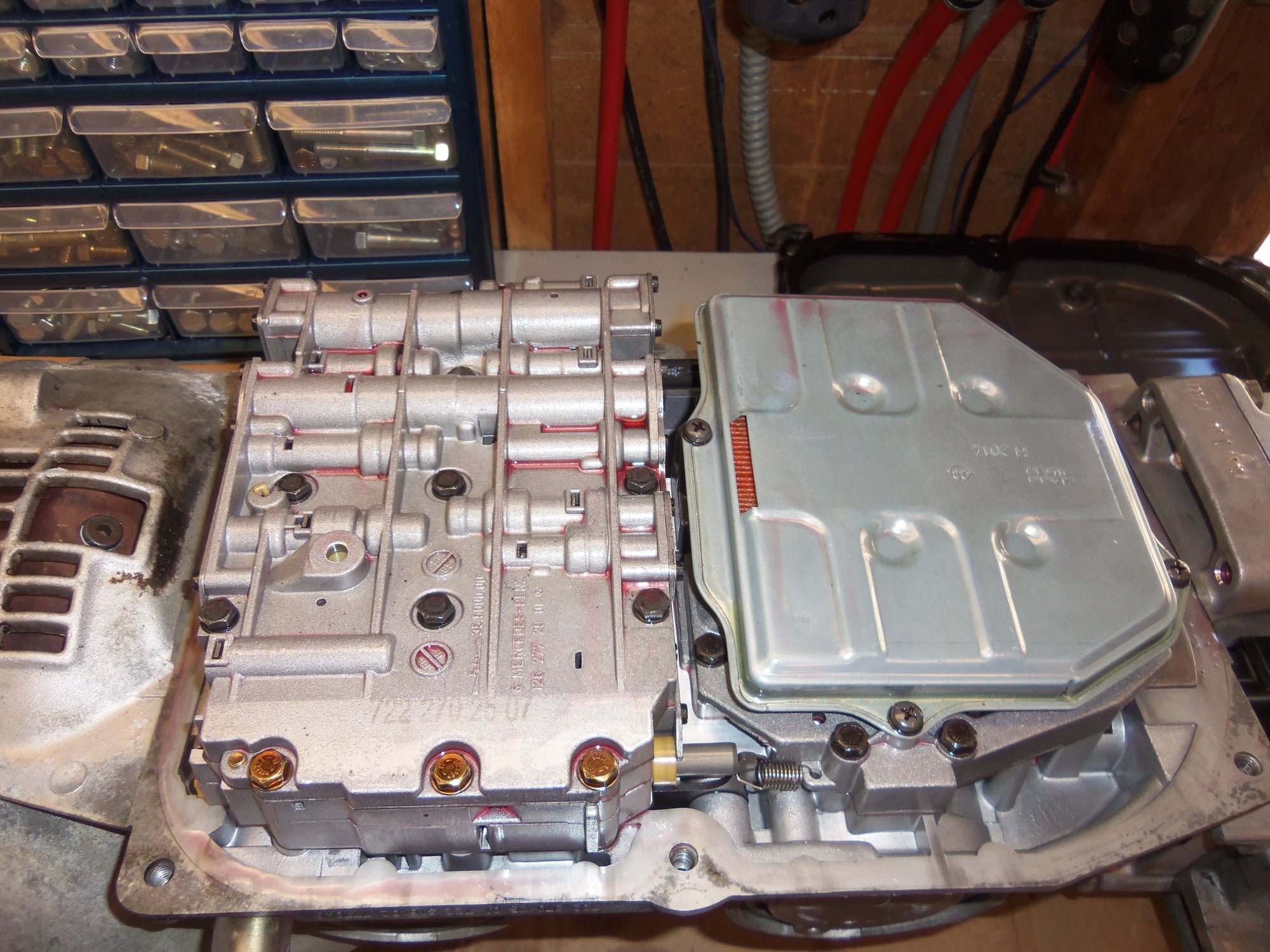
Valve body and fluid filter.
Lower cover is visible once the fluid filter is removed.
B2 servo cover.
B2 servo bore with cover and servo piston removed.
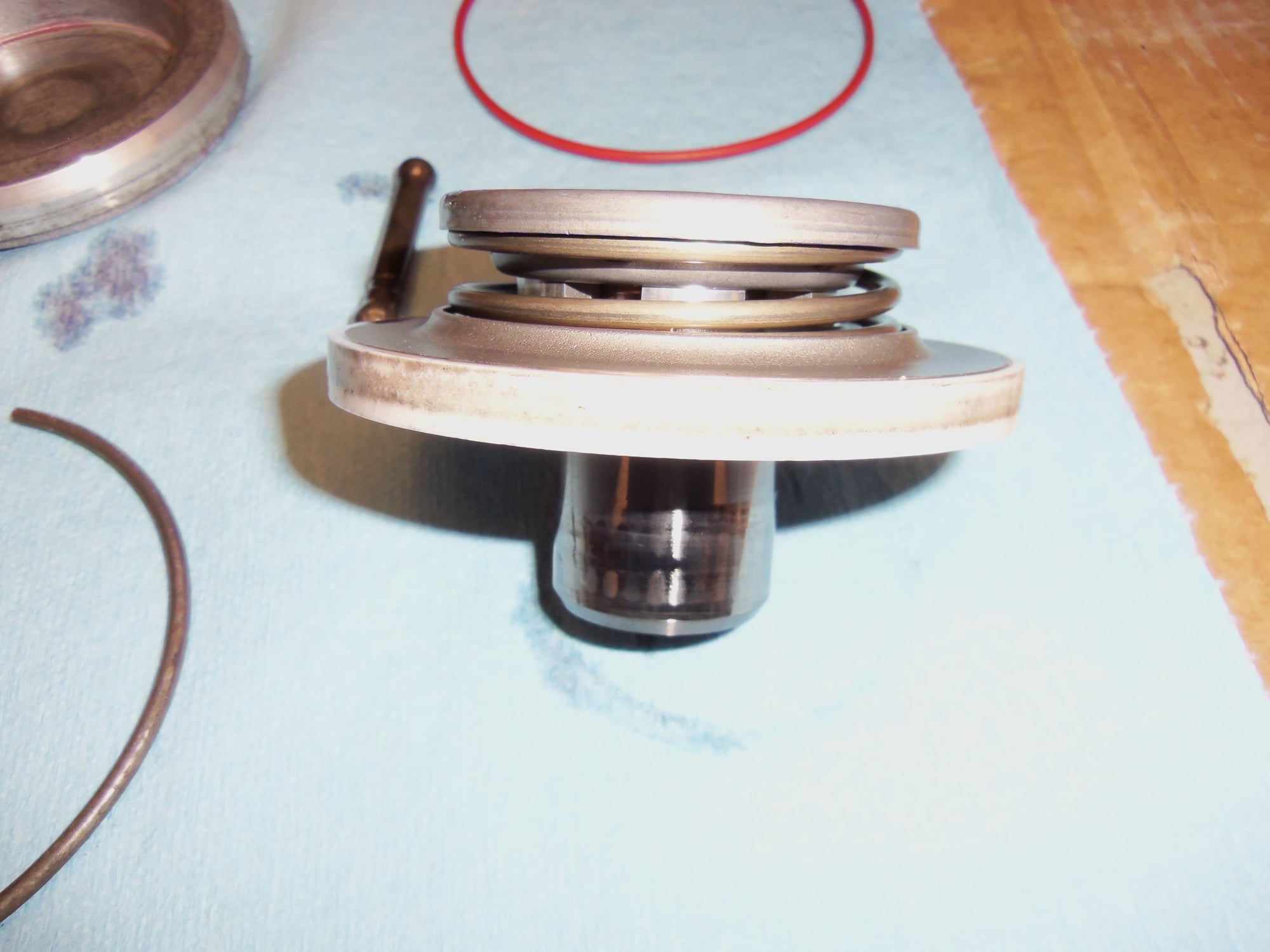
B2 servo cover, snap ring, sealing O-ring, piston assembly, and pin. All of these parts are original.
Outside of piston assembly.
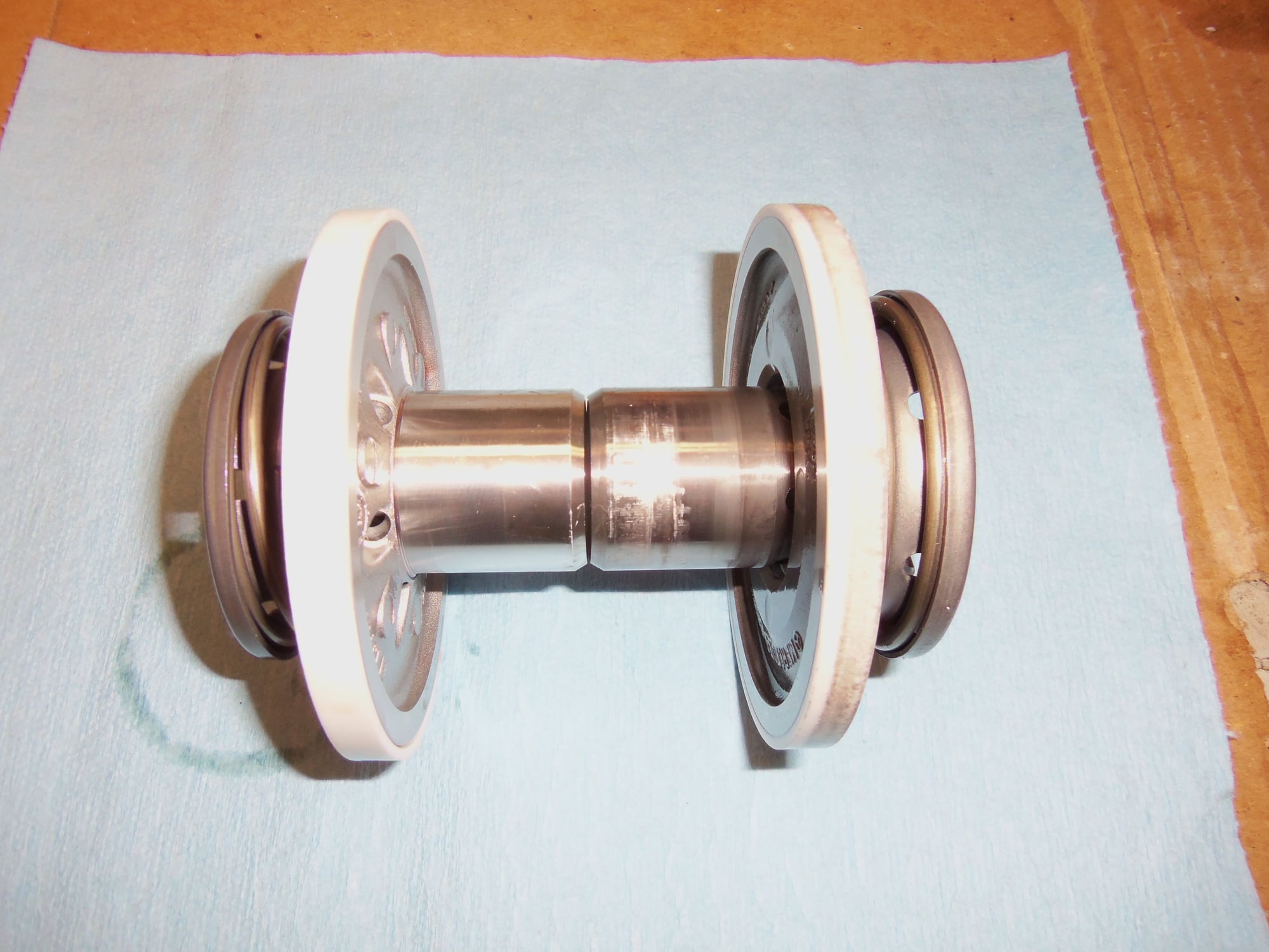
Side view of piston assembly.
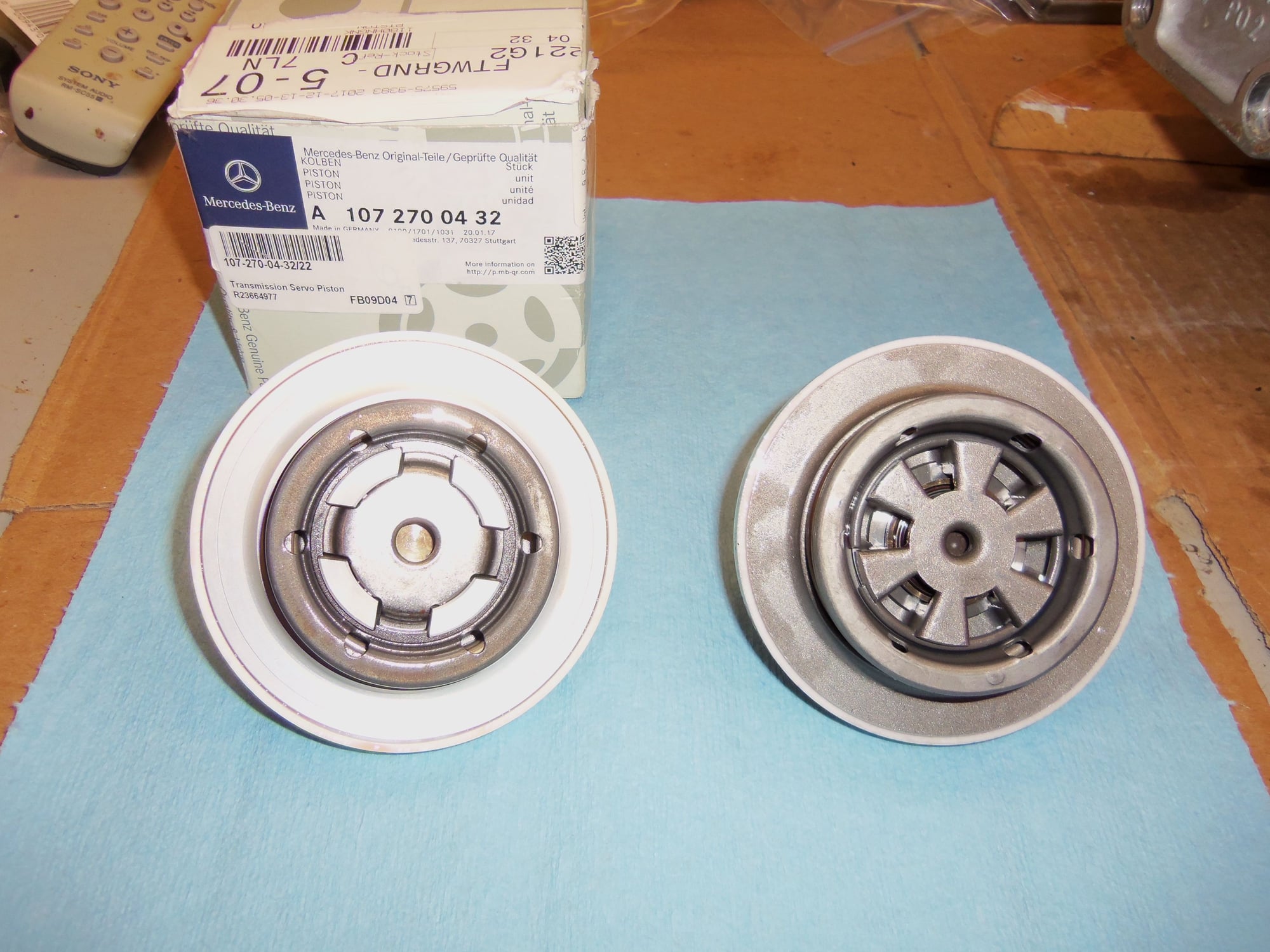
New updated MB B2 piston assembly. I am replacing the B2 piston because of known failures with the original parts. The piston breaks, and you no longer have any forward gears. Updated piston is less failure prone. I am not installing the new piston at this moment. There is more disassembly to be done.
Comparing insides of new and old pistons. New on left.
New piston on left. Note wear on teflon seal and snout of old piston.
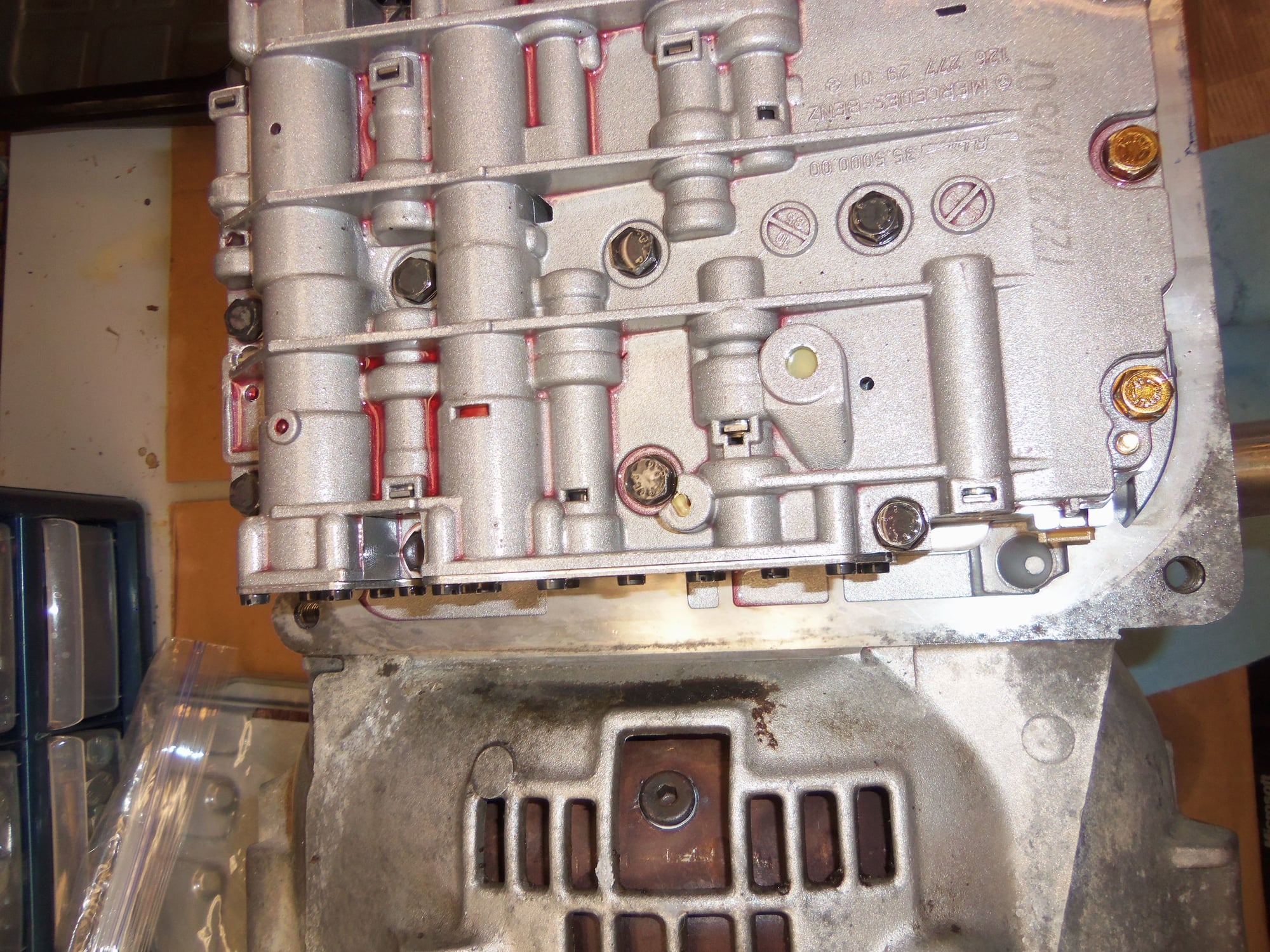
View of valve body bolts.
Same.
Same. Also good for reference on which way the valve body fits. Did not take photos of valve body removal because I documented this back in July of 2016 in my fiasco of trying to replace the vacuum modulator.
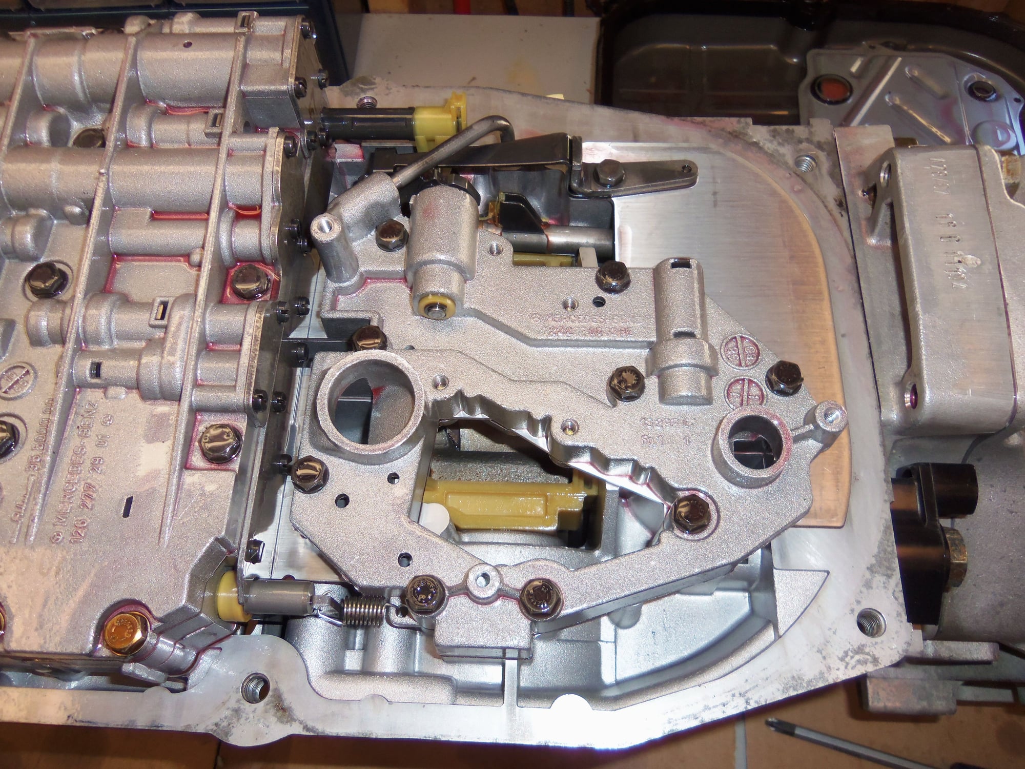
Lower cover mounting.
Note oil injector tube and manual shift lever detent spring.
Another view.
Detent spring and backer removed.
TV cable lever return spring.
Lower cover mounting screws, detent spring, and TV cable lever return spring.
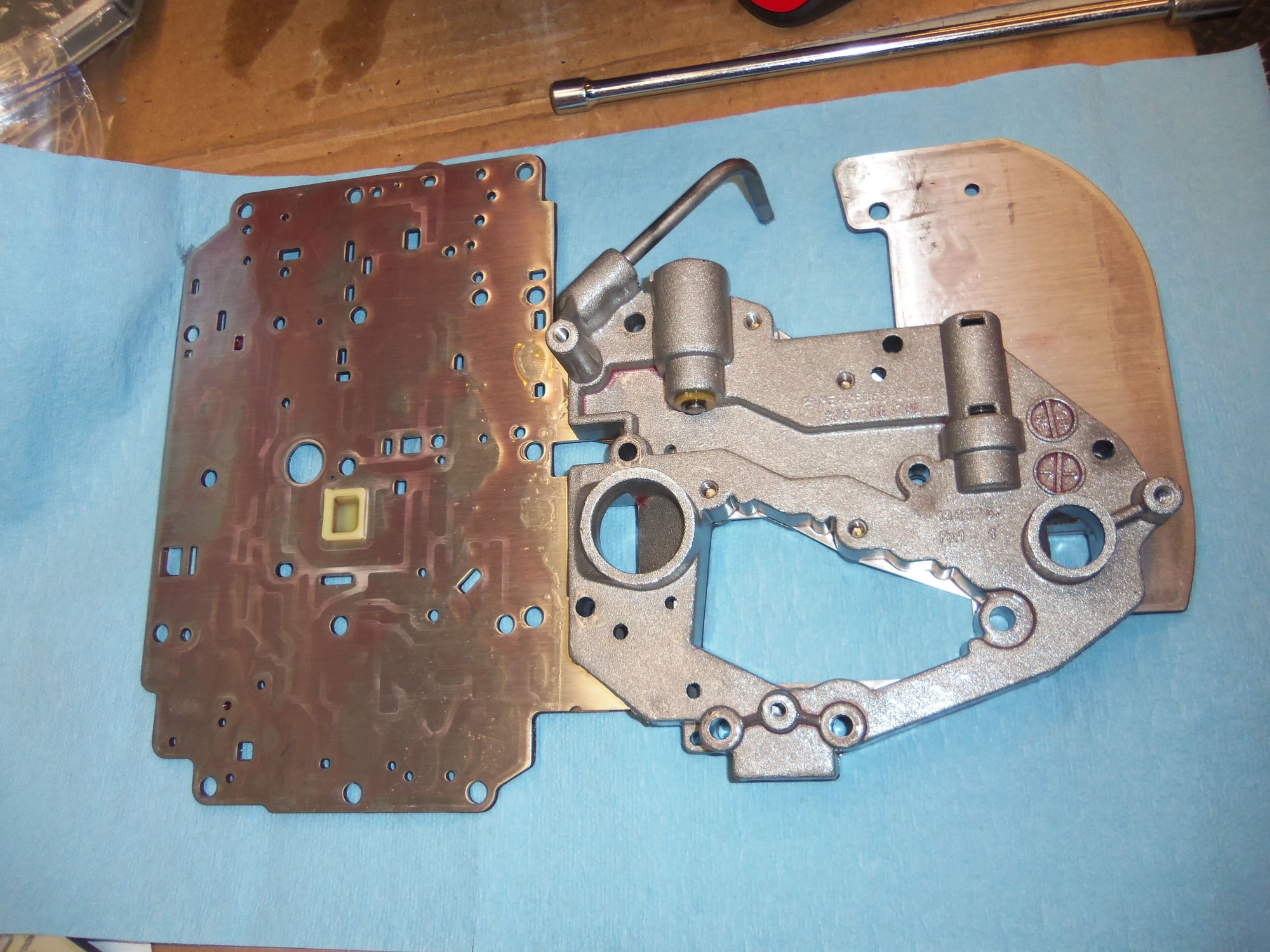
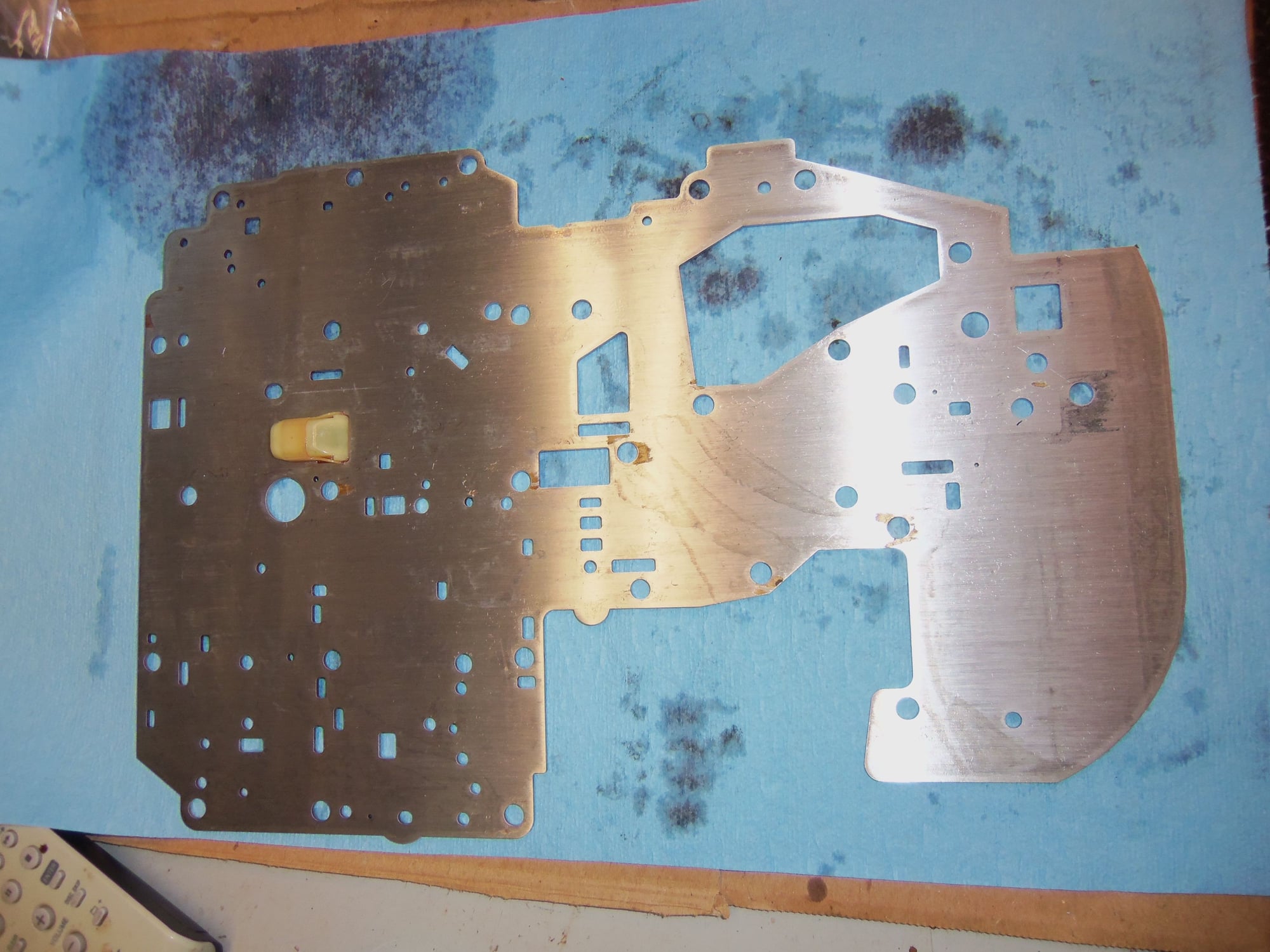
Lower cover and separator plate removed.
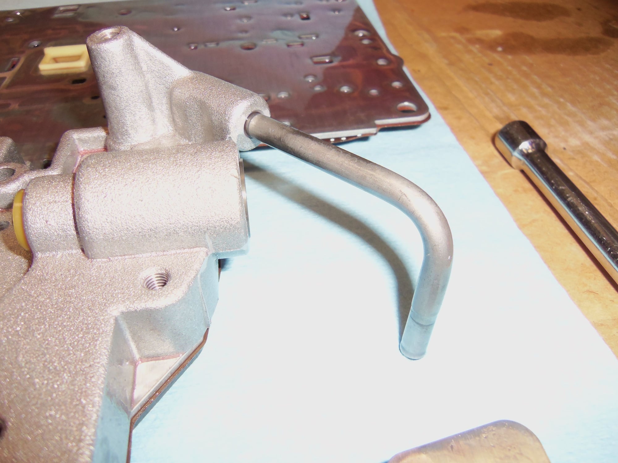
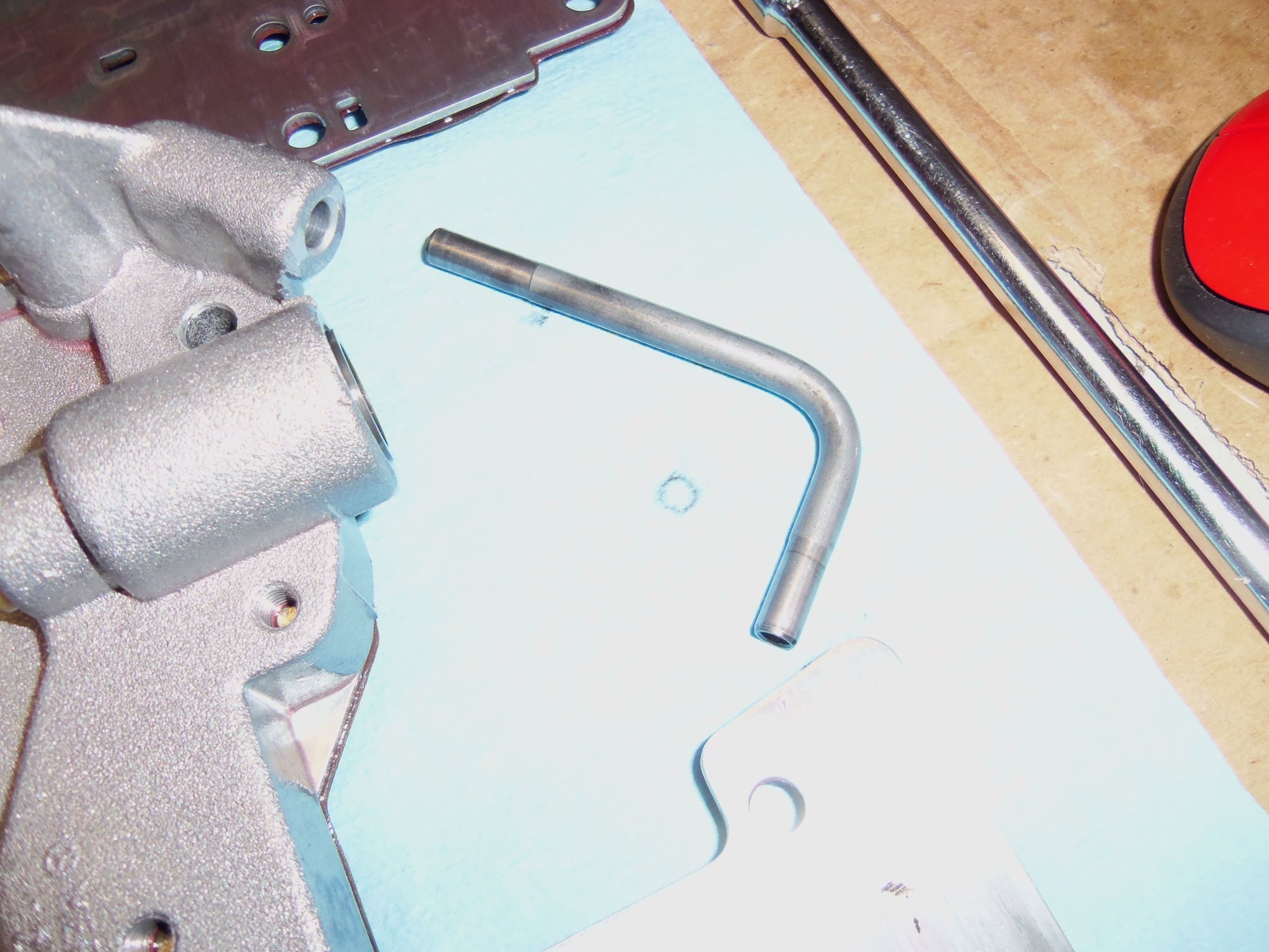
Oil injector tube.
Tube removed. Note the long side goes into the lower cover, short side goes into the transmission.
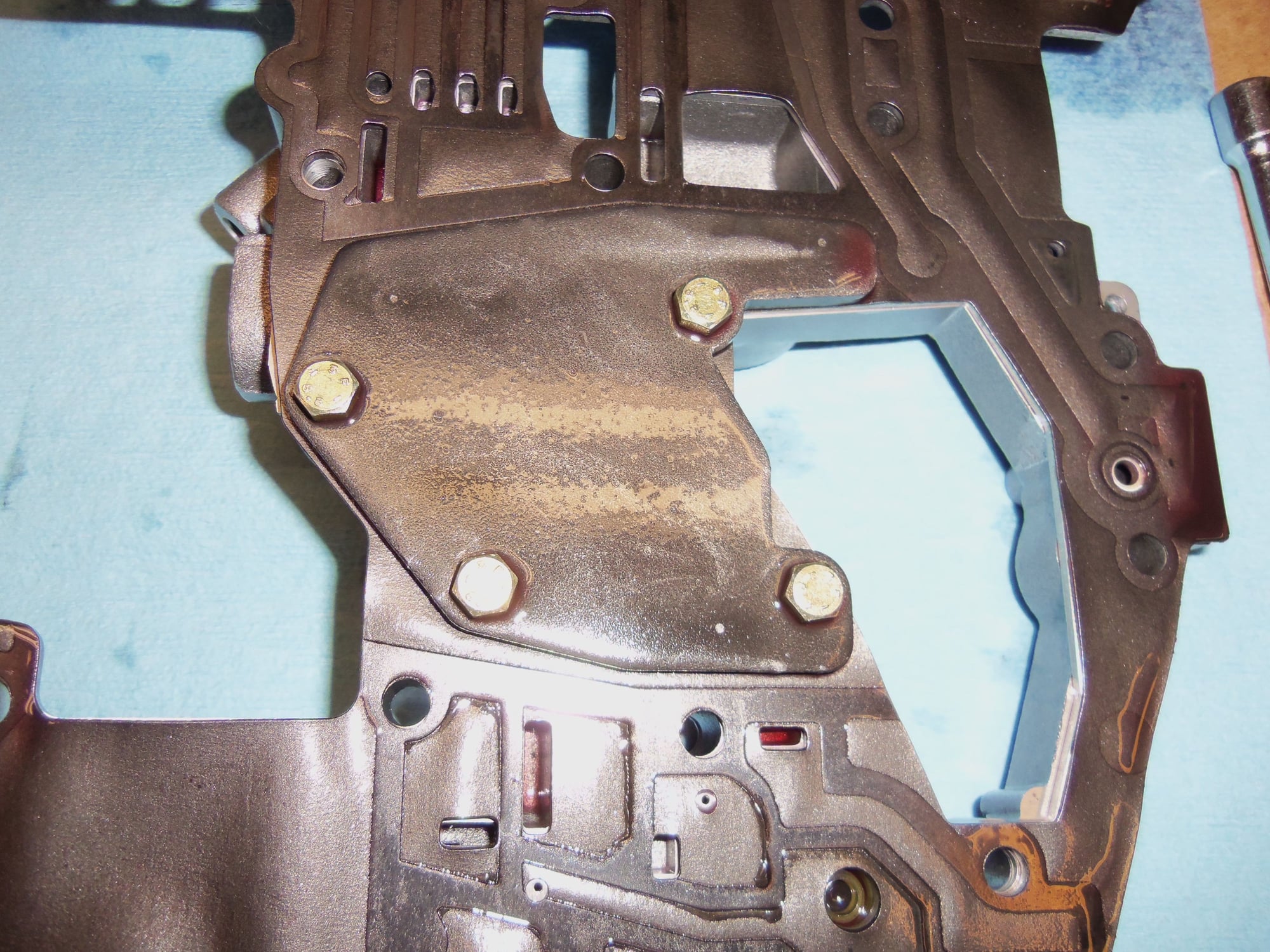
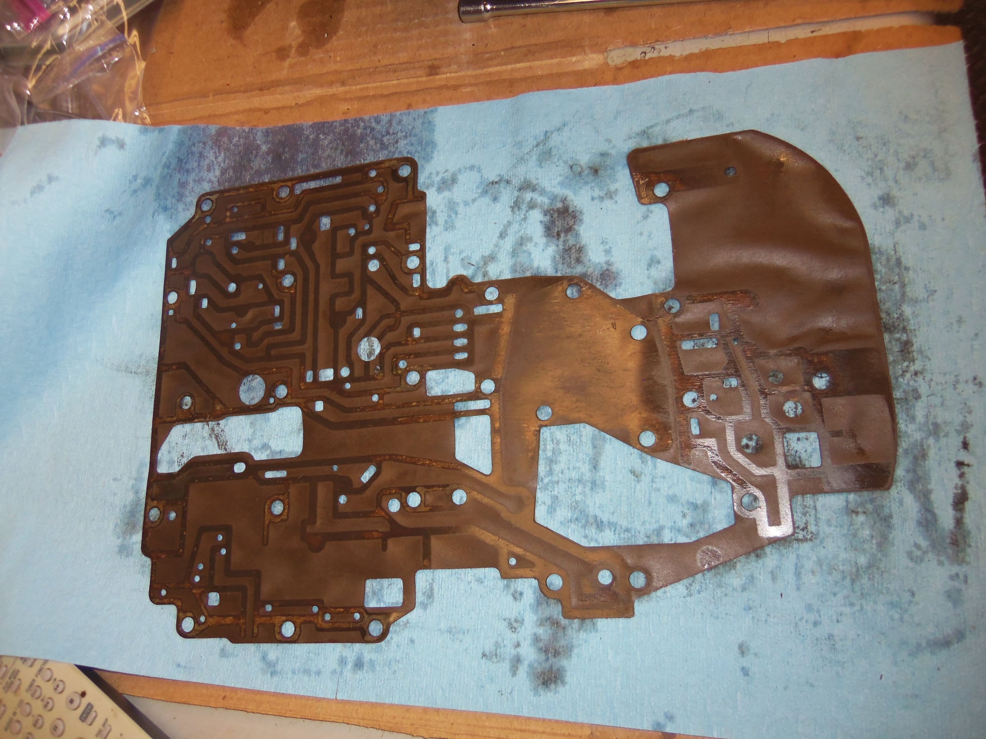
Separator plate and lower cover flipped over. Note the lower cover is still bolted to the separator plate. See the odd shaped plate and 4 yellow cad bolt heads in the approximate middle of the gasket.
Closer view of reinforcing plate for lower cover on back side of separator plate.
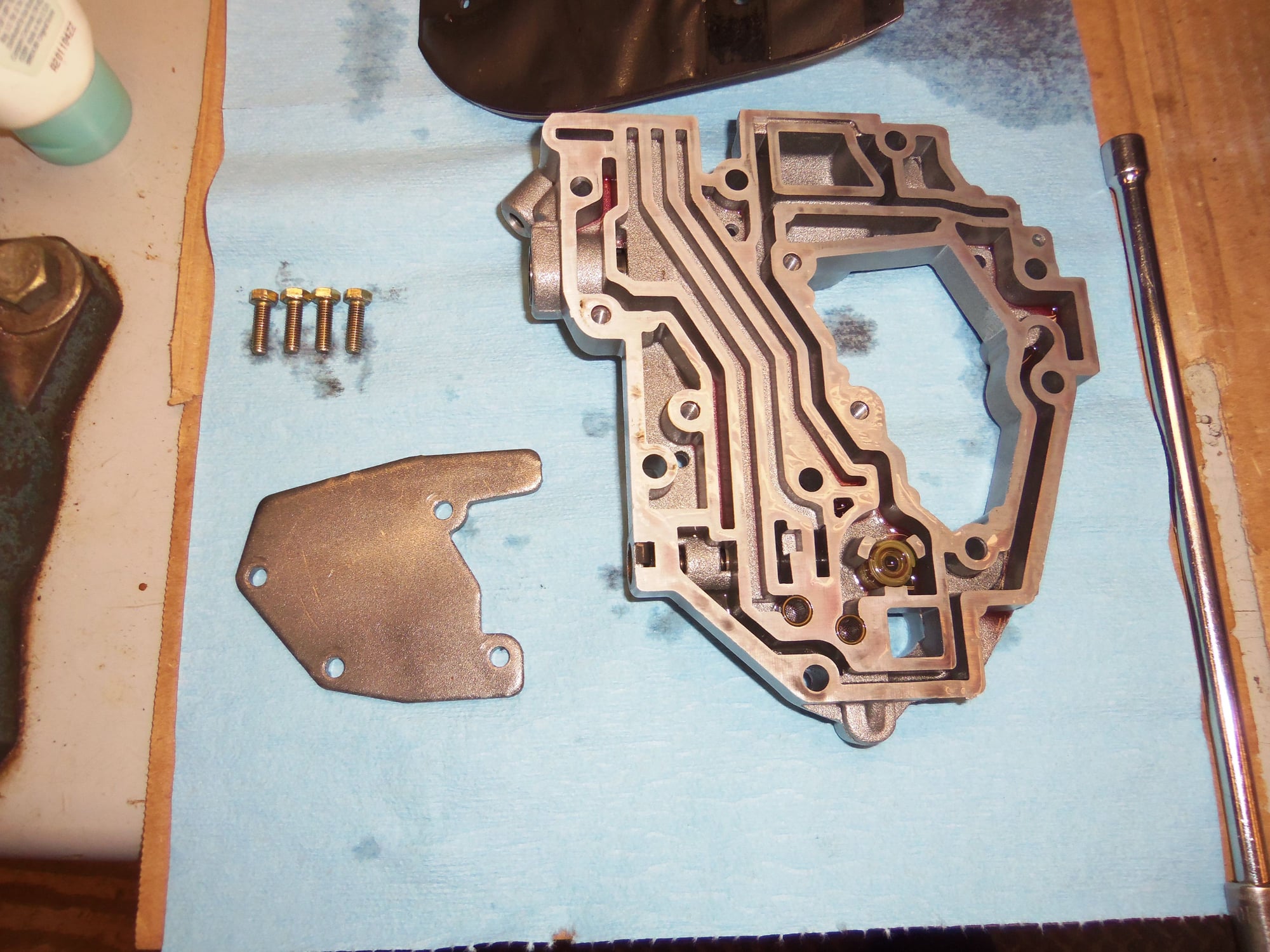
Lower cover and reinforcing plate unbolted from separator plate.
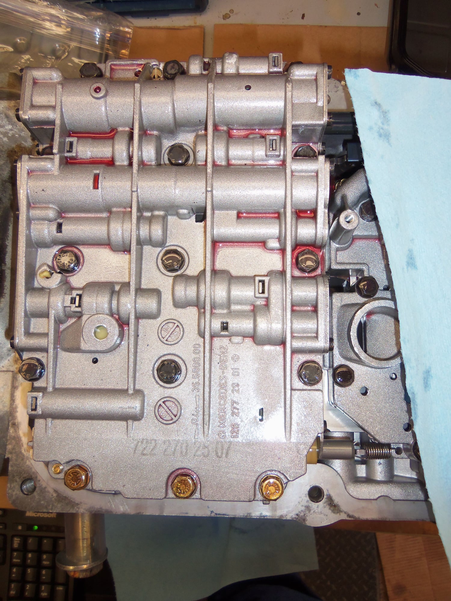
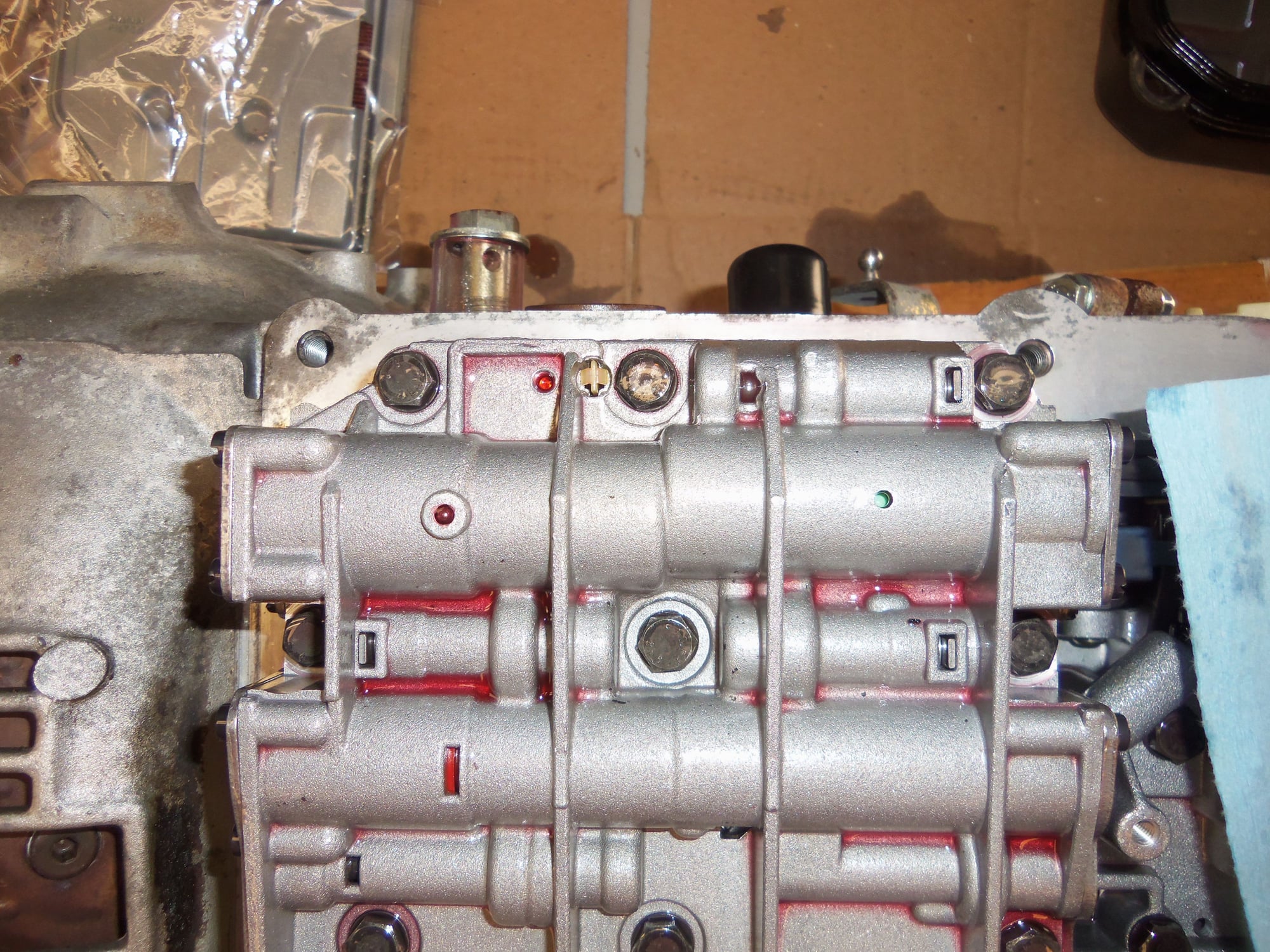
Separator plate.
Separator plate gasket.
Objective for removal of the valve body and lower cover: access to the transmission to measure B2 brake band clearance.
Seth the open heart surgeon! Wow!! You are "da man" . Awesome documentation as always. Are you doing a straight rebuild or are you adding any upgraded "performance enhancing" components?
Thank you, Chris!
I am not a surgeon, that would be Rob Edwards. I am just a specialized hack who is too stupid to know his limits.
This is not a rebuild, just seal replacement, B3 clutch discs replacement, and checking brake bands. However, I AM installing a shift kit in the valve body. Because.

 02-02-2019, 11:35 AM


 )
)