When you click on links to various merchants on this site and make a purchase, this can result in this site earning a commission. Affiliate programs and affiliations include, but are not limited to, the eBay Partner Network.
Am in the similar process, had my trans rebuilt by a Mercedes mechanic, have the Black Sea bearings, was debating the GB shaft, will probably go with it, I don't want to have to pull this apart ever again.
Not quite a dead thread revival, but I am trying to get things back up to speed. Being an adult and having life get in the way is such joy.
Anyway, as I left off, my intent was to learn how to remove the transmission without removing the rear suspension. (I know, idiot.)
I did it, but am still an idiot.
For any newbies (or oldbies) who have never done this, FOLLOW THE ACCEPTED METHODS AND REMOVE THE REAR SUSPENSION, THEN REMOVE THE TRANSMISSION AND TORQUE TUBE AS ONE UNIT. IT WILL BE SOOOOOOOOOOO MUCH EASIER ON YOU!!!
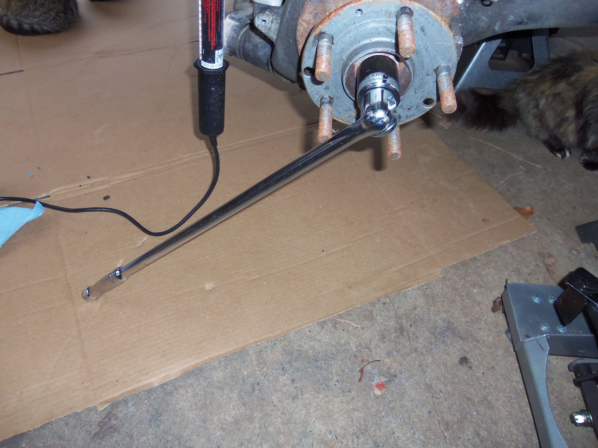
For prep work, I removed the socket head bolts securing the CV axles and revmoved them from the drive flanges. To be able to apply torque to the mounting bolts, I put a socket and long breaker bar on the big nuts on the splined shafts at the hubs. The breaker bar bucked up against the floor of the carport. With the axle ends free, I put the mounting bolts back in and secured them with nuts. This would keep the end plates from falling off. I hung the free ends of the CV axles from the rear suspension cradle with big zip ties.
Strong, good fitting hex bit socket for bolt removal.
Breaker bar and socket keep hub/CV axle from turning while breaking inner joint mounting bolts loose.
Glad to see no dirt, crud, or corrosion in the drive flanges.
CV axle end mounting bolts back in with nuts.
Mounting bolts and nuts keep the end plates from falling off.
Free end of axle secured with zip ties to suspension cradle.
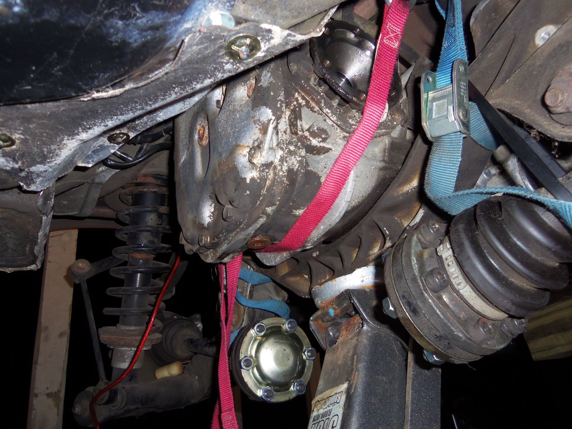
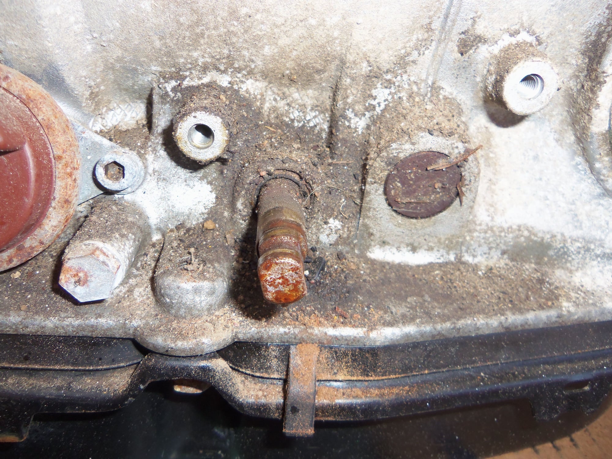
I ran a cam-lock strap around the underside of the differential casing, hanging it from the rear anti-sway bar. Then I removed the lower mounting bolts for the rear transmission mounts.
The intent was to lower the front of the transmission and lever/wiggle/the differential casing over the rear suspension cradle.
The best laid plans of mice and men...
Red cam-lock strap around differential casing. Ignore blue straps for now.
Straps hung from rear anti-sway bar, as per WSM.
Front of transmission supported for the moment.
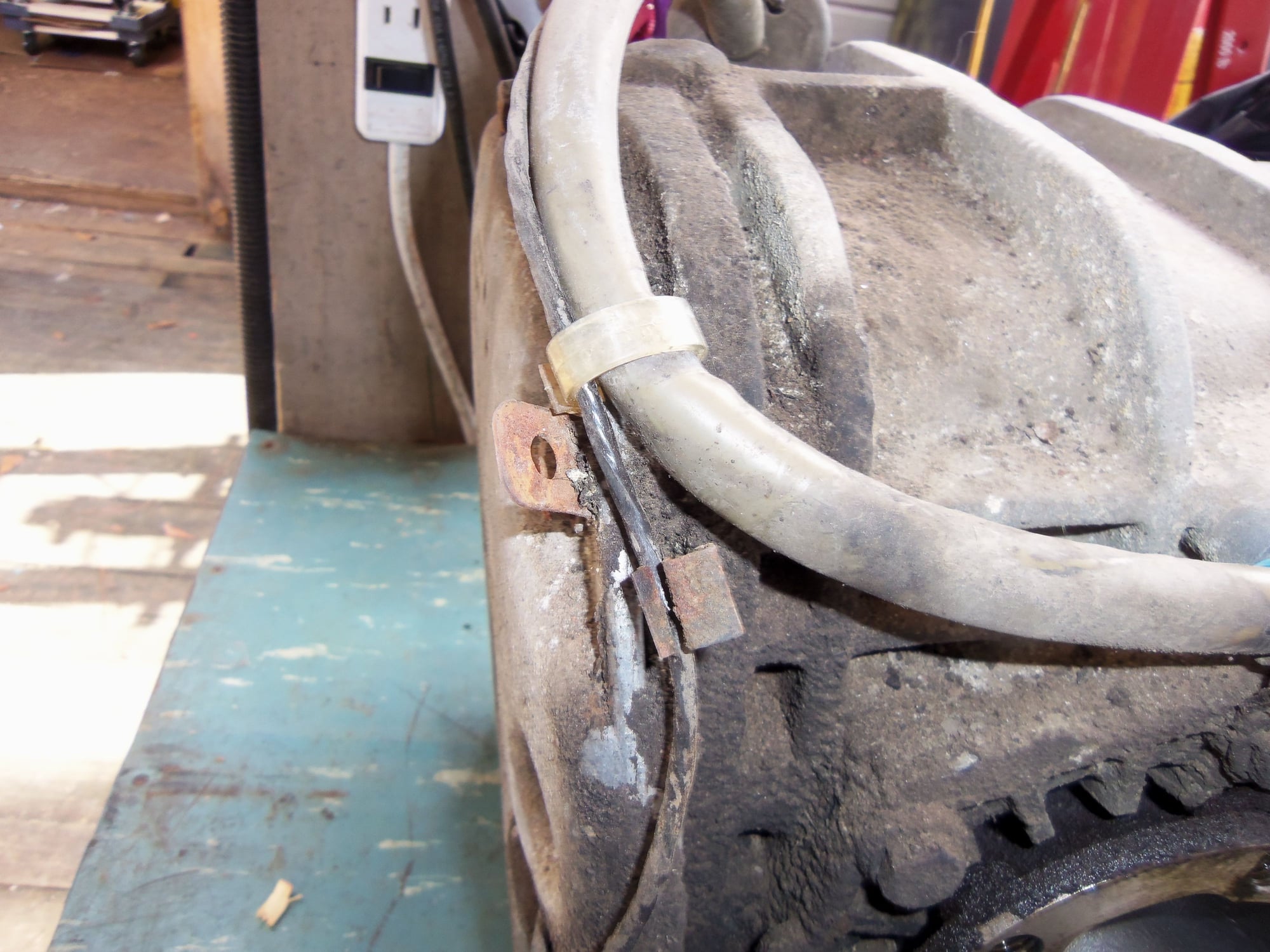
First I had to disconnect the wiring for the transmission in the rear hatch area.
Wiring for ABS and transmission at the front of the rear hatch area, just above the battery compartment.
Whatever markings were on this harness label are long gone.
Transmission wiring harness must go through this hole to be removed with the transmission.
These plugs are for the range selector switch and kickdown solenoid.
This plug is for the speed pickup on the differential rear cover.
Plug assembly unscrewed from the body.
Little plug was surprisingly difficult to get apart.
I WAS able to get the differential casing up and over the rear suspension crossmember and the free the transmission. It took a bit of doing, though.
I bought a pretty sweet little transmission jack from Harbor Freight. This turned out to be the key. This jack raises MUCH higher than I expected, and the head moves in two axes. By wiggling, jiggling, lifting, lowering, tilting, cursing, etc...I was able to get stuff to move. However, I ended up having to lower the rear suspension cradle a little bit to get that last little bit of clearance I needed.
I disconnected the rear shocks from the body, and disconnected the rear anti-sway bar links from the lower control arms.
Using two more cam-lock straps, I supported the rear suspension cradle from the rear anti-sway bar. By unbolting the cradle mounting bolt, but not completely unthreading them, I was able to lower it just enough. (Yeah, I know I am an idiot and am well into fool's errand territory with this one.)
Rear upper shock mount and cover.
Cover removed. DO NOT REMOVE THE NUT ON THE CENTER SHAFT!!!
Put these away so nothing got lost.
Disconnected rear anti-sway bar links.
Blue cam lock straps to support the rear suspension cradle.
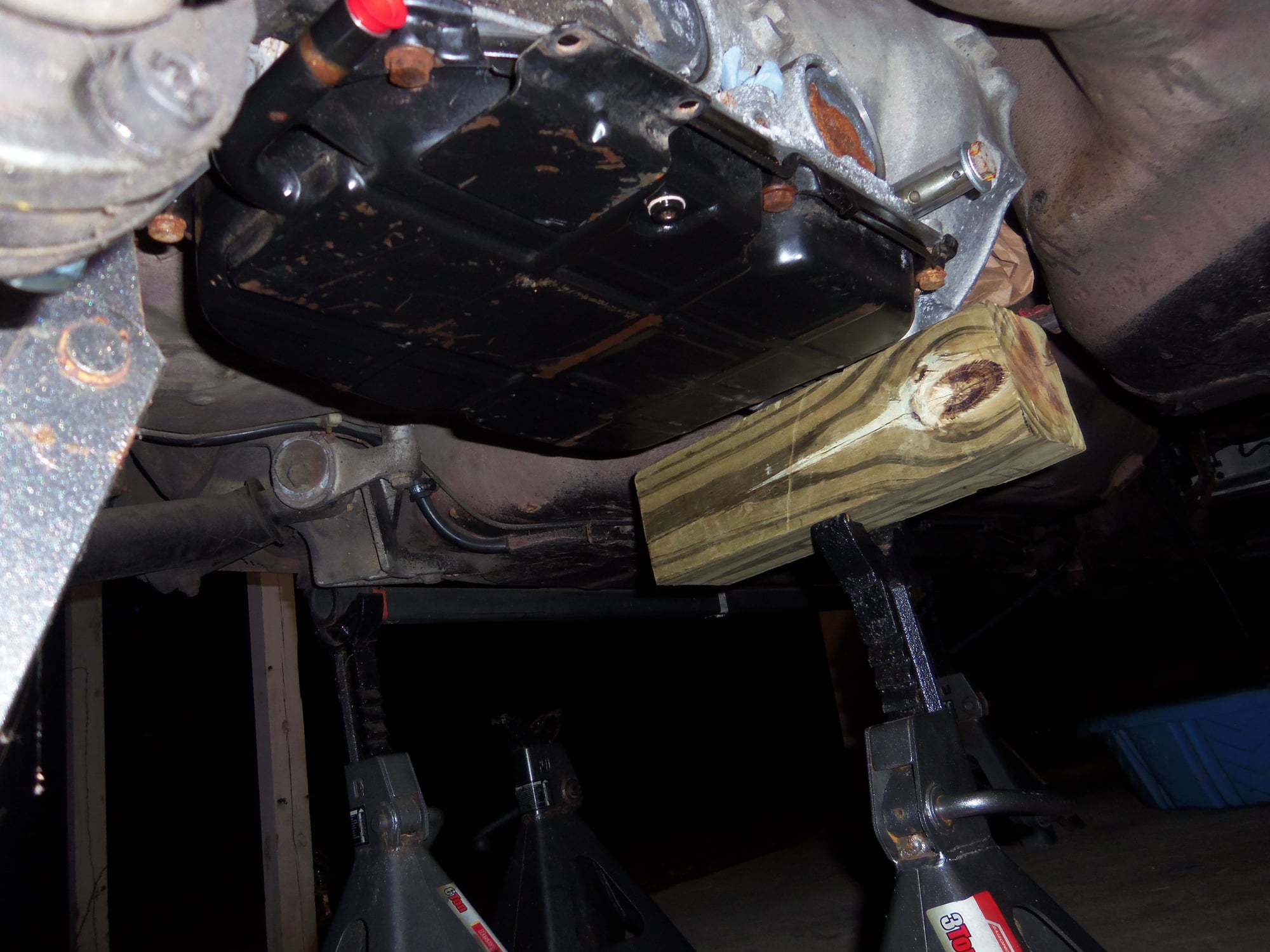
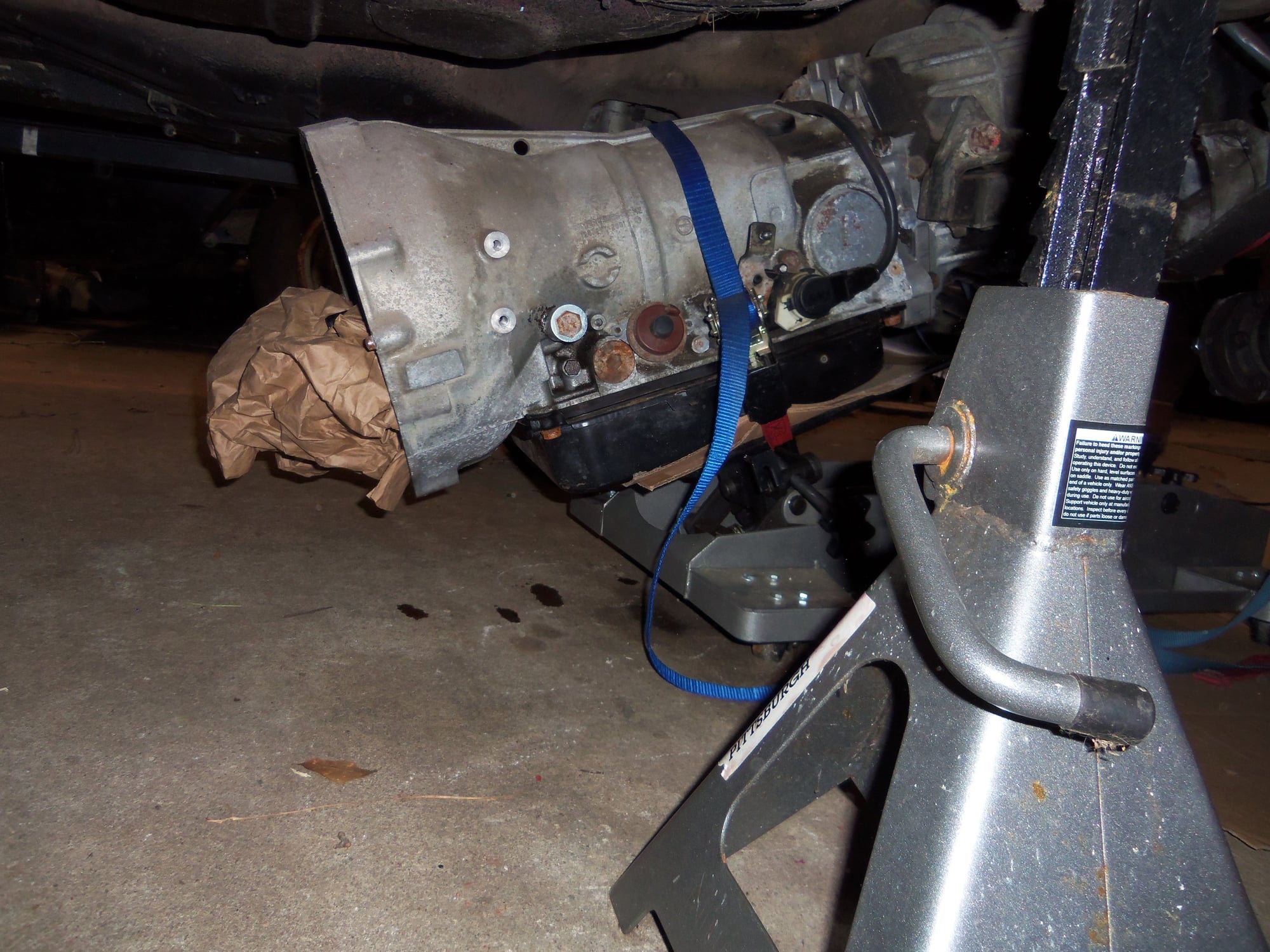
Transmission on the HF transmission jack. I had cardboard under the transmission fluid pan, and ran a couple of straps around the transmission to the head of the jack. It was reasonably stable.
Differential casing free of the lowered rear suspension cradle! Note the transmission harness and rubber plug pulled out of the body hole.
Steep angle on the transmission needed to get the differential casing to clear.
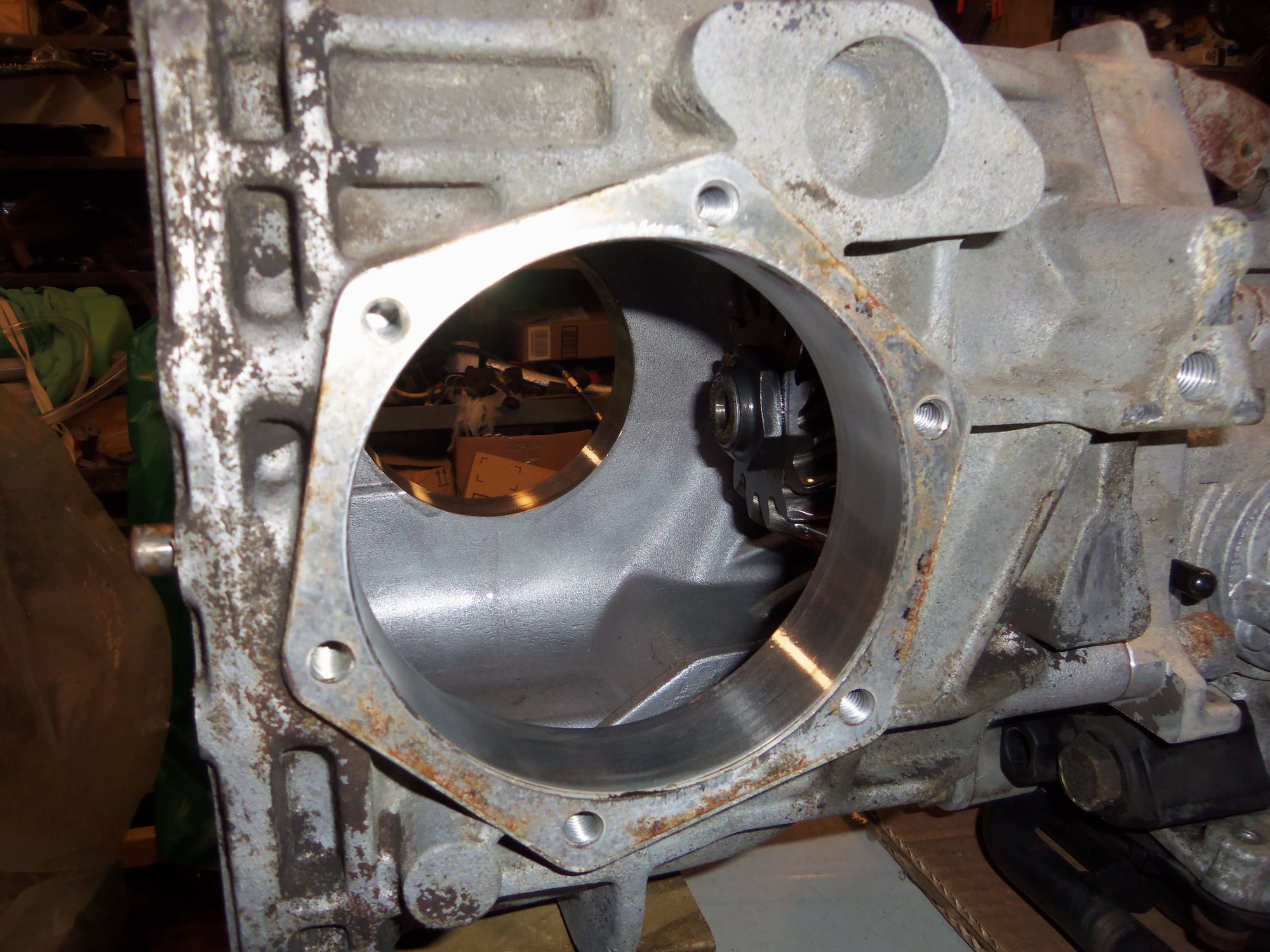
Body area where the differential casing used to be.
HAHA!!! I got the transmission out without 'removing' the rear suspension! My intent was not not disturb the rear suspension alignment. Feeling smug, I went to roll the transmission out from under the car.
And it didn't fit...
I had successfully removed the transmission without removing the rear suspension. Too bad it would not roll under the rear suspension cradle to get out to the wheel well.
With proof I didn't know what I was doing staring me in the face, I did what I should have done in the first place. I dropped the rear suspension.
That was pretty anticlimactic, since the rear cradle bolts were already loose and the shocks were disconnected at the body. I used one of my floor jacks to slowly lower the rear suspension assembly down onto a small rolling wooden platform. It was a tad unsteady, but all I had at the moment. I rolled both the rear suspension, and then the transmission out from under the car from the passenger's side rear wheel well.
Rear suspension dropped onto a little wooden platform. Transmission on the jack. Finally out. Rear suspension stabilized on the cart with big zip ties. Nothing but class here.
Let me back up. I missed a portent of the future. Reading up on removing the rear suspension, I saw that most people just removed the eccentric bolts from the lower control arm front mounts. They left the mounts bolted to the body. That was my intent as well. So, I made match marks on the eccentrics so I could get them back near where they were. I was resigned to getting a full four wheel alignment done at this point.
So...With my impact, I tried to remove the nuts. Nothing. I got out the breaker bar, and commenced to break the threads off one of the eccentric bolts. The shank was nothing but rust. Plan B: unbolt the front control arm mounts from the body.
Match marks on mount and eccentric. Note corrosion...
This went badly. Sheared the threaded end off the eccentric with the seized nut.
Yeah...not getting any better.
At least everything was now out and I could get a good look at it all.
Empty wheel well.
Underside of rear.
Right side.
Left side.
Looking straight up at the rear anti-sway bar.
I was able to raise the transmission jack high enough that it was a short lift to get the transmission onto my outside work bench. There, I took stock of what I had.
168.*** mile A28/07 transmission assembly.
As I looked closer, I noted good and bad:
Good: no MAJOR corrosion or dirt, though there was some healthy surface corrosion on things, wiring harness looked intact, and had all its clips
Bad: transmission mounts shot, vacuum modulator vacuum nipple broken off(knew that), harness clips were very brittle, rubber covering on range selector switch plug where the cable comes out was cracking and coming off
'Clear' clip.
Speed pickup.
'Pink' clip.
Note cracking of rubber on plug where cable exits at the right.
With the transmission on the outside bench, I could start disassembling the little bits in preparation for cleaning. I removed the transmission mounts, the wiring harness, the manual gear selector lever, the range selector switch, the speed pick up, and the fluid reservoir vent hose. I left the vacuum modulator in place to seal its bore.
Well used transmission mounts.
Still show factory applied Optimoly.
Manual gear selector lever and range switch. I think it is in 'P' now.
I think the selector lever is in '2" now.
Manual gear selector lever removed to show the actuating arm on the range selector switch.
Range selector switch removed, showing the manual gear selector shaft.
Range selector switch male pins are nice and clean.
Range selector switch plug gasket is intact.
Range selector switch plug female pins are nice and clean.
Definite need for cleaning at the kickdown solenoid.
Kickdown solenoid plug is dirty, but intact.
I did not realize the speed pickup just sits in a well on the differential cover.
Fluid reservoir vent hose is in OK condition.
Barb for fluid reservoir vent hose.
With all that done, I remounted the transmission on the HF transmission jack. Out in the driveway, I raised the jack as high as it would go. I taped a trash bag over the torque converter end of the transmission and liberally sprayed the entire thing down with foaming engine cleaner. Then...pressure washed the h*ll outta it. I made a mess of myself, as I usually do when pressure washing, but it was worth it. Transmission was much cleaner to go up on the work bench in the shop. I was able to roll the transmission into the shop on the jack, then again raise it all the way up for a short lift onto the work bench.
Transmission jack provides a good way to pressure wash all around and under the transmission.
Transmission is now on the work bench in the shop.
You're never an imbecile for trying it a different way. It's what we do and we'll never find the real shortcuts until we try them. There are recommended ways and there are the right ways. They aren't always the same?
You've given me a lot of good advice Seth. I'm pretty sure not all of it came from the book.
Last edited by Otto Mechanic; 01-31-2019 at 01:24 AM.
Otto: I am an imbecile for not doing it right the first time. I should have pulled the engine, and then the transmission/torque tube from the get-go. This would have saved alot of effort.
There is a common, underlying theme to my posts on the Red Witch over the past almost 3 years (). I didn�t WANT to take her apart. I resisted common lore in the 928 world. Yet, everything I said I WOULDN�T do, I DID. Just in the wrong order.
it is what it is. I have written, and will continue to write my threads to be informative and helpful. If nothing else, a newbie can read my threads and get a sense of how not to do certain things certain ways.
I am glad that you have learned something, though!
Chris: Buckle your seat belt. I am just getting started. I am documenting months of incremental work. This will take us deep into the A28/07 automatic transmission and differential, with rear suspension goodies as well.
Spolier: there are Eibach�s and Koni�s involved.
Post pressure washing inspection of the transmission on the work bench inside my shop.
Some surface corrosion on the B1 brake band servo cover.
A little corrosion on the governor secondary pump. Not going to remove that. Kickdown solenoid looks much cleaner.
Upper bolts for separator plate between transmission and differential.
Separator plate between transmission and differential casing.
Differential cover still needs some cleaning. Note cast in 'AUTOMAT' on differential cover, and lack of drain plug at the base of the cover. 86.5 928's had an exhaust pipe crossover in this area. The drain plug is on the bottom of the differential casing.
Left side of the transmission.
Most of the crud has been blasted away.
Slight corrosion on the governor cover. No reason to remove that.
Little plastic transmission vent cover is still intact.
Right side drive flange and bearing cap. Note casting for future PSD actuating cylinder...
Left side drive flange and bearing cap.
Little plastic differential vent cover is still intact.
One of my goals for removing the transmission was repairing the leak between the differential casing and the tail section of the transmission. Gear oil had been seeping out of the weep hole on the separator plate. This meant the radial lip seal at the pinion shaft was seeping gear oil. My initial intent was to replace both the radial seals on the pinion shaft. With the advice of experts, this quickly changed to replacing all the seals in the differential and most of the external seals on the transmission.
First phase was disassembly and removal of the differential:
Differential cover unbolted and gently removed from its dowel pins. Note the little black sheet metal bracket at the bottom. This is actually the top of the cover. The bracket is part of the differential breather system. It acts as a baffle to prevent raw gear oil from entering into the breather chimney cast into the top of the differential casing.
Open differential casing. Note horizontal slot at top. This is the opening for the breather vent chimney, which leads to the little black plastic breather on top.
Aluminum magnet wheel for the speed pickup on the cover. Note little round magnets evenly embedded in aluminum wheel.
Ring gear and markings.
More ring gear markings.
Non-LSD differential. Oh well, it is what it is. Ring gear wear pattern doesn't look terrible. However, I am NO expert.
Removing bolt for left side drive flange. Punch through bolt hole bucks up against casting rib in bearing cover.
Splined drive end of drive flange, also showing machined sealing surface for radial seal.
Look inside at female drive splines in differential side gear.
Inner race of differential side bearing, as well as radial seal.
'D' stamping I added on the left bearing cap, as well as a match mark to the differential casing. This way I won't mix up the bearing caps, and will install them in the same index position.
'D' stamping on the left drive flange so I won't mix up the drive flanges.
'P' stamping added to right side bearing cap.
'P' stamping on right side drive flange.
Female drive splines in side gear and differential side bearing inner race.
I was very concerned about disassembling the differential and 'upsetting' the clearances. I was reassured by my experts that as long as I reinstalled all the bearings and shims in their exact places, the differential would be fine. Note, one guy is a Porsche 928 expert, the other is a Mercedes transmission expert. Good enough for me. So, I carefully removed the side bearing caps, then extracted the differential itself from the casing. Then, unbolted the casing from the separator plate at the back of the transmission. After being photographed, the differential assembly was soaked in gear oil, wrapped in heavy plastic, then put in a bucket, not to be seen again until time of reassembly. I have seen no need to disassemble the differential any further.
Differential is out!
Left side bearing cap bore.
Right side bearing cap bore.
Differential in all its naked glory.
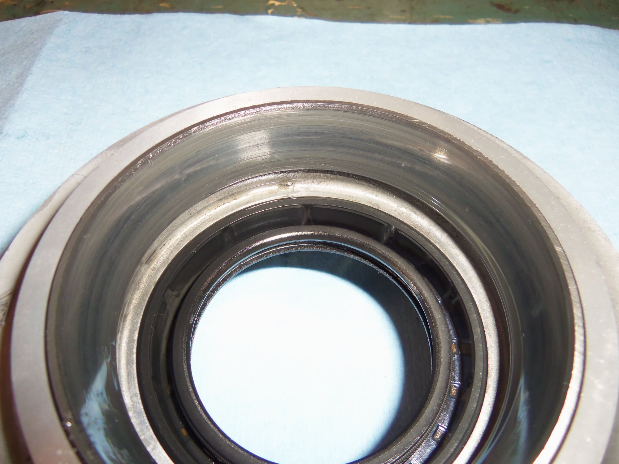
Speed pickup wheel with 8 embedded magnets, and differential side tapered roller bearing.
Ring gear teeth look good. I hope.
Spider and side gears look OK, as well.
Other side of differential showing locked ring gear bolts and tapered roller side bearing.
Differential casing unbolted from tail of transmission. Note magnetic drain plug sticking up through the bottom.
Transmission end of differential casing with metal shim still installed.
Metal shim removed.
One side of metal shim between differential casing and the separator plate.
Other side of shim.
Left side drive flange, showing sealing surface, and grey wear pattern of inner race of differential side bearing.
Right side drive flange, showing sealing surface, and grey wear pattern of inner race of differential side bearing.
Left side bearing cap with differential side bearing outer race. Wear on race looks OK, will not be changing bearings.
Right side bearing cap with differential bearing outer race.
Bearing side caps with outer sealing O-rings and spacer shims.
Bearing caps and their spacer shims.
Detail of one of the spacer shims.
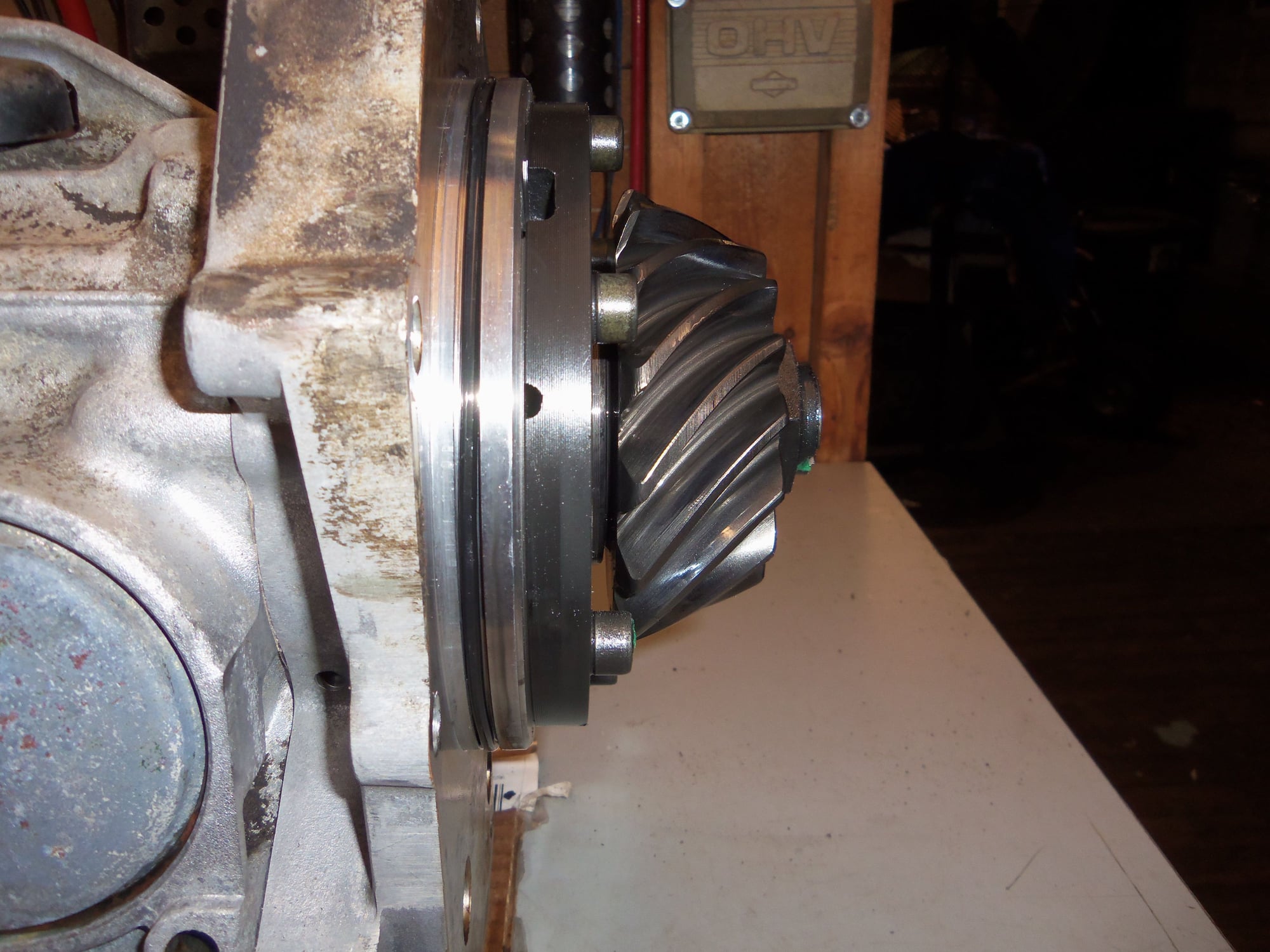
Pinion gear of differential still mounted on output shaft of transmission.
Side view of pinion gear, showing external sealing O-ring on the separator plate for sealing the differential casing. Note 'weep hole' in separator plate, in the shadow behind on of the bolt holes. Gear oil was seeping out of this hole.
Now that the differential was removed, I turned my attention back to the input side of the transmission. I removed the tape and trash bag...and sh*t myself. The K1 clutch assembly had fallen out!
Looking at the WSM Volume 3, I was able to figure out that the K1 clutch assembly was supposed to come out and this was not a bad thing. All the jostling of removing the transmission from the car had made the K1 clutch fall out.
I had no intention of removing anything from the front of the transmission, just to reinstall the front pump. Well...since the K1 clutch was out, I decided to have a good look-see inside.
This is what I SHOULD have seen when I removed the tape and trash bag from the front of the transmission.
Closer view of the K1 clutch assembly in situ.
This is what I saw, after removing the K1 clutch assembly after it fell out.
Let me add some clarification. This is not my first foray into an automatic transmission. However, I am NOT an expert. My day(night) job involves troubleshooting, disassembly, reassembly, and testing of small and large machinery at a metal stamping facility. I am used to taking things apart. So, before I went any further, I dug through the WSM Volume 3 to familiarize myself with the assembly of the A28 automatic. I approached this like an archaeological dig, as an onion. Carefully take it apart, layer by layer, and not screw anything up. I took photos, made notes of what went where and in what order. I do not fear the voodoo in an automatic, but it is to be respected.
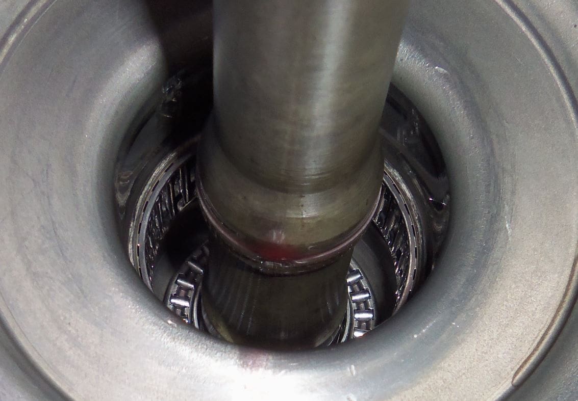
Note roller thrust (axial) bearing and radial drum needle bearings.
Roller thrust bearing, rotation washer, and shims. The order these were removed from the K1 clutch was noted. These were carefully removed with a tiny magnet on a stick.
Bore in K1 clutch where roller thrust bearing and washers sit.
Back side of K1 clutch assembly showing clutch plates and steels.
Interlaced clutch plates and steel plates. Steel plates have tabs on the outsides that mate up with grooves on the inside of the K1 clutch drum.
Gold/brown tabs on the clutch plates mate up with the corrugated metal structure round the input shaft of the transmission.
Corrugated metal structure around input shaft locates tabs on K1 clutch plates.
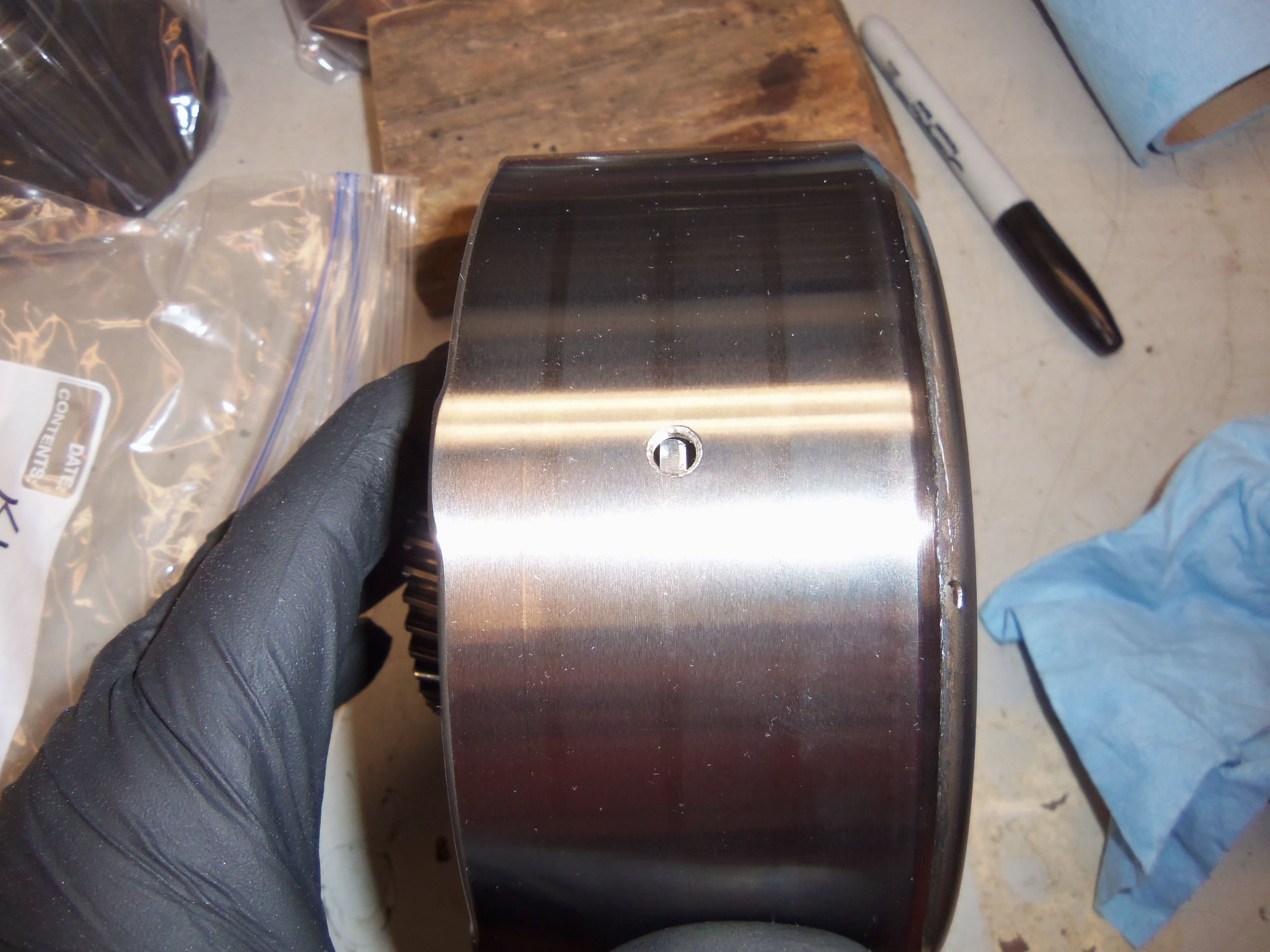
B1 brake band surface on outside of K1 clutch drum. Surface was smooth and defect free. Can faintly see wear patterns from brake band friction material.
After inspecting the K1 clutch assembly and removing the roller thrust bearing and washers, the assembly was drizzled with ATF, then put in a heavy plastic bag. It will not see the light of day until reassembly. I saw no need for further disassembly and/or deep cleaning. I felt solvents would do more harm than good here. All the clutch plates were still well soaked in ATF, the ATF was still bright red, and I saw no particulate matter or debris.
B1 brake band friction surfaces look surprisingly good, at least to me. Wear looks even, no hot spots or checking, or anything of that nature that I could see.
Same for the lower part of the B1 brake band.
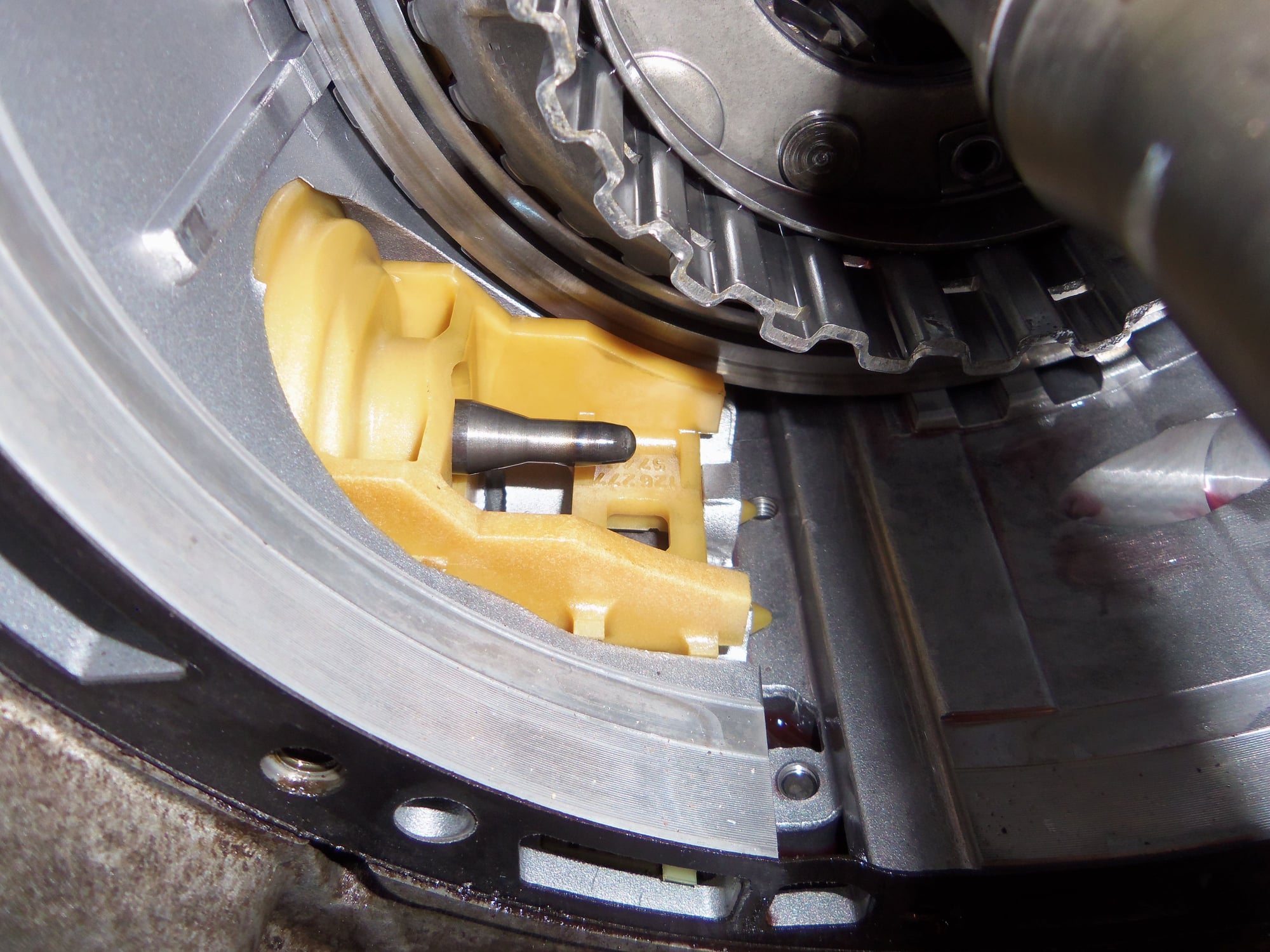
B1 brake band servo piston plastic guide.
I was pleased to see no real debris or such down here at the bottom.
B1 brake band pressure pin (anchor) at lower right.
B1 brake band pressure pin lives under this threaded plug. On 87+ transmissions, there is a pressure switch threaded into this plug.
Alright, a little transparency of tomfoolery here. I wanted to remove the B1 brake band to give it a good inspection. To do that, you have to remove the B1 apply servo and/or the B1 pressure pin. Servo cover has some no-kidding springs behind it, and would require a jig and some force. Cover over B1 pressure pin should just unscrew right now. Would it now...
At this particular moment, my metric impact hex bits were at work. I didn't want to wait two days to be back at work. I wanted to disassemble this NOW. Also, work is a 35 minute drive away. Not going for a socket. So...I decided to make something. It worked eventually, but mistakes were made.
First attempt at building a tool from a 1/2" hex coupling nut, ground down to approximately 12mm.
Tap tool into plug, apply torque with wrench. Fail. Plug did not budge.
If some force is not enough, go right to too much force. Go right to FAIL!
Impact torque and resistance of plug were too much for my 'tool'. Rounded it right off. Granted, this coupling nut was only grade 5, and in no way shape or form impact rated. I was not exactly surprised this failed.
Sacrificed a 1/2" hex bit socket by grinding it down to approximately 12mm.
Tap socket into plug, carefully apply UGH with impact, plug comes out.
Plug removed, B1 brake band pressure pin in situ.
B1 brake band pressure pin and threaded plug. Note lack of crush washer on plug. Oil is sealed in by the two O-rings on the body of the assembly.
Bore in transmission casing for B1 brake band pressure pin.
Successfully removed B1 brake band.
Closer look at friction material on B1 brake band. One of my experts informed me that the part number rarely wears off, except in the case of extreme wear.
B1 brake band servo piston and plastic guide.
I have read several posts on Rennlist and seen references to the fact that the B3 clutch plates are a known wear item on the A28(Mercedes 722.3) automatic. They are usually the first to wear, and give indications of that by delayed engagement of reverse gear. To my recollection, the Red Witch had no hesitation going into reverse. However, since I was this far in, it would be foolish not to inspect the B3 clutch plates.
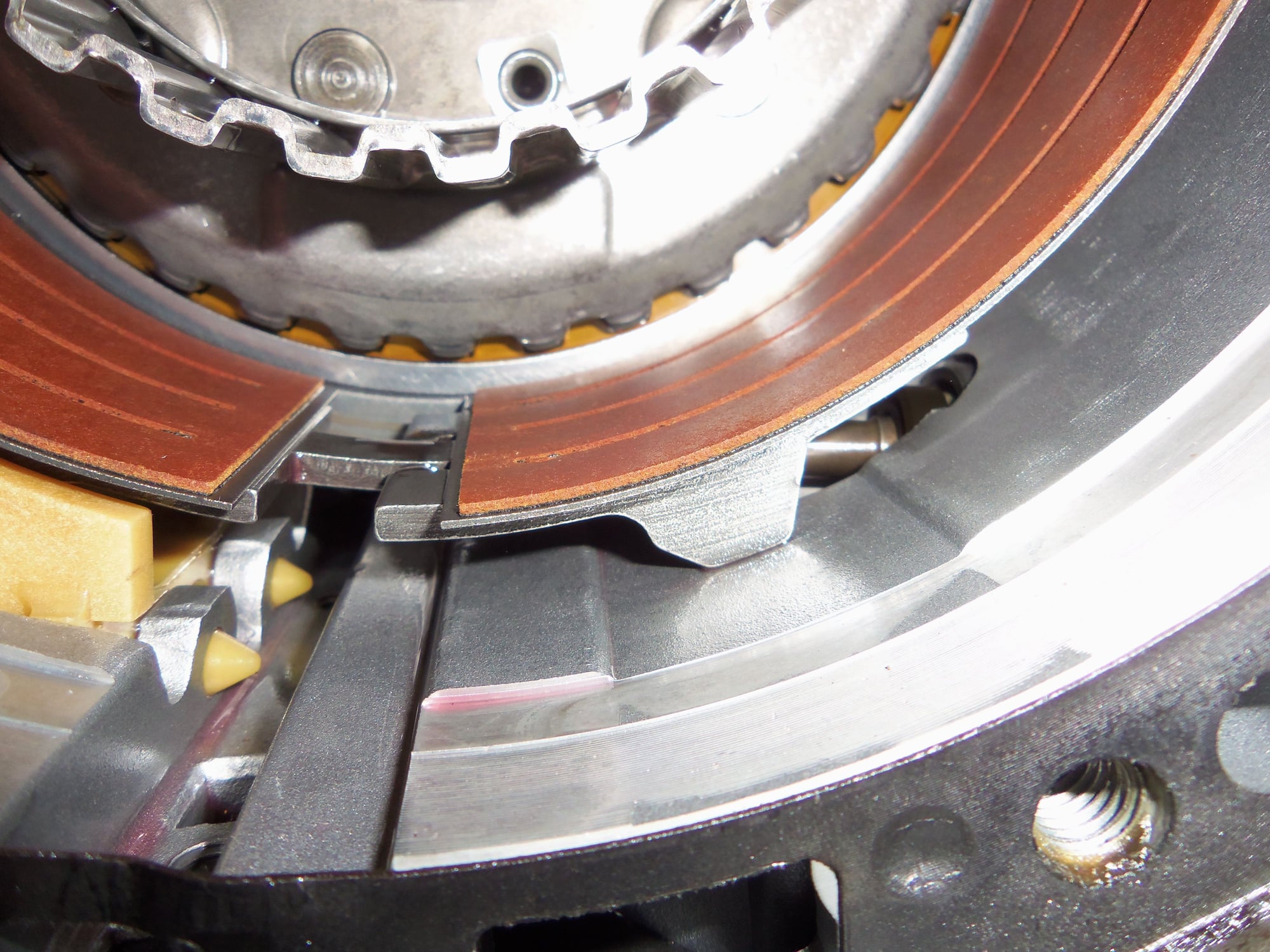
Look closely between the B1 brake band and the corrugated metal structure around the input shaft, you can see the B3 clutch plates peeking out.
With the B1 brake band out of the way, you can see the outer shim for the B3 clutch pack.
At the top of the splines in the case for the steel plates of the B3 clutch, you can see the damping spring put onto three of the splines.
First B3 clutch steel at left, shim at right. As per WSM Volume 3, this outer steel is 2.8mm thick.
First B3 clutch plate out of the pack after the outer steel. Initial inspection says plate looks good. Because I don't know what I am looking at...
Both steel and clutch plate surfaces look good, no hot spotting or localized wear.
I got excited because the Mercedes part numbers were still quite visible on the clutch plate. Expert took the wind out of my sails saying those numbers don't wear off except in cases of extreme wear.
I did note some erosion of the friction material at the outer circumference of this plate. I did not fully understand the implications of this...
More erosion on another plate.
More steels, another plate. The intermediate steels are supposed to be 2.3mm, as per WSM Volume 3.
Inside steel plate. It is flat on this side, to engage the inside most clutch plate. This steel is supposed to be 7.7mm thick, as per WSM Volume 3. This steel is quite hefty compared to the others.
Inside steel plate, It is beveled on this side, which faces into the K2 drum.
All the B3 steels and clutch plates removed. You can now see the front of the K2 clutch drum. I did not remove that.
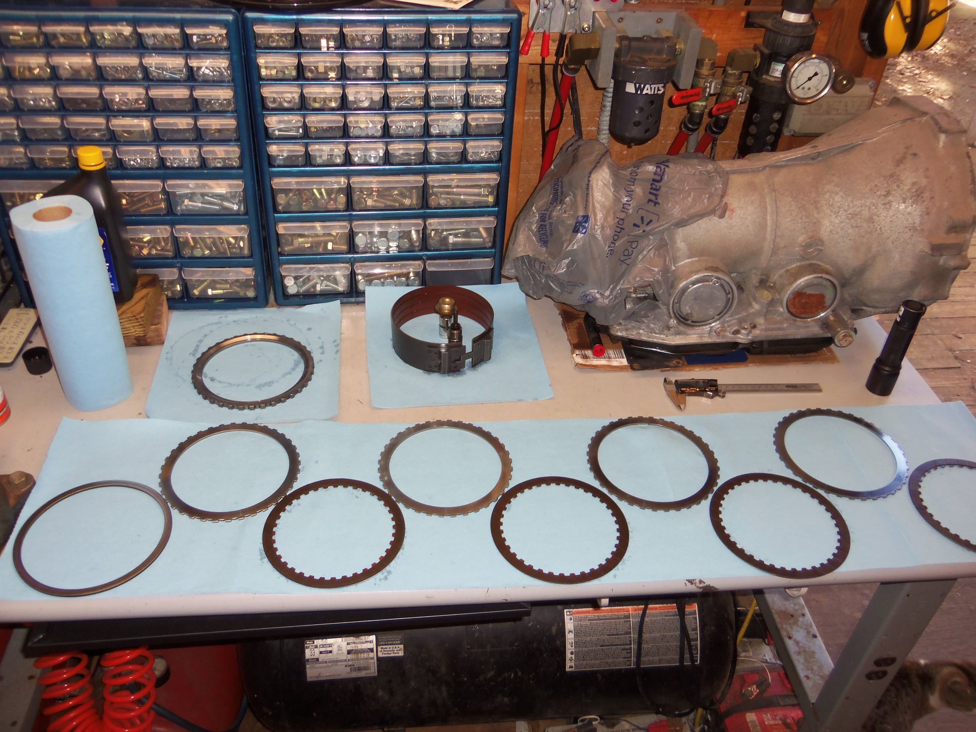
All the B3 clutch plates and steels laid out in the correct order AND orientation. I put the clutch plates and steels back in facing the same way they came out. Meaning the face of each steel and clutch touched the same ones as it came out.
Applying ATF to the clutch plates prior to reassembly.
Overall, the B3 clutch plates and steels looked great! To me.
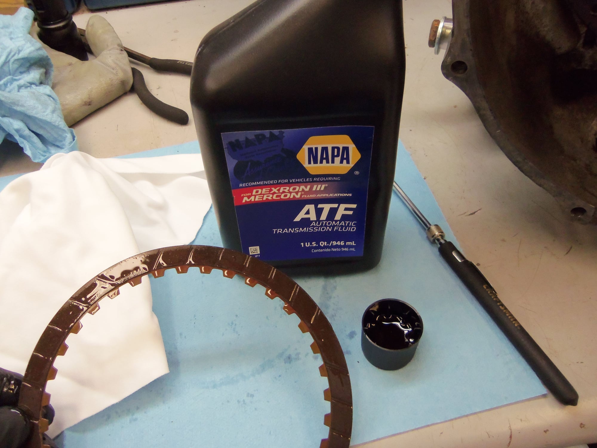
All the clutch plates measured right at specification of 2.1mm as per WSM Volume 3:
plate 1: 2.09mm
plate 2: 2.11mm
plate 3: 2.09mm
plate 4: 2.10mm
So, I lubricated the clutch plates with NAPA Dexron III ATF and reassembled the B3 clutch EXACTLY as I found it.
Shortly after, my experts looked at the photos and raised the red flag.
While the plate thickness was great, the erosion of the friction material from the outer circumference was a BAD THING! Once the plates start sloughing off friction material, they don't stop. The Red Witch did not have problems with the B3 clutch or reverse gear, but she would soon enough.
New Mercedes B3 clutch plates were promptly ordered.
New plates measured: 2.14mm, 2.14mm, 2.07mm, and 2.13mm
Installation was straight forward. I soaked them in fresh ATF, then reassembled the B3 clutch with the new plates.
One less thing to worry about.
New Mercedes 126 272 09 25 clutch plates.
Plates soaking in ATF in a zip-lock bag for a few hours.

 03-07-2018, 10:37 PM


 ). I didn�t WANT to take her apart. I resisted common lore in the 928 world. Yet, everything I said I WOULDN�T do, I DID. Just in the wrong order.