When you click on links to various merchants on this site and make a purchase, this can result in this site earning a commission. Affiliate programs and affiliations include, but are not limited to, the eBay Partner Network.
All I could do is shake my head, close it, and hope that no one that was ever going to do any of this work never read it.
There's so much misinformation, mixing of pieces an S4 has, which an S3 doesn't have (and visa versa) I was hoping someone would either erase the entire thing, or go back and correct all the mistakes.
Greg,
These threads are written by folks who on their own admission, have no experience of undertaking such and thus rely on others who have been through that learning curve to help correct any misunderstandings or omissions.
The WSM's, whilst essential tools, are not written for DIY enthusiasts and to say the least can be somewhat confusing mostly by what they do not say rather than what they do say and the section that demonstrates 32 valve cam replacement is probably the worst example I have come across to date but that did not stop me from figuring it out [or so I believe].
These threads only work if those with more knowledge chip in and then ultimately folks like yourself [with definitive knowledge] polish things off. That you take your valuable time to offer such insights is truly appreciated.
When the above takes place these threads have tremendous value even if they are repeats of previous similar iterations.
Your pictures are good. I love the foam pieces you made to plug the oil return galleys. You're doing pretty good. Good idea to change the chains at this mileage, especially since you are already there. The cams are not like "glass" brittle. They are cast iron and cast iron doesn't flex much. As long as they come out (and go back in) square (and don't get hung up in the front where the "thrust" surfaces are), you will be fine. Leave the lifters alone.....unless you plan on taking them completely part (they do come apart) and ultrasonically cleaning out the "inner sludge trap" multiple times.
This stuck out and will confuse the heck out of future readers:
According to various threads I had read, S3 tensioners were spring loaded, S4's were not.
This means I am scrooged. I have to get a set of used S4 tensioners, new pads, and figure out what to do about the oil lines.
This put a serious crimp in my happiness. Don't get me wrong, I am going to to this, just didn't want to have to reinvent the wheel. I am not going to be this far in and not replace the tensioner pads.
S4 tensioners are also spring loaded.....as you have figured out.
OK, I can live with that. I have gone back to post #1 and edited it with a bold correction in red. Hopefully that will prevent any confusion for future readers.
As for the lifters, I am going to leave them where they stay.
The Red Witch is not a sludge-monster. The oil pan, crankcase, and heads are very clean. I will leave whatever crud is in the lifters, in the lifters. I am not doing a full rebuild, just replacing chains and pads. At this point, the time and effort required to remove, organize, disassemble, ultrasonically clean multiple times, reassemble, lubricate, and reinstall 32 lifters can be better spent elsewhere on the Red Witch.
However, would it be a good idea to run a bottle of Swepco 502 through the oil for initial start up and running in? I am running 9 quarts of sacrificial dino oil and a new Mann oil filter for the start up and running in of this engine. I plan on running this oil for a couple hundred miles to flush out anything I have disturbed while working on the engine. Then, a proper fill of Mobil 1 15W-50 and a new Mann oil filter.
Save your money and just get a picture of the cam profile tool with a ruler next to it. Then printed it and resize it until the ruler is accurate. As for the cam hold down tool, not needed, just loosed the caps slowly and make sure to do it in several steps.
Thank you for the idea! However, I already have the cam tools. I bought them awhile ago from a Rennlister who no longer needed them.
These threads are written by folks who on their own admission, have no experience of undertaking such and thus rely on others who have been through that learning curve to help correct any misunderstandings or omissions.
The WSM's, whilst essential tools, are not written for DIY enthusiasts and to say the least can be somewhat confusing mostly by what they do not say rather than what they do say and the section that demonstrates 32 valve cam replacement is probably the worst example I have come across to date but that did not stop me from figuring it out [or so I believe].
These threads only work if those with more knowledge chip in and then ultimately folks like yourself [with definitive knowledge] polish things off. That you take your valuable time to offer such insights is truly appreciated.
When the above takes place these threads have tremendous value even if they are repeats of previous similar iterations.
Thank you, FredR. I research my work as much as I can, but ultimately, I am making this up as I go.
Greg, question: Is the round seal on the end plug cap replaceable?
The Red Witch originally came with cam end plug seals:
A 928 105 319 02 sealing ring
A 944 105 259 00 cover
In April 2016, as part of the pre-purchasing service, I had these seals replaced. Upated parts were installed:
928 105 215 00 cover
928 105 201 00 support
I am replacing all 6 seals again just because. I am concerned that they will be damaged upon removal.
Is sealing ring A 928 105 319 02 appropriate to install on cover 928 105 215 00? Meaning can I get new seals and install on my slightly old covers?
Or do I just install new covers and be done with it?
Never mind. I figured it out as soon as I got the passsenger's side front cam bridge off. I had envisioned the end plug seals being a ring type seal on a plastic carrier.
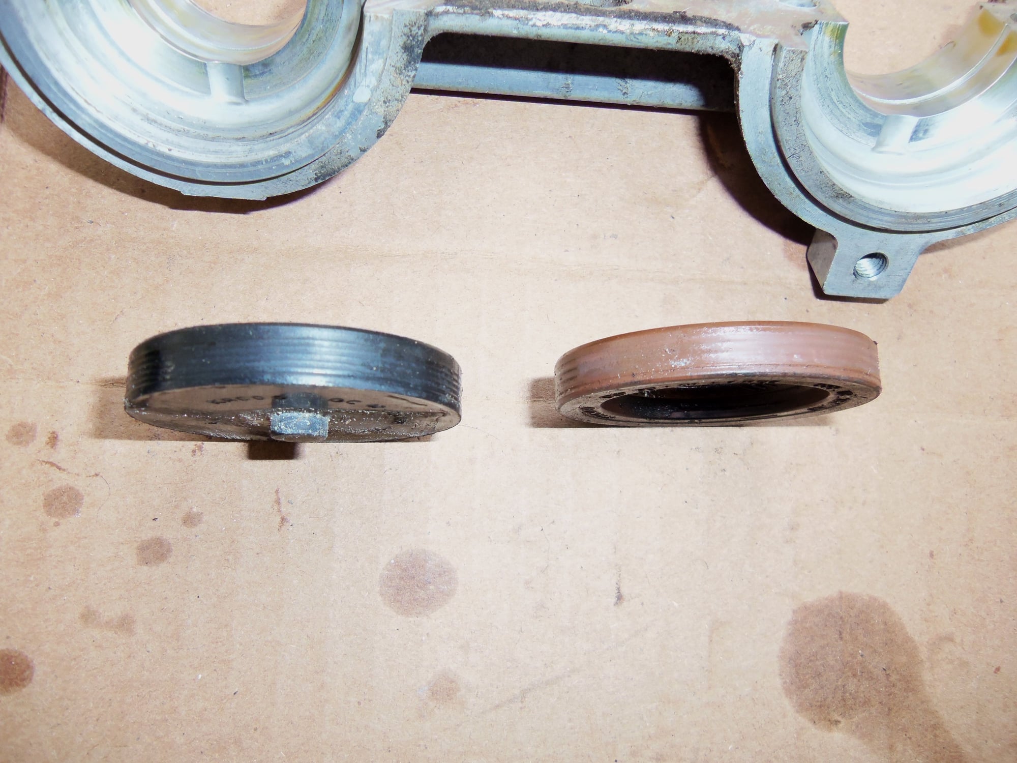
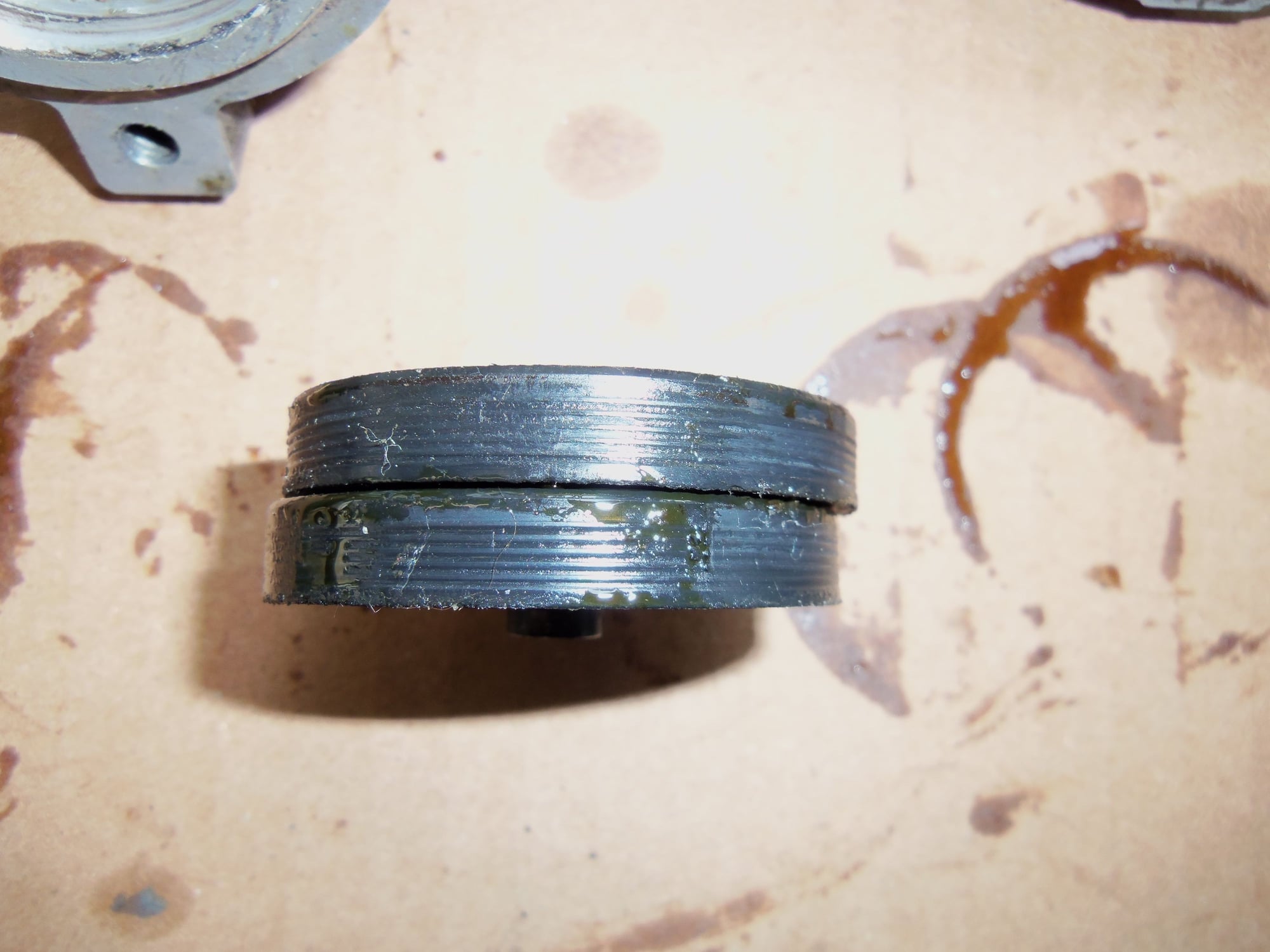
I was wrong. The updated two piece seals are a rubber coated metal cup. The profile is the same as the cam seal. Makes perfect sense now. These are a one time use.
I am ordering 6 new covers.
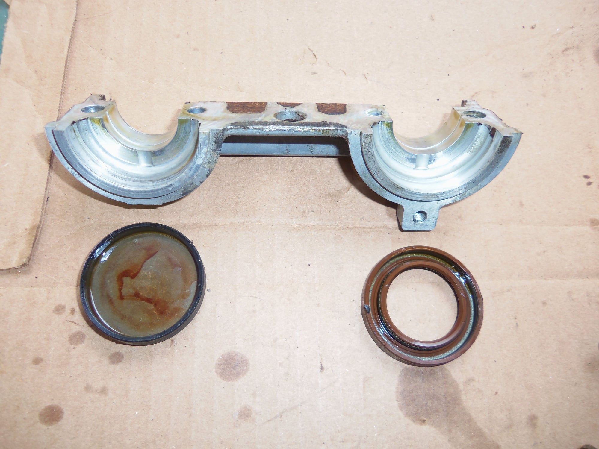
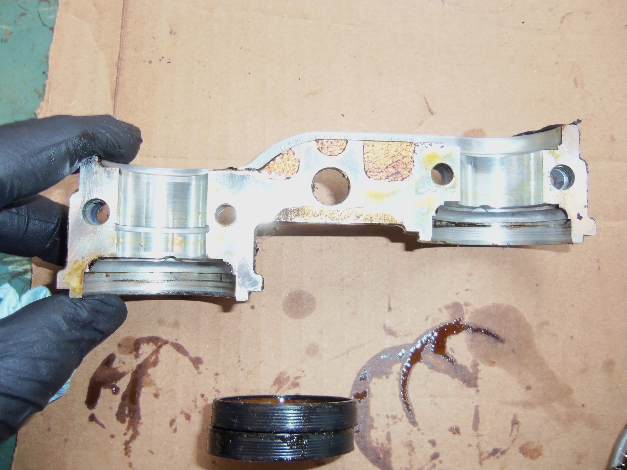
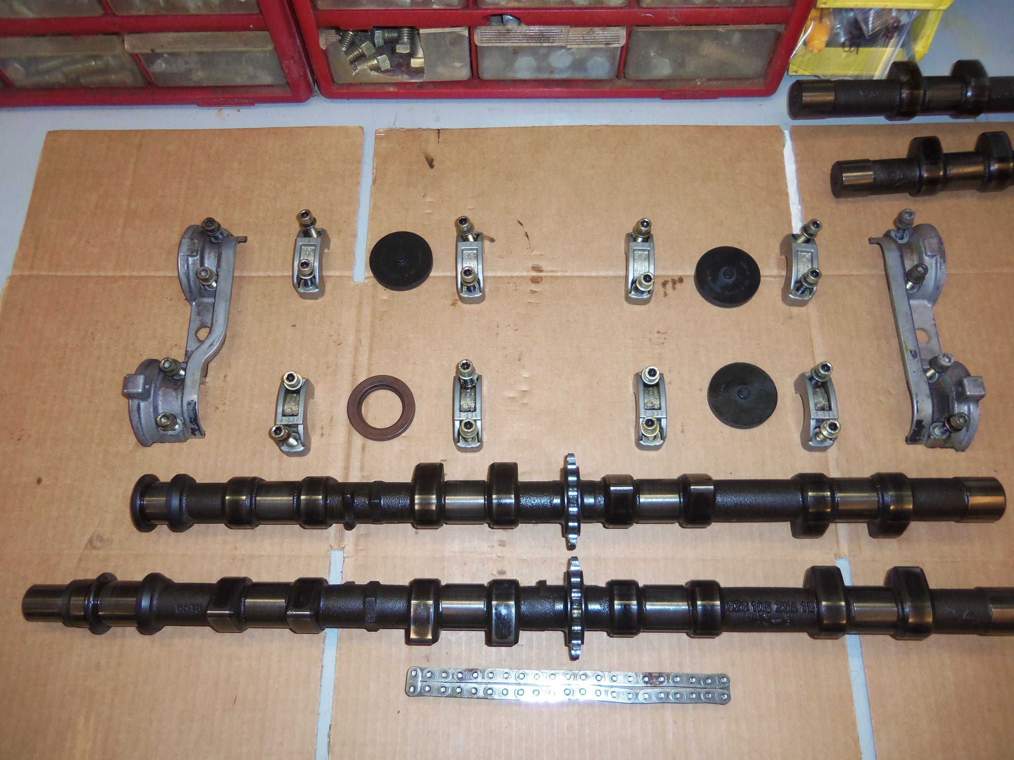
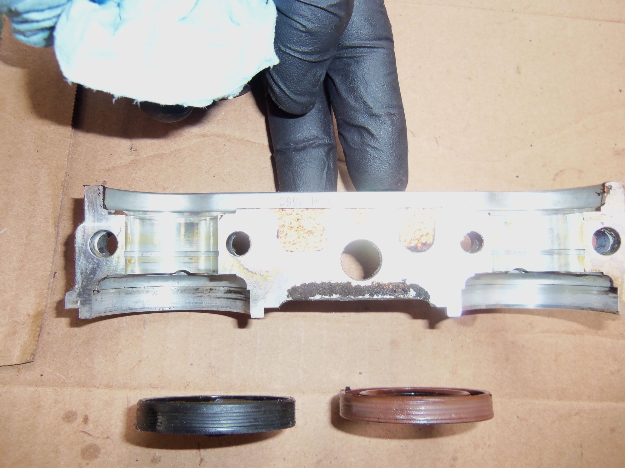
Front cam bridge and seals.
End plug seal is a rubber coated metal cup, not a plastic carrier with a ring seal as I had thought.
Can see the cup shape from the inside.
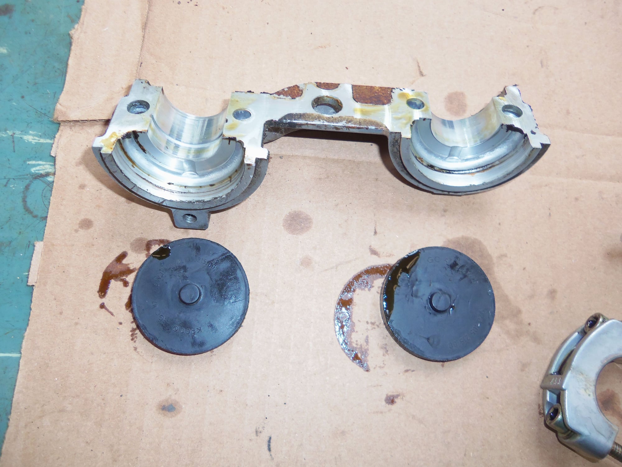
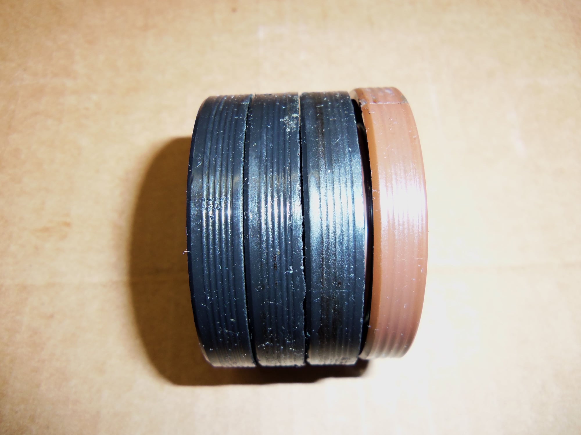
Rear cam bridge and seals.
Same profile on plug seals as cam seals. Definitely one time use.
These threads are written by folks who on their own admission, have no experience of undertaking such and thus rely on others who have been through that learning curve to help correct any misunderstandings or omissions.
The WSM's, whilst essential tools, are not written for DIY enthusiasts and to say the least can be somewhat confusing mostly by what they do not say rather than what they do say and the section that demonstrates 32 valve cam replacement is probably the worst example I have come across to date but that did not stop me from figuring it out [or so I believe].
These threads only work if those with more knowledge chip in and then ultimately folks like yourself [with definitive knowledge] polish things off. That you take your valuable time to offer such insights is truly appreciated.
When the above takes place these threads have tremendous value even if they are repeats of previous similar iterations.
I think you might be missing my point.
I agree that threads can be good "tools". However, when they have lots of misinformation and mistakes, i wonder what their value really is.
It would be great if people would go back into these threads and correct their mistakes and misinformation, however this rarely occurs.
When this job is done, because of the plentiful pictures, this thread could be a good thread....with some cleaning and removal of misinformation.
As far as the WSM is concerned about this job....I'd agree that it is a bit "wordy".....and perhaps there was something lost when it was translated from German to English, but if one follows the process exactly as written, it works perfectly.
And once one figures it out, it's super easy:
1. Install dial indicator, parallel with the valve stem, on intake lifter of cylinder #1, when the intake lobe is facing up (towards the sky.)
2. Zero indicator
#. Rotate engine to 20 degrees after TDC. Read indicator. Compare reading to the desired value in the WSM for your engine.
4, Correct as needed until the reading obtained is the same as in the WSM.
Repeat for cylinder #6.
NOTE! Because various camshafts have vague or incorrect markings of where the chain should align with the teeth, it is suggested that the exhaust cam also be checked and compared to the opening events as described in the WSM. (This is extremely important with all '85/'86 cams and GT cams.) This requires a degree wheel.....or one of my ATI dampers.
An excellent way to quickly accomplish this task is to first set the exhaust cam using Porken's cam timing tool....and then check the intake cam per the WSM. It is not uncommon to find the intake cam off one tooth on the vehicles mentioned above!
Semi-retired, as of Feb 1, 2023.
The days of free technical advice are over.
Free consultations will no longer be available.
Will still be in the shop, isolated and exclusively working on project cars, developmental work and products, engines and transmissions.
Have fun with your 928's people!
I agree that threads can be good "tools". However, when they have lots of misinformation and mistakes, i wonder what their value really is.
It would be great if people would go back into these threads and correct their mistakes and misinformation, however this rarely occurs.
When this job is done, because of the plentiful pictures, this thread could be a good thread....with some cleaning and removal of misinformation.
As far as the WSM is concerned about this job....I'd agree that it is a bit "wordy".....and perhaps there was something lost when it was translated from German to English, but if one follows the process exactly as written, it works perfectly.
And once one figures it out, it's super easy:
1. Install dial indicator, parallel with the valve stem, on intake lifter of cylinder #1, when the intake lobe is facing up (towards the sky.)
2. Zero indicator
#. Rotate engine to 20 degrees after TDC. Read indicator. Compare reading to the desired value in the WSM for your engine.
4, Correct as needed until the reading obtained is the same as in the WSM.
Repeat for cylinder #6.
NOTE! Because various camshafts have vague or incorrect markings of where the chain should align with the teeth, it is suggested that the exhaust cam also be checked and compared to the opening events as described in the WSM. (This is extremely important with all '85/'86 cams and GT cams.) This requires a degree wheel.....or one of my ATI dampers.
An excellent way to quickly accomplish this task is to first set the exhaust cam using Porken's cam timing tool....and then check the intake cam per the WSM. It is not uncommon to find the intake cam off one tooth on the vehicles mentioned above!
Corrections are in progress.
I cannot take credit for the idea of the foam blocks in the oil drains. I completely stole that from another Rennlister while searching threads on replacing tensioner pads.
Also in progress are negotiations to borrow the factory tools I need to finish this job. I will see how close my cams are to spec.
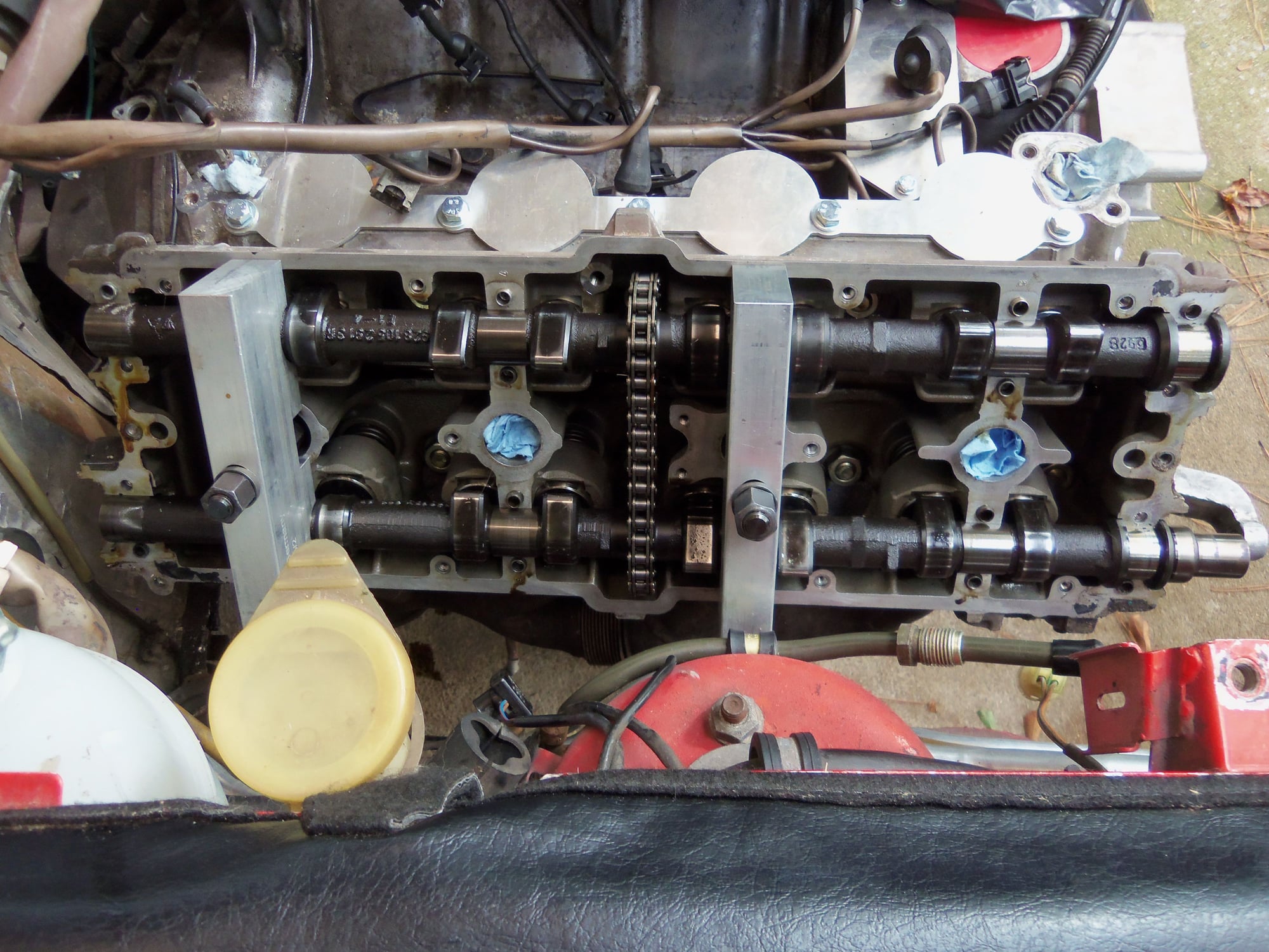
Alright, my vacation is over. I have to go back to work tomorrow night. However, I achieved my goal. The cams are out!
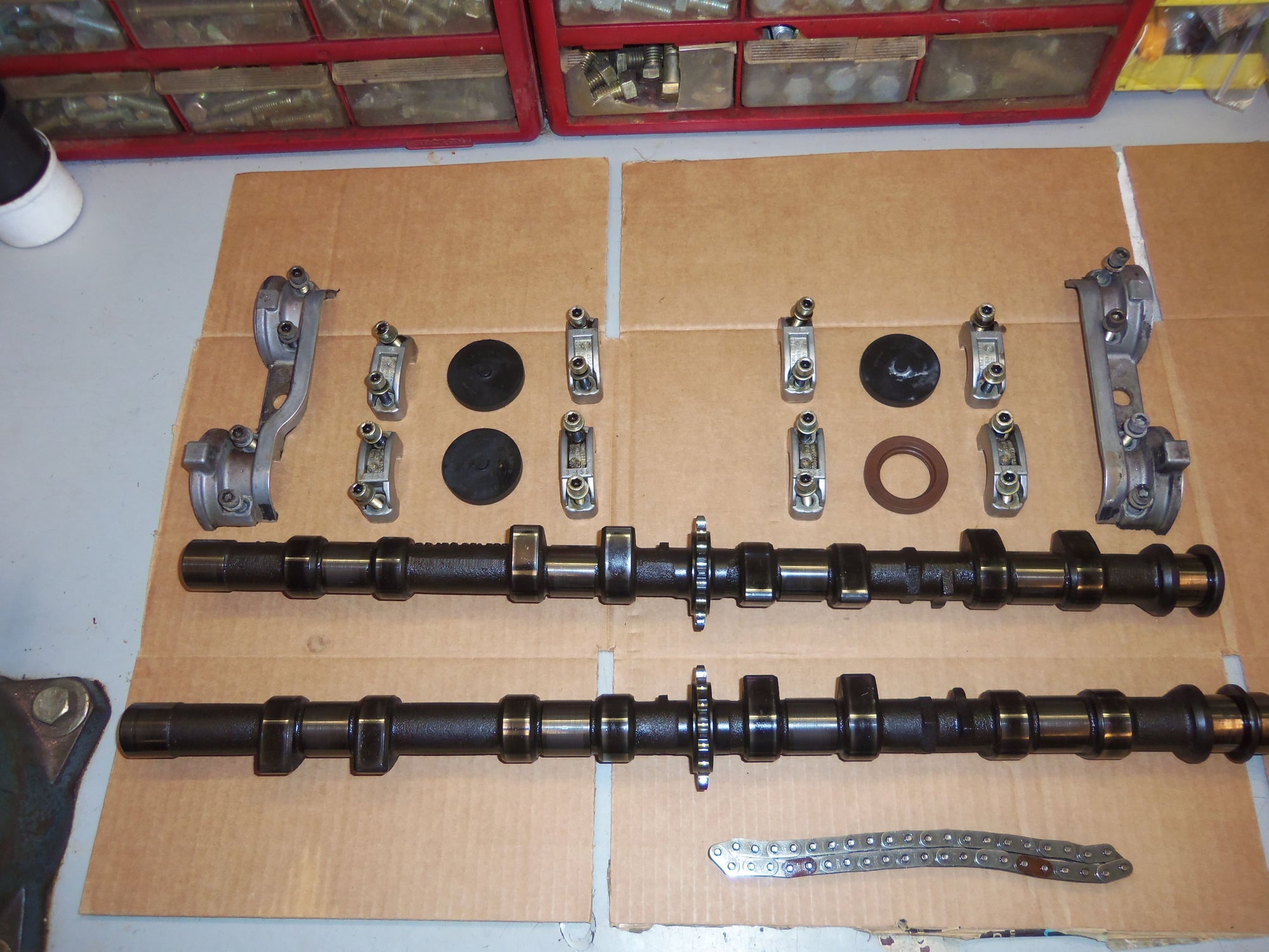
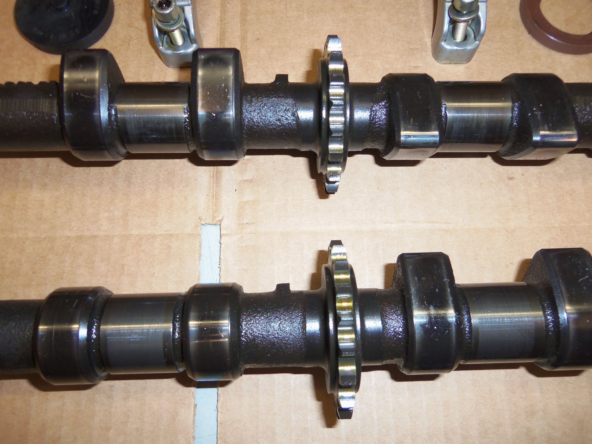
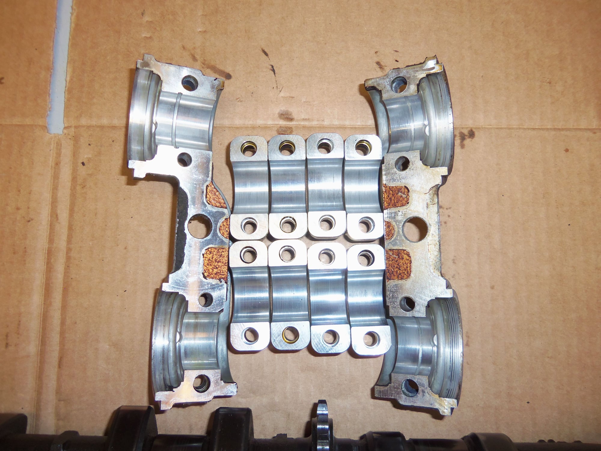
Passenger's side cams, chain, bearing caps, bearing bridges, cam seals, and end plug seals.
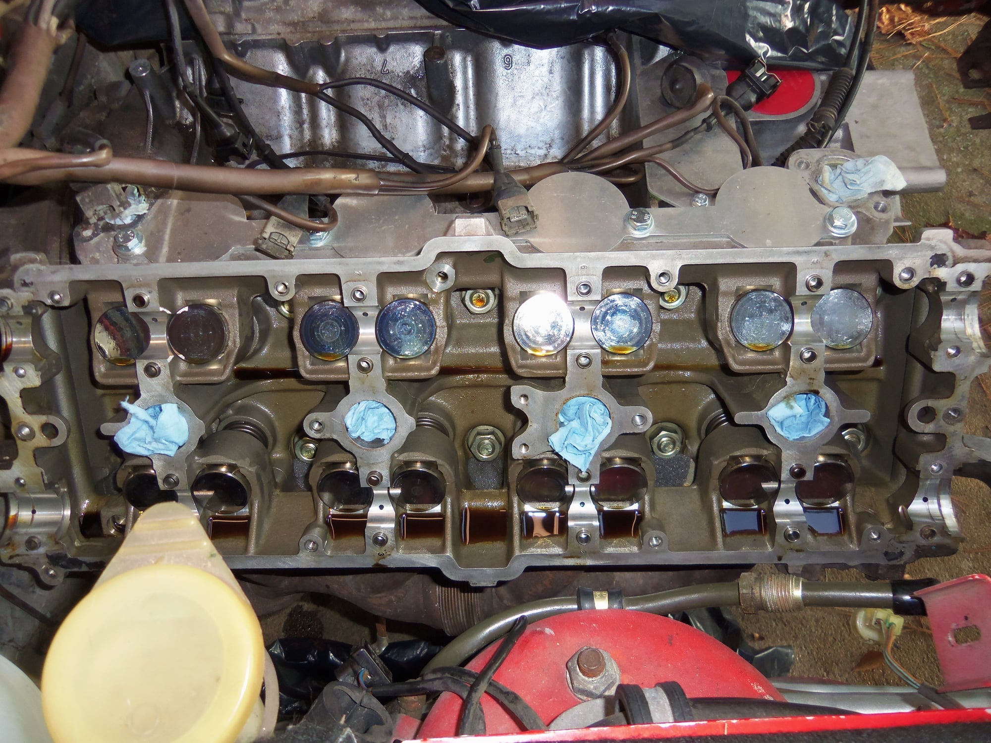
Passenger's side cylinder head.
Driver's side cams, chain, bearing caps, bearing bridges, cam seals, and end plug seals.
Driver's side cylinder head.
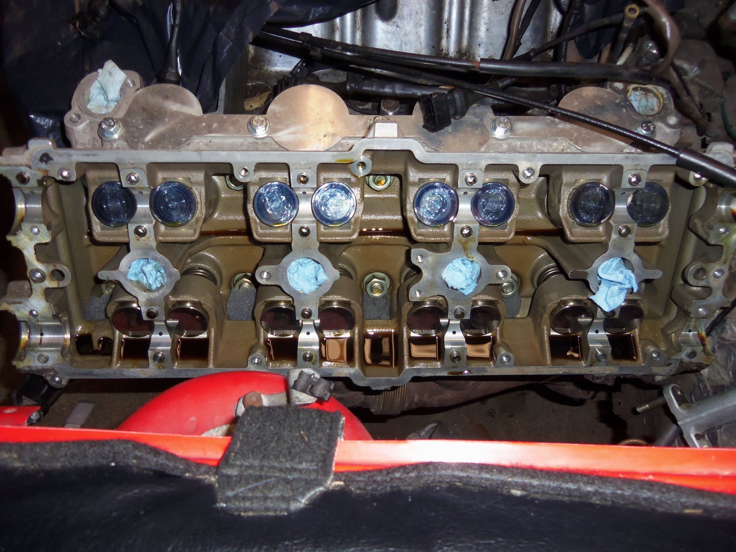
I started with the passenger's side. I whacked each bearing cap bolt head with a ball pein hammer against a small brass pipe plug. Best I could do give the limited working conditions.
On this note, D*mn its tight in this engine compartment! Even with ALL the stuff I have removed, this was a pain in the ***. I'd almost say I should have pulled the engine. But I won't.
Anyway, I used a tight fitting 5mm hex L-key and a length of copper 1/4" NPT pipe as a small cheater bar to break each bearing cap bolt loose. After it was broke loose, I tightened each bolt by hand.
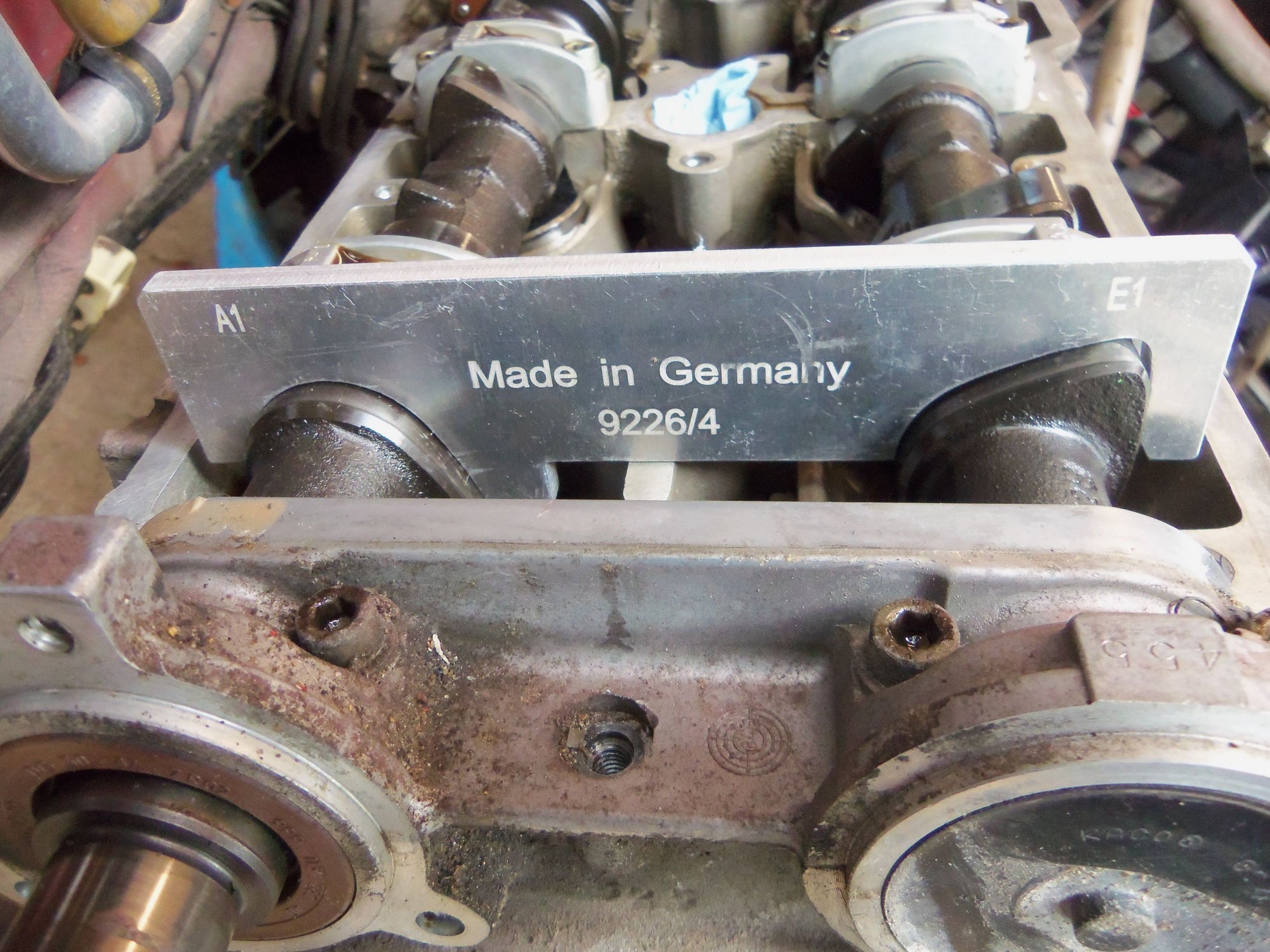
For giggles, I fitted the 9226/4 profile gauge on the first set of intake and exhaust lobes. It fit very well. I took that as a good sign.
Profile gauge fits very well on first lobes on passenger's side camshafts.
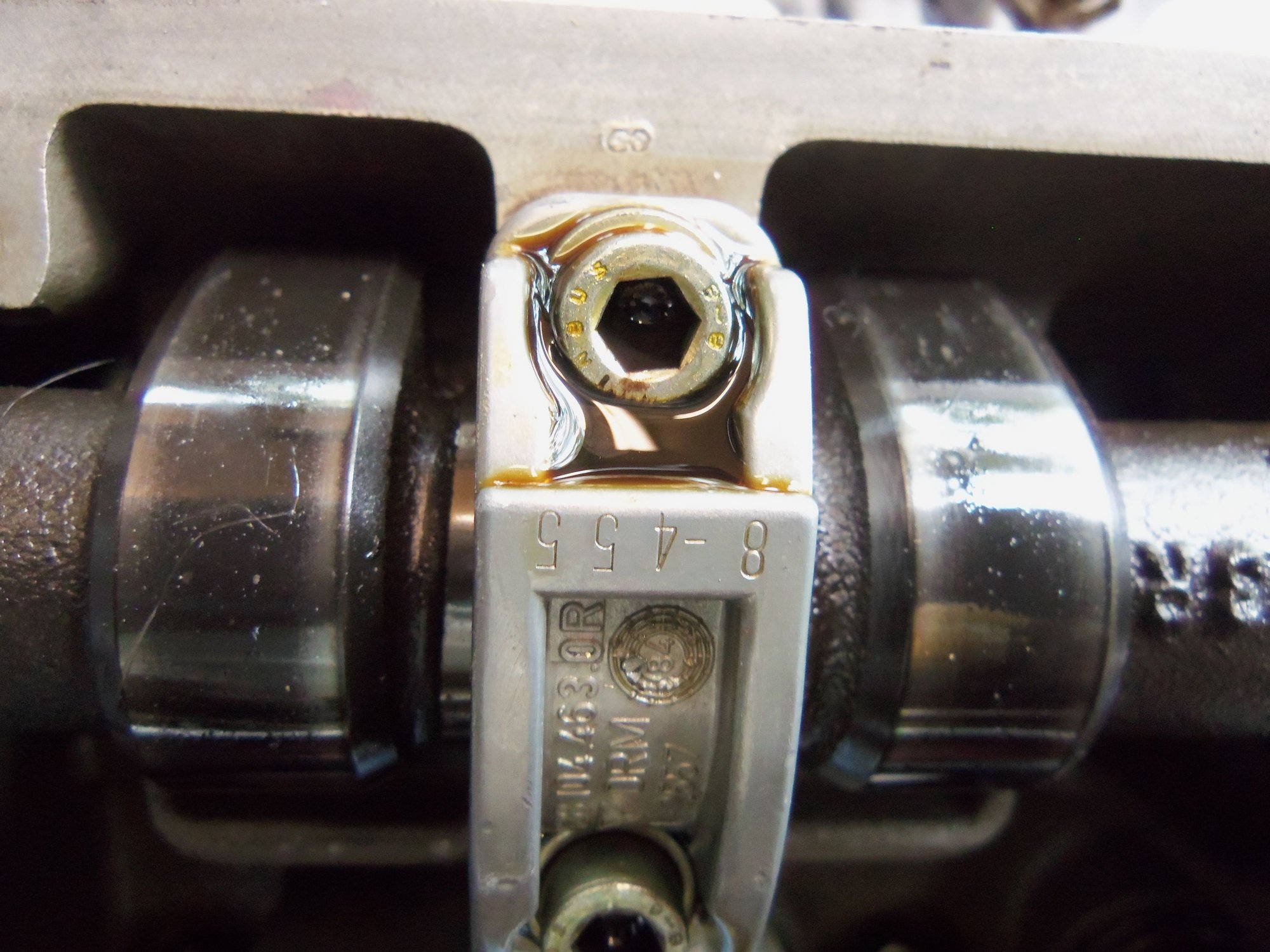
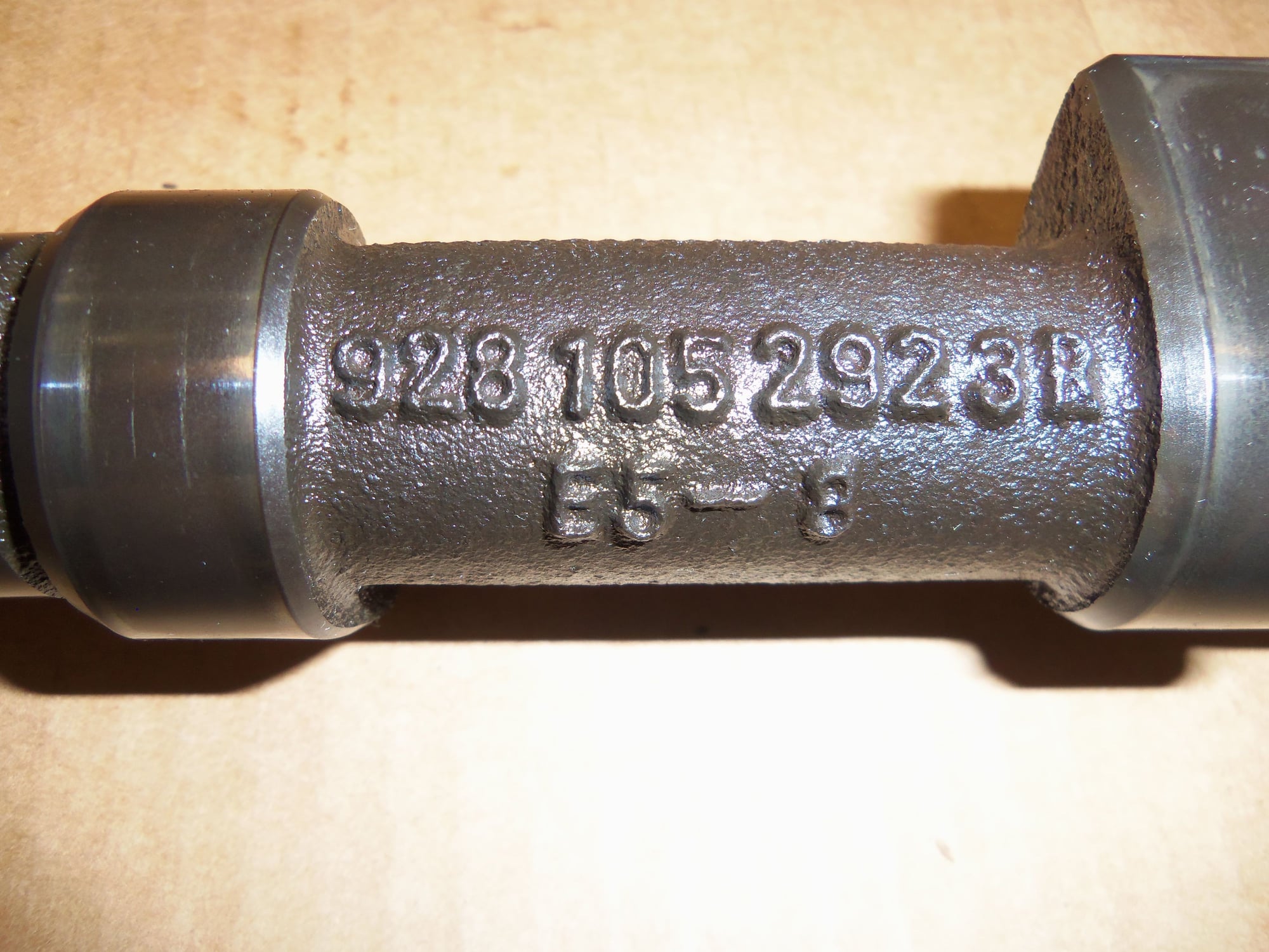
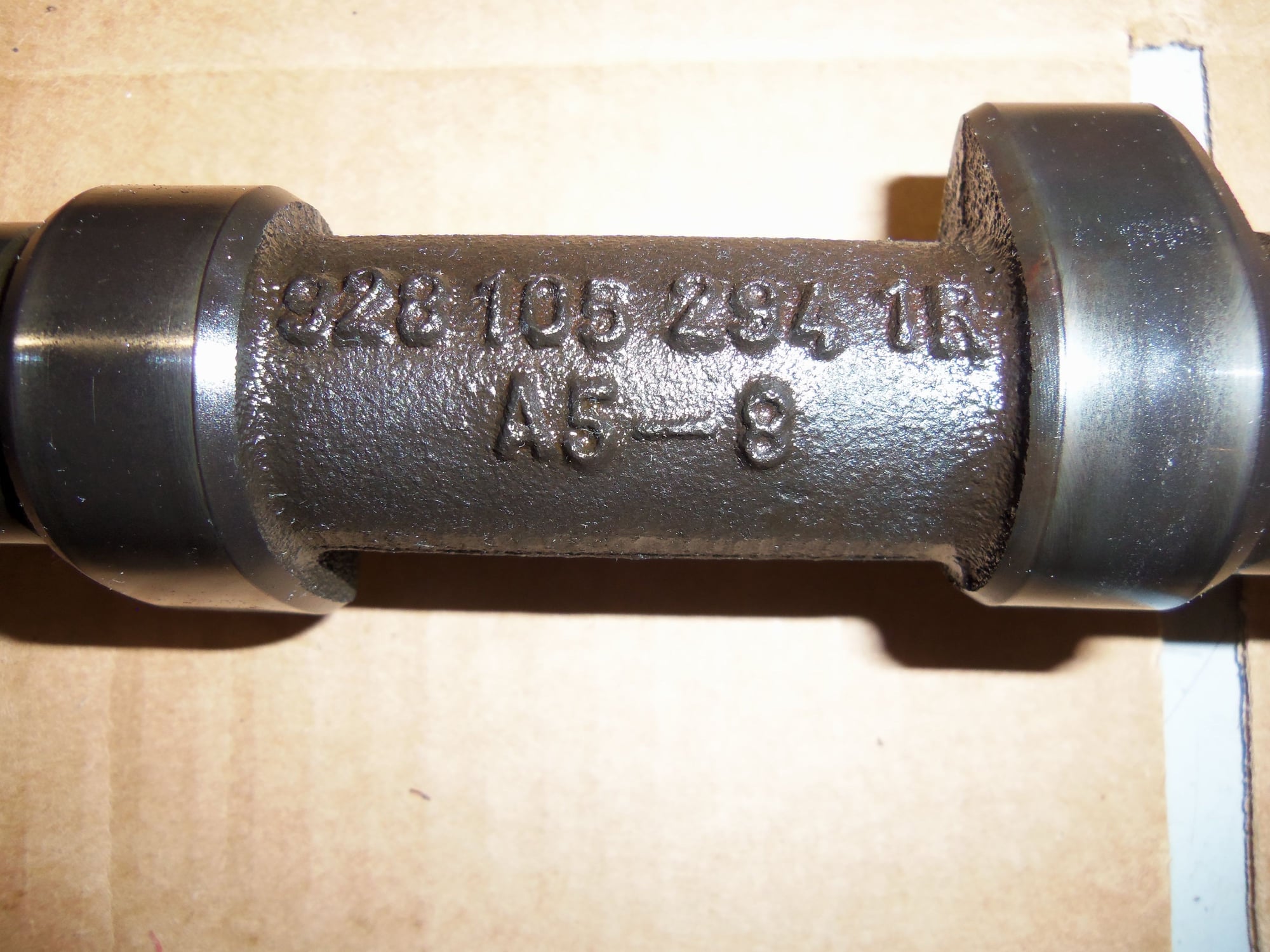
As per the WSM, I removed the #'s 6/2 and 8/4 bearing caps. NOTE: This refers to the stamped ID numbers on each cam bearing cap, not the cylinder number.
Example of cam bearing cap numbering. Note the -8 after the 455, and the 8 stamped into the sealing rail of the head.
I found the best method to remove the bearing caps from the alignment dowels was to gently tap the cap on each side, avoiding the cam lobes, with a small brass hammer. Once the cap was a little lose, I was able to gently rock it side to side, and then up, using a small set of Knipex pliers.
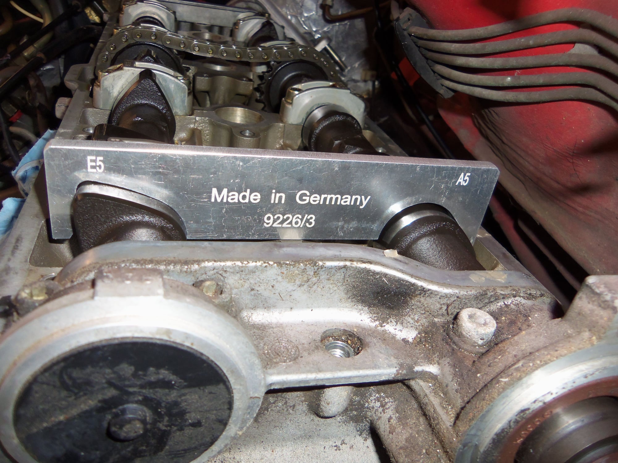
I was able to install the 9226/1 stud in the spark plug hole and 9228/2 bridge with no problem across the 5/4 cam journals.
I had a helluva time installing it across the 6/2 journals. The edge of the bridge got hung on the fuel and AC lines along the inner fender, around the front shock tower. I ended up fitting the stud into the bridge, then working it all into place. I had to turn the stud in by hand, then tighten it with a thin 19mm wrench by slightly lifting the bridge for clearance.
It almost might have been better just to slowly loosen all caps slightly at a time as I had been advised. Might have been.
With the cam tool bridges set in place, I removed the rest of the bearing caps. The end bridges gave me trouble. A combination of gently tapping on the front lip and inside the sealing rail on the back side of the front bridge succeeded in freeing it. Too bad it was hung on the cam seal. I threaded a 6mm bolt into the top cam sprocket back plate mounting hole in the top of the cam bridge, above the nose of the exhaust cam. With the copper pipe as a soft spacer, I pried up against the bolt with a wrench. This freed the cam seal from the bearing bridge. The nose of the cam was undamaged.
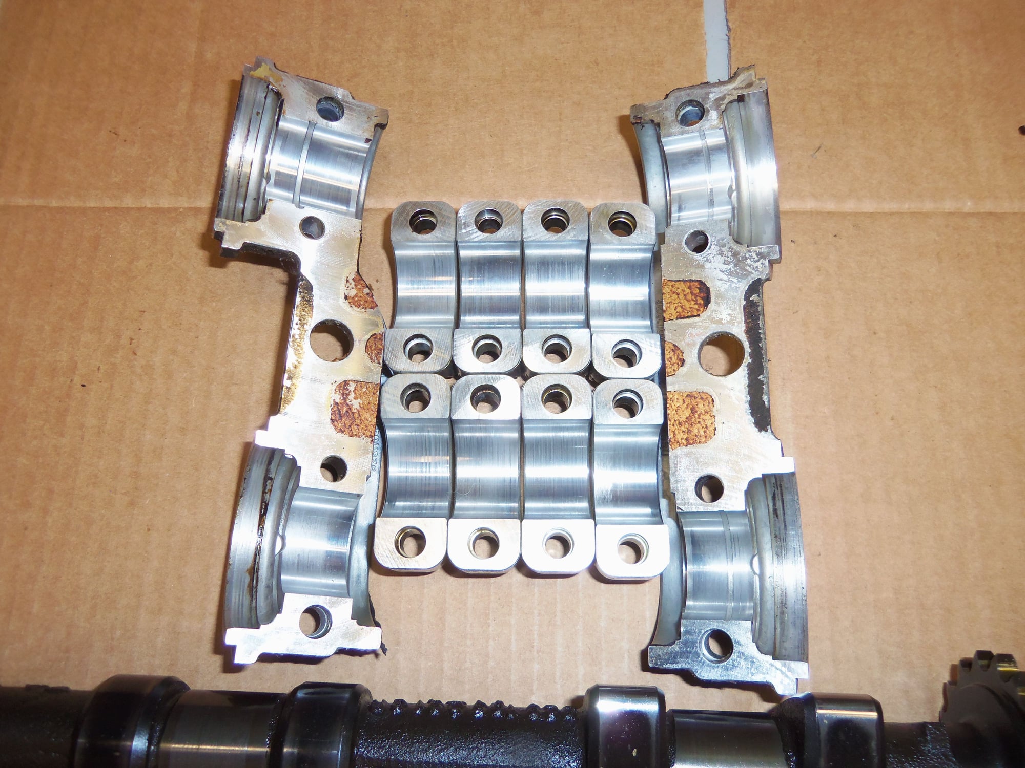
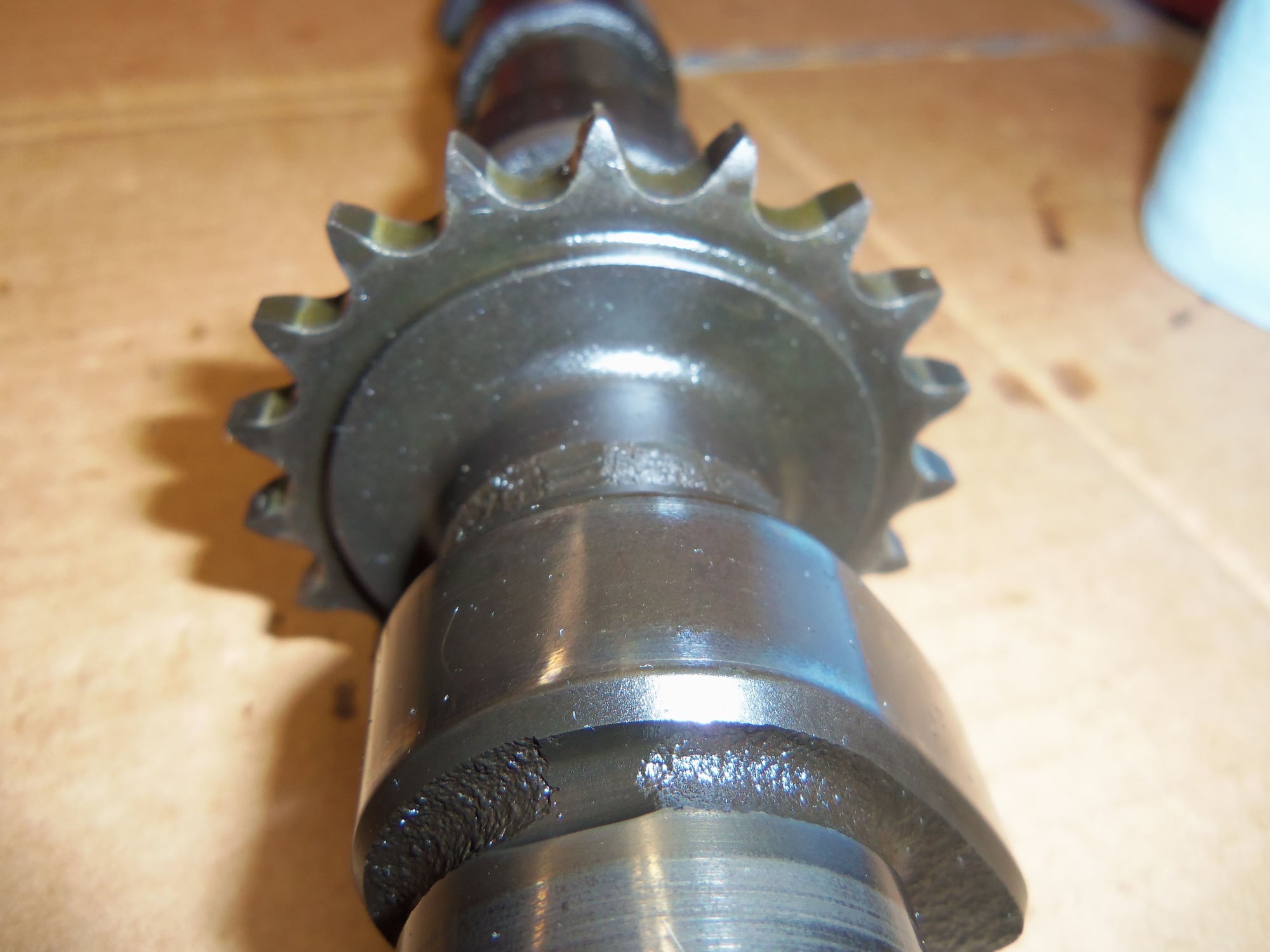
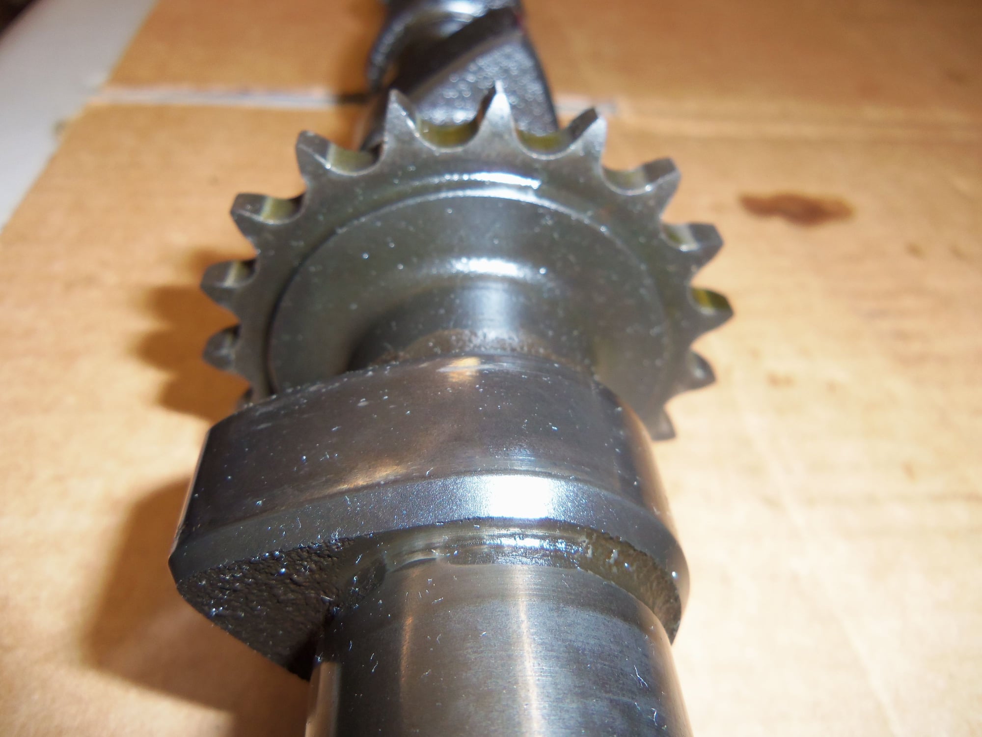
With the front bridge removed, I now understand how the axial thrust is dealt with on these camshafts. You can see the flanges on either side of the first cam bearing journal. These match up with machined surfaces on the ends of the bearing in the cap and head.
Note flanges on forward ends of both camshafts.
Machined surfaces on front and rear sides of bearings in front cam bearing bridge.
Flush with my success, I threaded the 6mm bolt into a hole in the casting of the back of the rear cam bearing bridge. I had enough clearance to swing the small brass hammer. After a few taps, the rear bridge came loose.
The actual releasing of the tension on the cam shafts was pretty anticlimactic. Less than a turn on each cam tool bridge stud nuts, and both cams were up and free.
Removal of the bridges was the same as installation. 8/4 came off just fine, 6/2 were a pain.
Releasing the tension on the camshafts with the cam tool bridges.
I had to get a little creative to remove both cam shafts at once. I grabbed the exhaust camshaft with both hands, lifted it up and over the intake camshaft, then hooked the intake cam with a pair of fingers. I was able to carry both cams like this to the work bench.
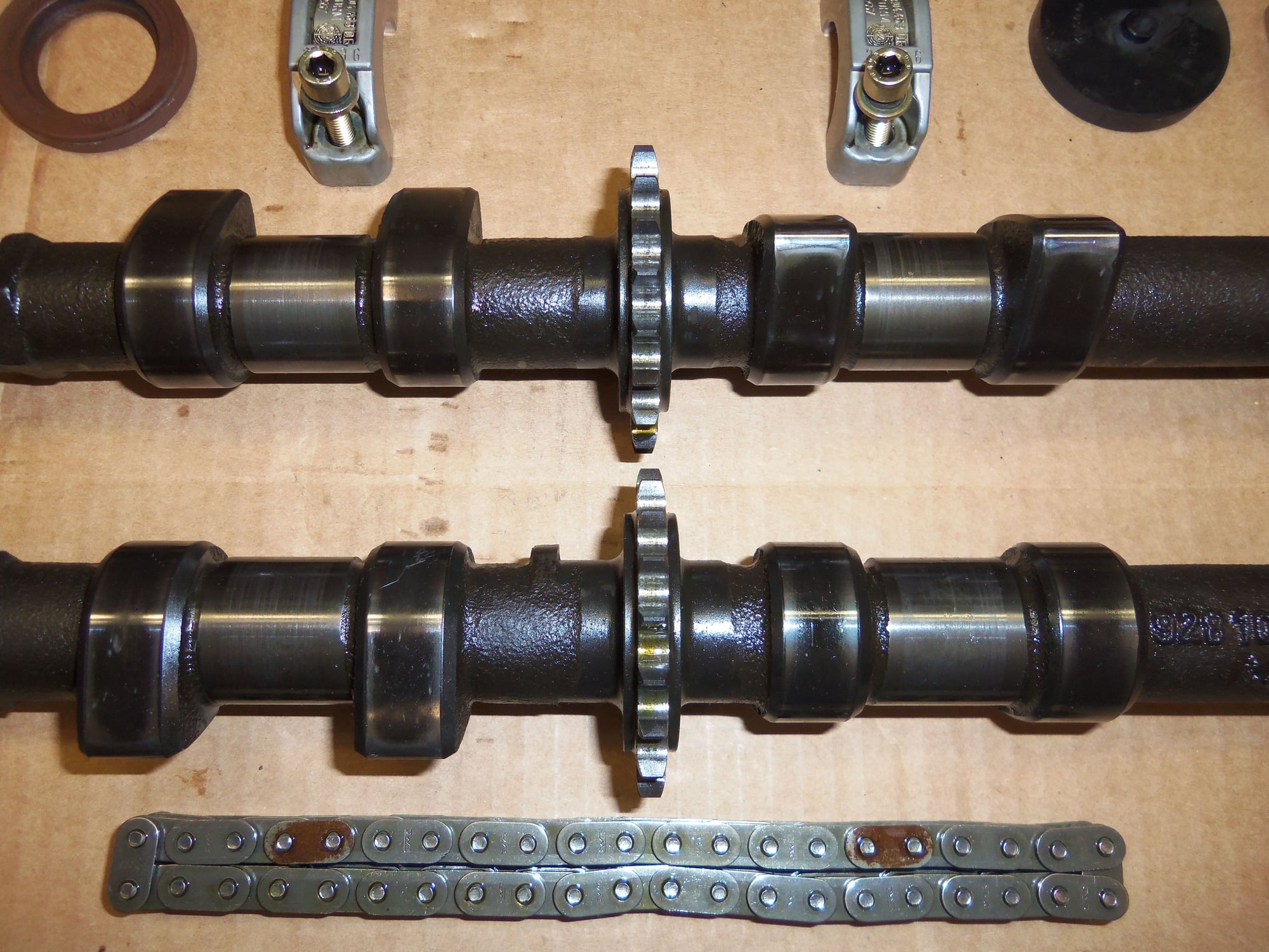
Once out of the chain, I could inspect the cams.
EDIT: It just occurred to me that I probably could have removed one camshaft at a time by lifting the camshaft up, then disengaging it from the chain. I will try that on reassembly.
I am pleased to say that I saw no horrible damage to the lobes. All the bearing journals look good. All the teeth on the sprockets look good, at least to me.
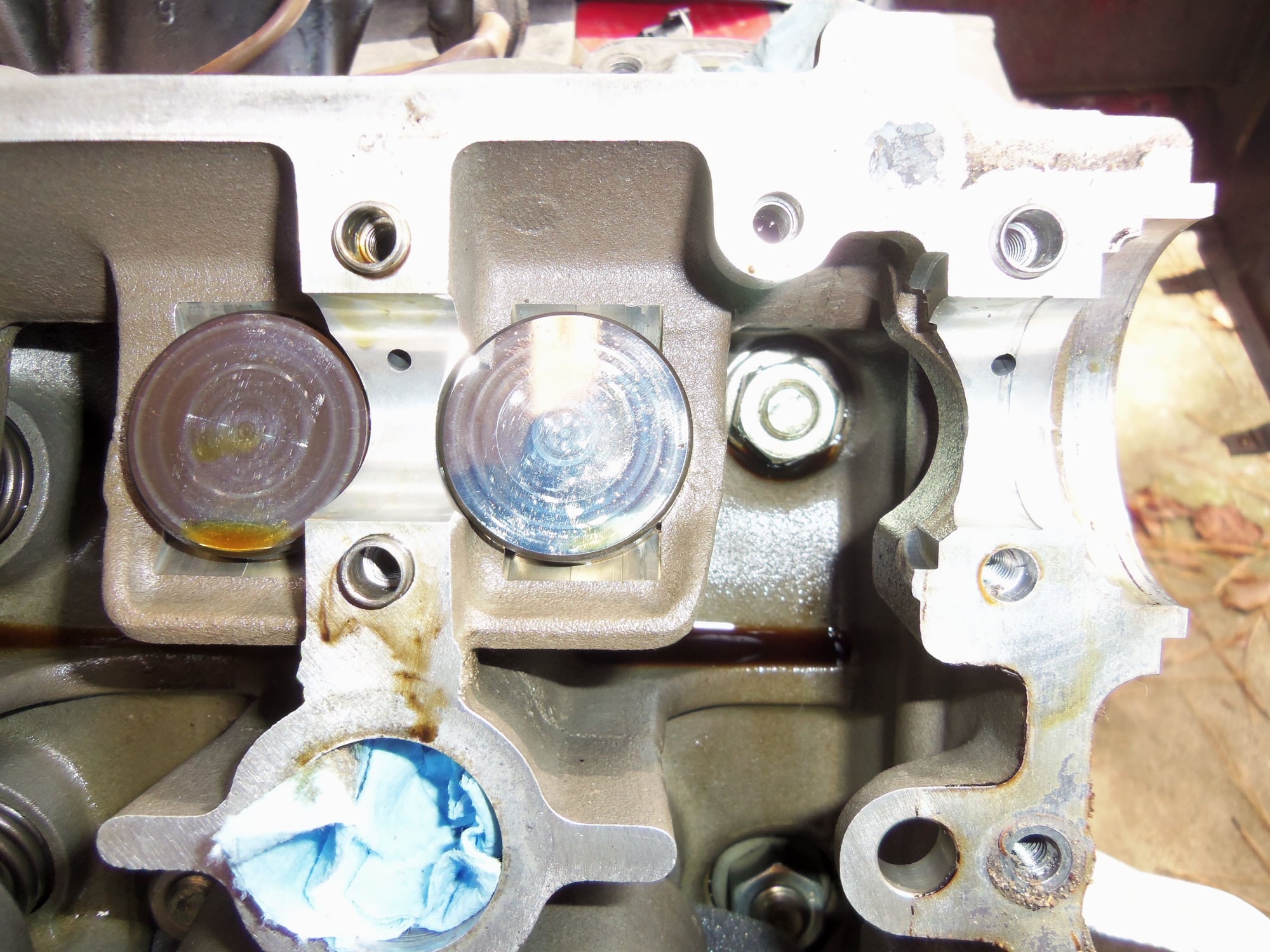
All 12 cam bearing surfaces in the cylinder head looked good like these two for the intake cam.
Bearing journals look good.
All 12 cam bearing cap and bridge surfaces look good.
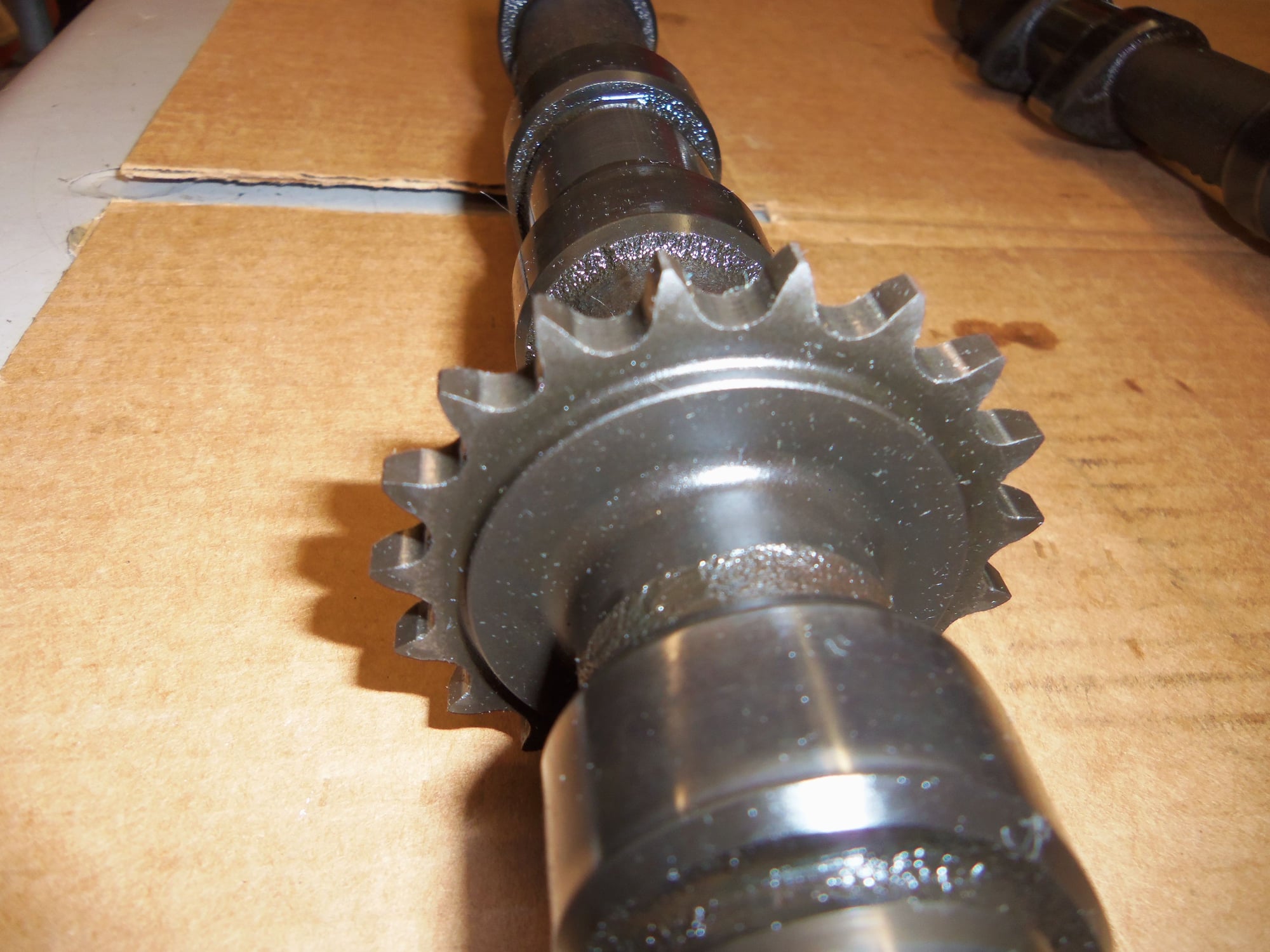
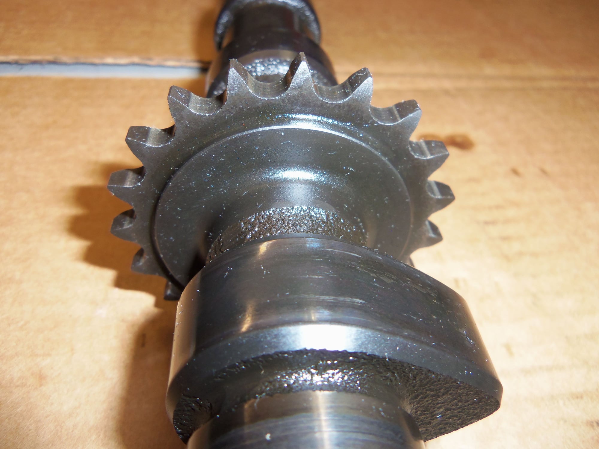
Half of teeth on exhaust cam sprocket.
Other half of teeth on exhaust cam sprocket.
Half of teeth on intake cam sprocket.
Other half of teeth on intake cam sprocket.
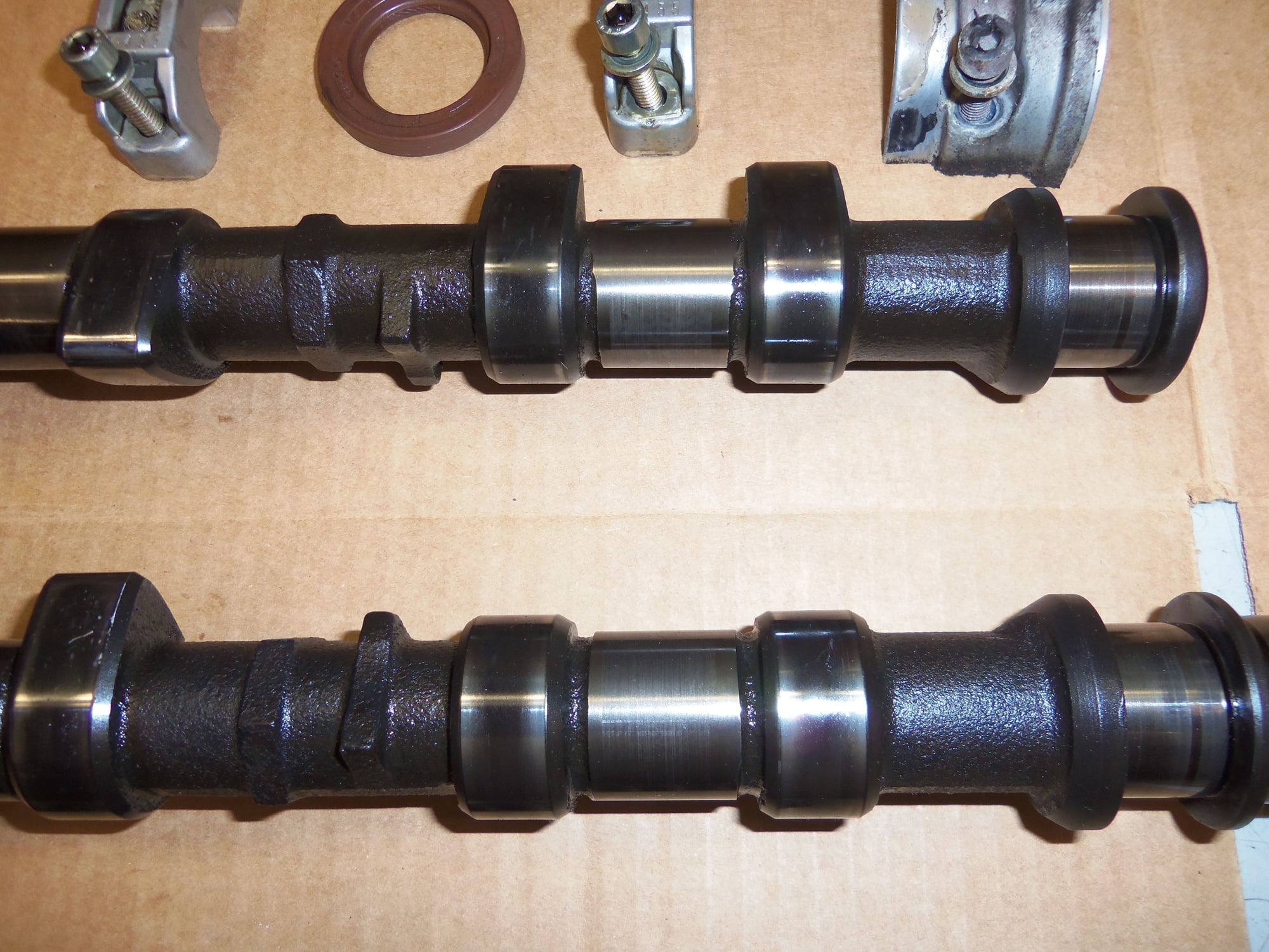
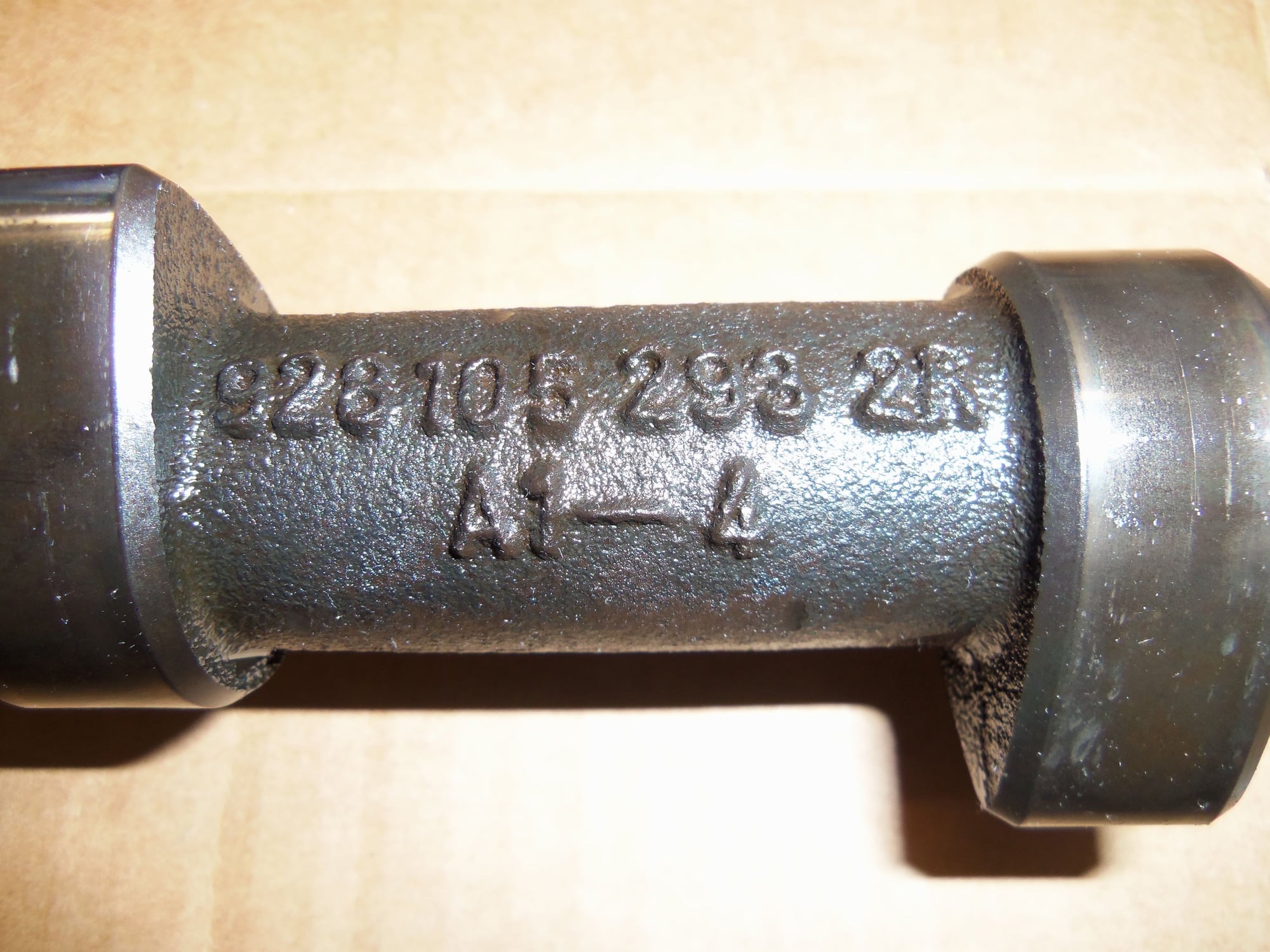
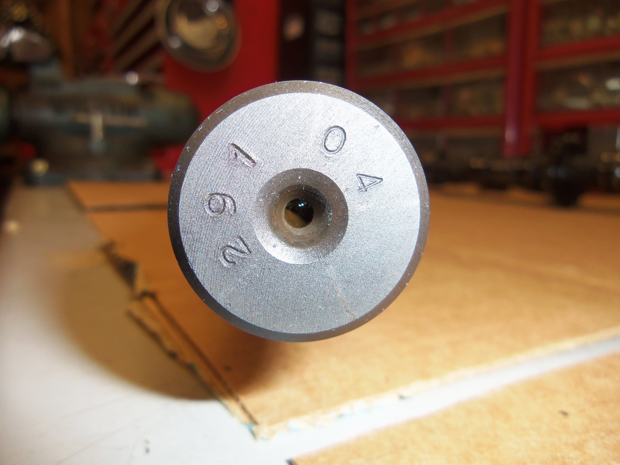
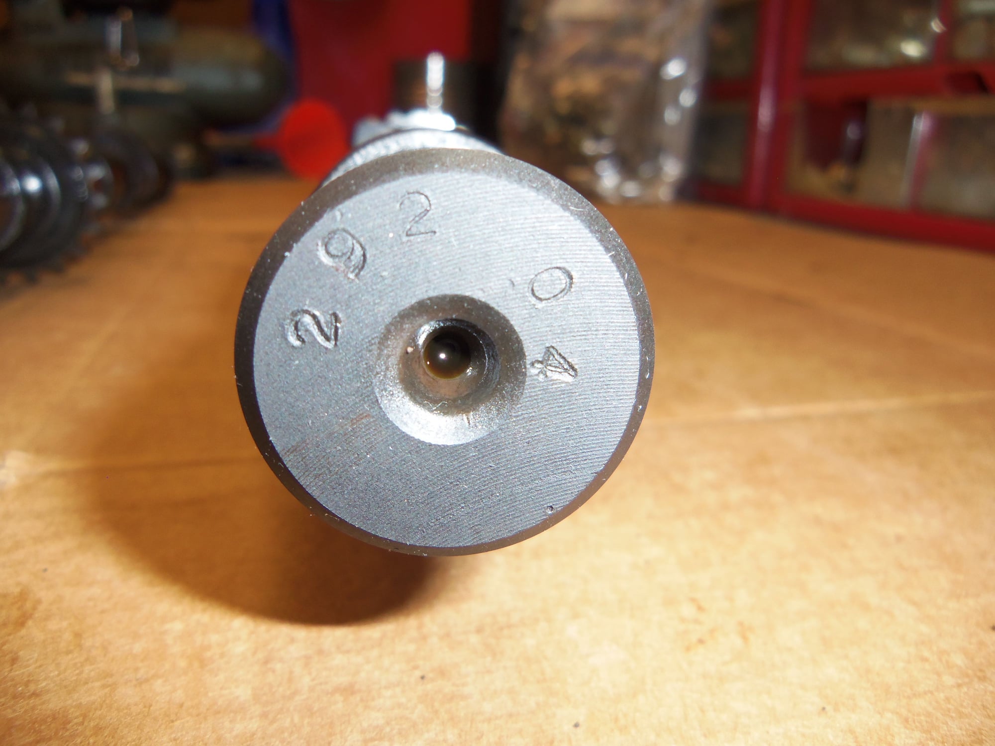
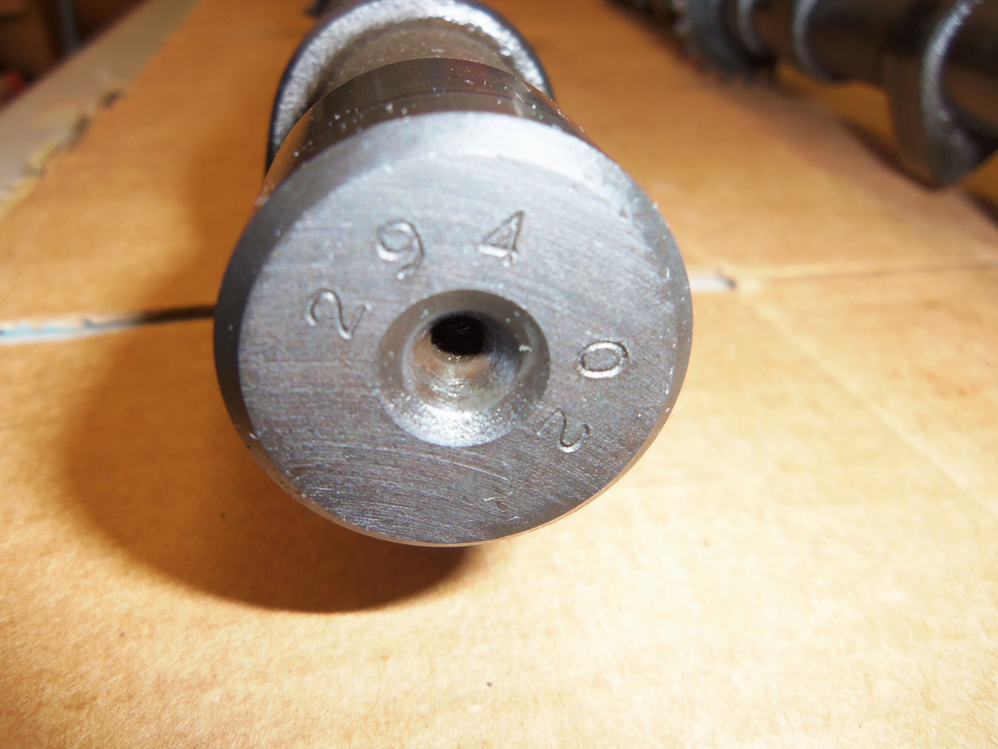
For the sake of posterity, I verified the numbers on my camshafts to the listed numbers in Section 15 of the WSM, page 15-124. They all match. I would hope so, as to my, and the PO's, knowledge nobody has been in here before.
Exhaust camshaft casting number.
Exhaust camshaft ID code number.
Intake camshaft casting number.
Intake camshaft ID code number.
The driver's side cylinder head camshafts went pretty much the exact same way.
Profile gauge fits very well.
All 12 cam bearing surfaces looked good, like these.
All 12 cam cap and bridge bearing surfaces look good.
Bearing journals look good.
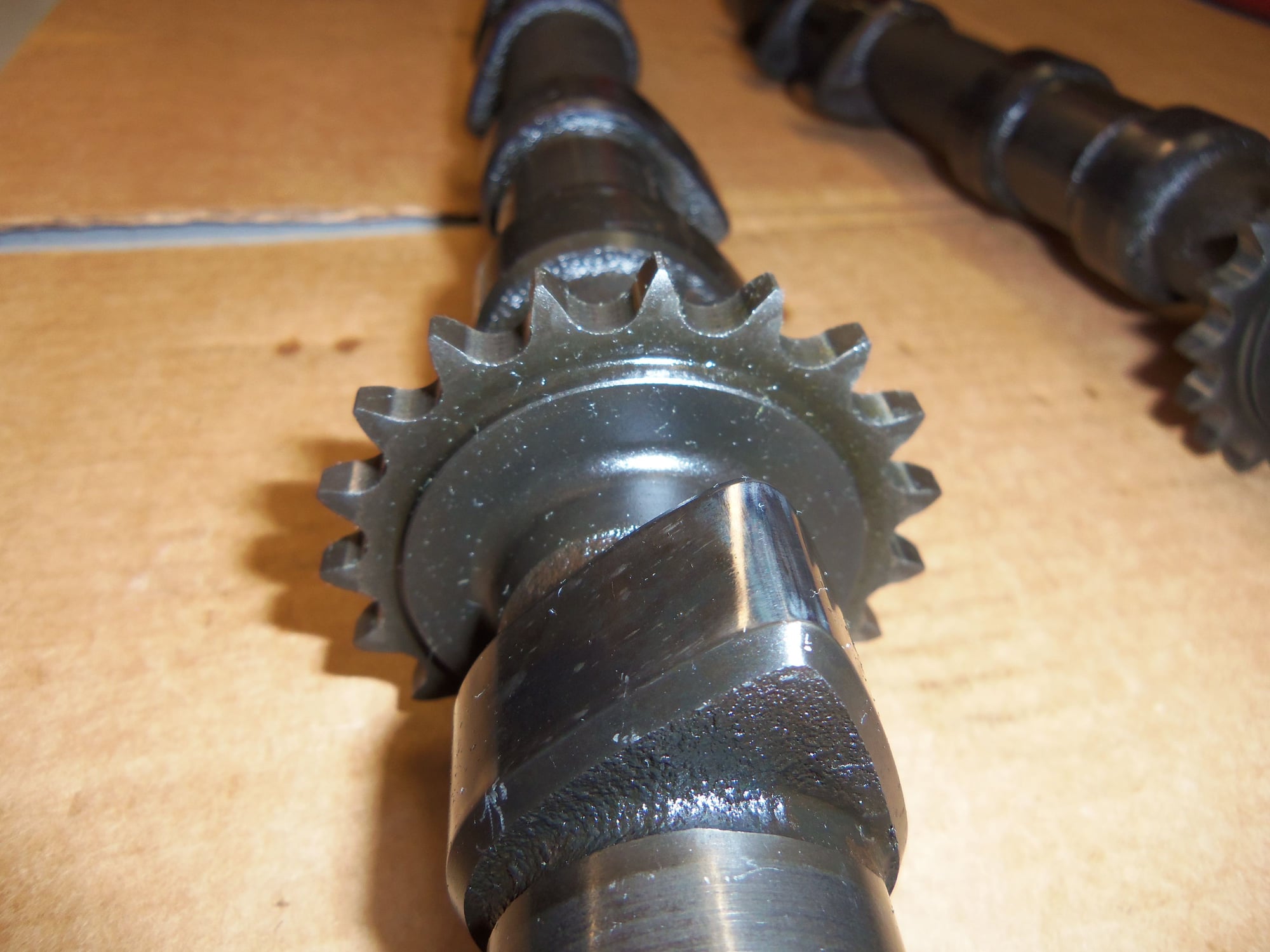
Half of teeth on intake camshaft sprocket.
Other half of teeth on intake camshaft sprocket.
Half of teeth on exhaust camshaft sprocket.
Other half of teeth on exhaust camshaft sprocket.
Intake camshaft casting number.
Intake camshaft ID code number.
Exhaust camshaft casting number.
Exhaust camshaft ID code number.
I did notice an issue and a couple of anomalies:
I think both exhaust lifters for cylinder #4 need to be disassembled and cleaned. All the other lifters feel springy when depressed with my thumb. These two feel very little spring, almost stiff.
Offending lifters for exhaust valves for cylinder #4. (Ignore the '4' stamped into the sealing rail. These lifters are for cylinder #4, not cam bearing cap #4.
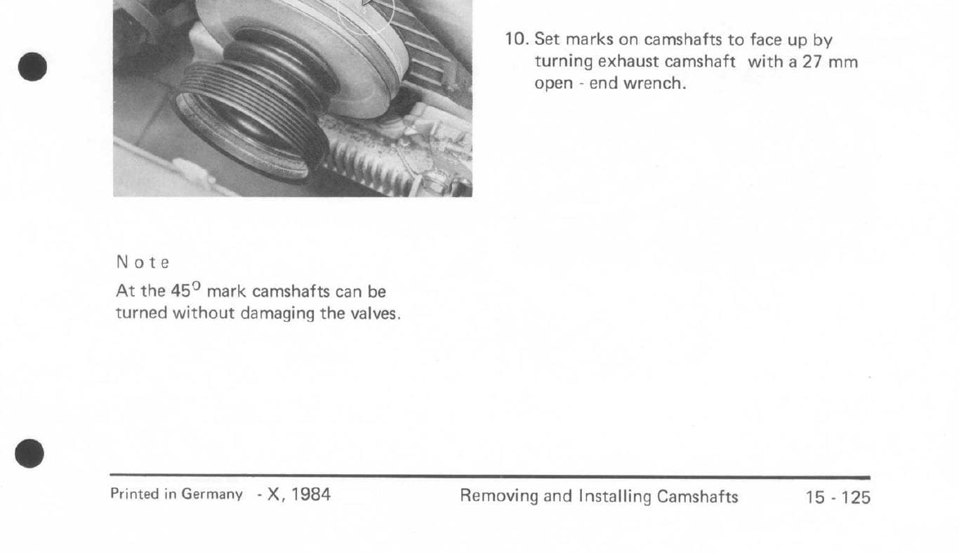
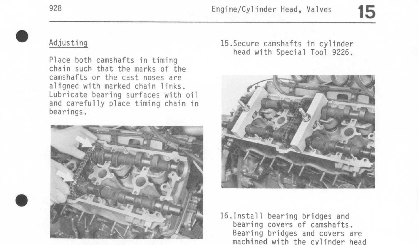
None of sprockets have an alignment mark on them. All the camshafts do have the alignment nub, though. Section 15 in the WSM, pages 15-125 and -126 describe aligning these marks to remove the camshafts. However, page 127 talks about using either the marks or nubs. Since my camshafts have the nubs, I'm good.
Page 15-125, note step 10.
Page 15-126, note arrows pointing to marks in lefthand photo.
Page 15-127, under 'Adjusting', note reference to marks or nubs.
Finally, even though all the 6mm screws that hold down the cam bearing caps and bridges are the same number, the threaded parts look different. And, its in a specific pattern. ALL of the screws that are on the outboard sides of the cam bearing caps, IE closest to the ID numbers, still have the gold cadmium plating on the threads. ALL of the screws that are on the inboard sides of the cam bearings caps have what looks like black oxide coated threads. I don't know if the gold cadmium plating has deteriorated in a specific way...?
As for the bearing bridges, the screws for them didn't really have a pattern. Some had gold threads, some had black.
I call this an anomaly, but not an issue. Just a curiosity.
Gold threads were outboard, black threads were inboard on ALL 16 cam bearing caps.
So...with that, I am now done with disassembly. Other than the two questionable lifters. I am now awaiting parts and will start cleaning parts.
With all of the work that you have put in so far, have you thought about going a little further, removing the heads, and replacing the head gaskets? I just went through this with my 87. When we removed the heads, there was degradation of the head gaskets allowing coolant to collect and begin corroding the aluminum. It was easily corrected but had I waited a few more years, I may have had to got the route of welding and resurfacing.
With all of the work that you have put in so far, have you thought about going a little further, removing the heads, and replacing the head gaskets? I just went through this with my 87. When we removed the heads, there was degradation of the head gaskets allowing coolant to collect and begin corroding the aluminum. It was easily corrected but had I waited a few more years, I may have had to got the route of welding and resurfacing.
Originally Posted by Imo000
I agree, might as well pull engine and the heads.
Gentlemen, I appreciate the suggestion, and understand the logic. Head gaskets are a weak point on 928 engines. As is the inevitable corrosion of the head deck surface.
However, I am going to pass at this point. Pulling the engine to do the heads is opening an expensive Pandora's box that I don't want to deal with now.
Yes, I am likely shooting myself in the foot for later.
Pulling the engine will mean:
-head gaskets
-clean, weld, machine heads
-valve guides, valve job
-completely disassemble heads to clean oil passages
-dealing with possibly corroded head studs, might have to replace ALL of them
-cleaning the deck surface of the cylinder blocks
-REAR MAIN SEAL!!! Big scare here. I am reading that installing a rear main seal on a 928 has become a 50/50 crap shoot on whether it leaks. I don't have an engine test stand, and don't want to find out it leaks until AFTER I install the engine. I don't know what to do about the rear main seal at this time.
-purchasing a suitable engine stand
-TIME. I am already chomping at the bit to get the Red Witch back together and drive. It has been 15 months and still going. All of the above needs to be done in a timely, yet UNHURRIED manner. Which means a later time.
I am still in a hole to the tune of a few thousand dollars for what I am doing now. I would prefer to pay that off, then save up for the above work. Then do that work at a more appropriate time.
The Elring RMS so far has proven to be the best one, same goes for their wheel bearing seals as they are copies of the original, better designed seal.
Also, if you ever replace the studs, you need to replace all of them. Porsche moved to a different alloy that will not yield like the originals and needs to be torqued to IIRC 66ft/lbs.
Angle torquing the new studs as per WSM torques them in excess of 100 ft/lbs. But his is a topic for another thread.
Either way, best of luck on your extensive top end refresh.
No worries. there is certainly a significant amount of time and effort, not to mention expense, if you were to walk down this path. One thing to note. It is possible to pull the heads without removing the engine. Not the most convenient and perhaps not the smartest way to go about the job. But, it is possible.

 10-10-2017, 03:48 AM