When you click on links to various merchants on this site and make a purchase, this can result in this site earning a commission. Affiliate programs and affiliations include, but are not limited to, the eBay Partner Network.
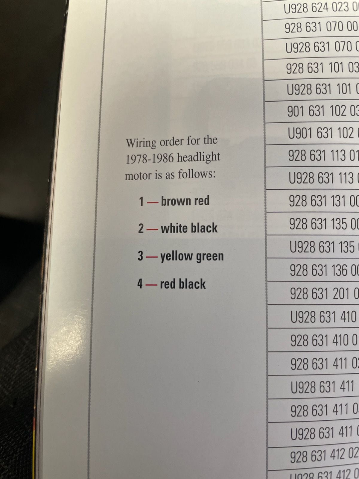
When I bought my S2 the headlight motor was disconnected as the original had failed. OK so I thought it would be easy to connect based on colours/pin numbers.... but seems not. The motor connector has pin numbers 1 to 4 identified - no wire colours visible. The loom wires are white/black (ws/sw), yellow/green (gn/ge), red/black (rt/sw), brown/red (br/rt) and match the diagram I have, but the diagram is ambiguous as there is no mention of 1-4. Anyone know how the 1-4 pin numbers map to the colours?
Alternatively does anyone know if there is any risk if they are connected in reverse to find the right order??
Thanks for the replies everyone - Yup agree the wiring order is probably correct on the diagram. So check pin continuity in 2 directions to identify the earth right?
Amazed the diagram doesn't have numbering I have to say
Thanks for the replies everyone - Yup agree the wiring order is probably correct on the diagram. So check pin continuity in 2 directions to identify the earth right?
Amazed the diagram doesn't have numbering I have to say
D
You are identifying where the red/black (power) wire goes. Ground (=Earth) for the motor is the case (there is no wired connection for this). Just do exactly what I suggested - use a DVM in ohms or (better) continuity tester mode for this.
So pin 4 checks continuity with the case. Connected using Optio B but when reftting, the central shaft sparked against the motor bracket on the car - live! Reversed connections same result. Going to have a really long hard look at the wiring diagram and possible failure modes when i get back to the house!
D
The pods are not designed to be in intermediate positions - if they are the motor will run until it gets to an "up park" position or a "down park" position (this is built into the motor).
With the motor off the drive shaft and the case grounded - connect as appropriate - the motor will run until it gets to the park position. With headlight switch off it will run to the "down park" position.
Now install the motor and connect the pod drive shaft with the pods in the down position.
Thanks for the reply, I understand that there is not intermediate position so either lights down or up - fine. The thing I think is wrong is that the drive shaft that the crank connects to has 12v on it....something is not right in the "new" motor.
Have a spare from my "parts car" that I will try next, and go again with Option B. Keep you posted
It will be exactly the same - try it - this is quite normal assuming you haven't installed the motor yet.
Again - there is no ground connection until the motor is installed since the case is the ground.
Practically this means until you install it the whole case will be at 12v IF the red/black wire is powered @12v (and we know it is from what you said before).
I know this is not very intuitive - but that is how electricity works...
Mmm interesting. I looked at the wiring on my "spares" car and it looks different to the wiring diagram but in line with Ladybug83s thoughts. Will try alternatives and report back!
Can anyone help with these wires on my 1980 928?
If Option A in the thread above:
the Position 1 wire looks like Red/Black which is correct
the Position 2 wire looks Green which should be in position 3?
the Position 3 wire looks White/Black which should be in position 4?
the Position 4 wire looks Brown/Red which should be in position 2?
Option A:
1 - Red/Black
2 - Brown/Red
3 - Green/Yellow
4 - White/Black
I've done both Option A and Option B and no response from the head light motor. Nor do the head lights turn on.
Any advice/corrections on the Color wiring to Positions 1-4 much appreciated.
Anyone know how to test if the itself motor works?
Last edited by 928Collector; 01-27-2024 at 04:09 PM.
1980 928
Thanks. Head lights will not raise/lower or turn on.
yes. i've connected/disconnected the wires/connections. I did it for Option A & Option B.
I've checked the fuses.
I've replaced the relay.
I've removed the motor can cleaned/buffed/Deoxit the silver rotary disk as well as the copper/magnet circular parts.
the light switch works - parking/fog lights come on and all my interior lights work - i've gone thru them one by one including the glove box and rear hatch lights.
its like power is some how not getting to the actual motor.
in another instance I put a 9volt battery to the spade and it powered a fan.
I realize that may not be the case with the head light motor but I'm looking for advice on what power source i can put on which wire to just prove that the headlight motor operates.
Last edited by 928Collector; 01-27-2024 at 07:35 PM.

 09-22-2017, 05:11 PM