When you click on links to various merchants on this site and make a purchase, this can result in this site earning a commission. Affiliate programs and affiliations include, but are not limited to, the eBay Partner Network.
Arnoud, I am late to this thread. I want to toss out an outlandish idea. I see your GTS is an automatic. Have you checked the flexplate preload recently? I ask because I chased a similar belt tracking issue on my Red Witch. After releasing the built up flexplate preload, the TB tracked properly. I can't fully explain it, but it was a thing.
Just wanted to bring it up.
Good Luck! and I hope you make your April goal!
If you slip the tensioner arm back on the post and mount the retaining bracket with the counter sunk small allen bolt nipped tight, how much axial float [if any] is present? We are assuming there is little float there but perhaps you can confirm that just to be clear.
I think you will have to measure from the mounting surface of the pivot bolt on each waterpump and use one of the attachment bolt holes to measure from.
Thanks for the detailed measurement advice, Stan. I will do so, once I have found my previous removed Porsche WP and a spare brand new Laso WP that I still have "in stock" - and report back here.
Originally Posted by skpyle
Arnoud, I am late to this thread. I want to toss out an outlandish idea. I see your GTS is an automatic. Have you checked the flexplate preload recently? I ask because I chased a similar belt tracking issue on my Red Witch. After releasing the built up flexplate preload, the TB tracked properly. I can't fully explain it, but it was a thing.
Just wanted to bring it up.
Good Luck! and I hope you make your April goal!
Thanks Seth, and about anything - never mind how remote (as I have to admit that the possible logic behind this, I can not follow at the moment) - that I can eliminate from the list is good. I had not checked the flexplate preload since my last TB & WP change during April 2014, so I had a look this evening. Do note that I have a - very beefy - clamp on it (as sold by Theo Jenniskens), as one of the very first things I modified in May 2011. I tested it with a straight-edge thick piece of aluminium (that I still had stored in the car for these kind of tests), and all seems still perfect to me:
Originally Posted by FredR
Arnoud,
If you slip the tensioner arm back on the post and mount the retaining bracket with the counter sunk small allen bolt nipped tight, how much axial float [if any] is present? We are assuming there is little float there but perhaps you can confirm that just to be clear.
Good point on measuring the axial float play for the idle roller. I also checked that this evening with taking two measurements:
So: 20,28 - 19,77 = 0,51mm and 19,55 - 18,94 = 0,61mm of axial float measured. Once I have found my old Porsche WP + spare new Laso WP, I will measure it on those as well - and report here. Could this axial float explain the tracking "problem" on the tensioning roller of about 2mm?
I could not read much into your photos so not sure what you actually measured but the intent of my query was if you mount the tensioner pulley assembly how much float would there be if working the assembly backwards and forwards by holding the tensioner pulley. I would think there should be little float on the tensioner pulley with a little float on the pivot pulley. If the 0.6mm measured represents such I would not think that is excessive given we are trying to explain 2mm. but I have never seen a spec actually that defines such albeit somewhere i would expect such to exist.
What perhaps you should also be measuring for each of the pumps you have is the dimension from the pump mating face to the base of the pivot post and from the base of the pivot post to the inboard side of the securing bracket. This might lead to clarity as to why the tensioner pulley is riding 2mm inboard of where it ideally should be.
Fred,
Those previous photo's showed me measuring twice the pivot pulley float, that being the maximum of: 0,61mm. This evening I first measured twice the tensioner pulley float:
I only noticed afterwards that I had it set on measuring in inches instead of mm, so the calculations are:
- First measurement: 2,1085" - 2,0445" = 0,064" = 1,6mm
- Second measurement: 2,1115" - 2,055" = 0,0565" = 1,4mm
So a maximum of 1,6mm tensioner pulley float, cause by the idle pulley float of 0,61mm. I guess this explains it all, where that about 2mm comes from....
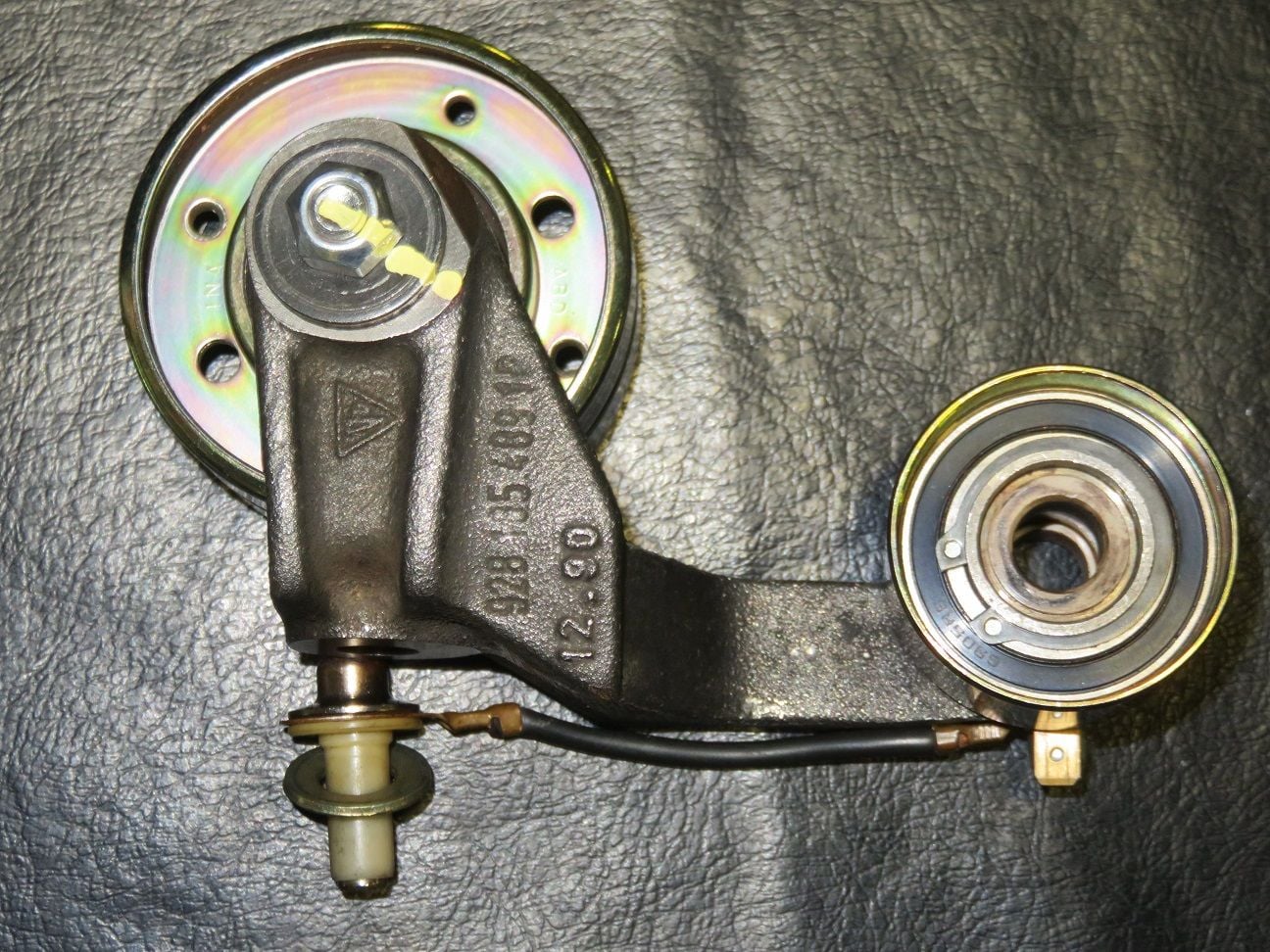
Furthermore I followed your other suggestion, of measuring my old previous Porsche WP, and another still new Laso WP:
That is 37,97mm for the pivot bolt shaft length, of my old Porsche WP.
And 28,82mm from the back till to the start of the pivot bolt shaft, of my old Porsche WP.
The above is a look of the back of my old Porsche WP. The barring is still fully fine, and it has a plastic impeller (not shown here).
That is 38,08mm for the pivot bolt shaft length, of my new Laso WP.
And 29,02mm from the back till to the start of the pivot bolt shaft, of my new Laso WP.
The above is a look of the back of my new Laso WP, and it too has a plastic impeller (not shown here).
Question for the 928 brain trust: is it normal to have about 2mm play of the tensioner roller, which _might_ then result - as in my example - with the timing belt not completely running over it? I.e. put the tensioner arm back to the current in place WP, or not?
Asking this, because I'm still looking for the root cause of the timing belt skipping one tooth and wonder if this might have had anything to do with it - or is just another "red herring"...
Arnoud,
By my deductive reasoning [not perfect but not too shabby] a tensioner fault would not skip a tooth and then mysteriously "stabilise". The lower roller that sits under the crank sprocket and seems to do little does in fact help prevent the belt slipping in the event of a backfire or some trying to rotate the engine backwards [a big no no when the belt is strung].Whether or not your issue was caused when the belt was last strung remains to be seen but it is seemingly a common error!
That your pulley is floating by the amount it appears to be is something of a mystery to me. I had hoped to check mine for comparison but I failed to get round to it yesterday so that will have to wait until I return to base [just about to fly on a Boeing 737900 - Omanair have pulled their 737 Max 8's from service for the time being!].
That end float just does not seem right to me- hopefully someone more knowledgeable will guide you further.
Thanks Fred, for your continued follow up and guiding. My pulley float remains a mystery for me too, so let me further document here what I have done in the meantime and where I am now.
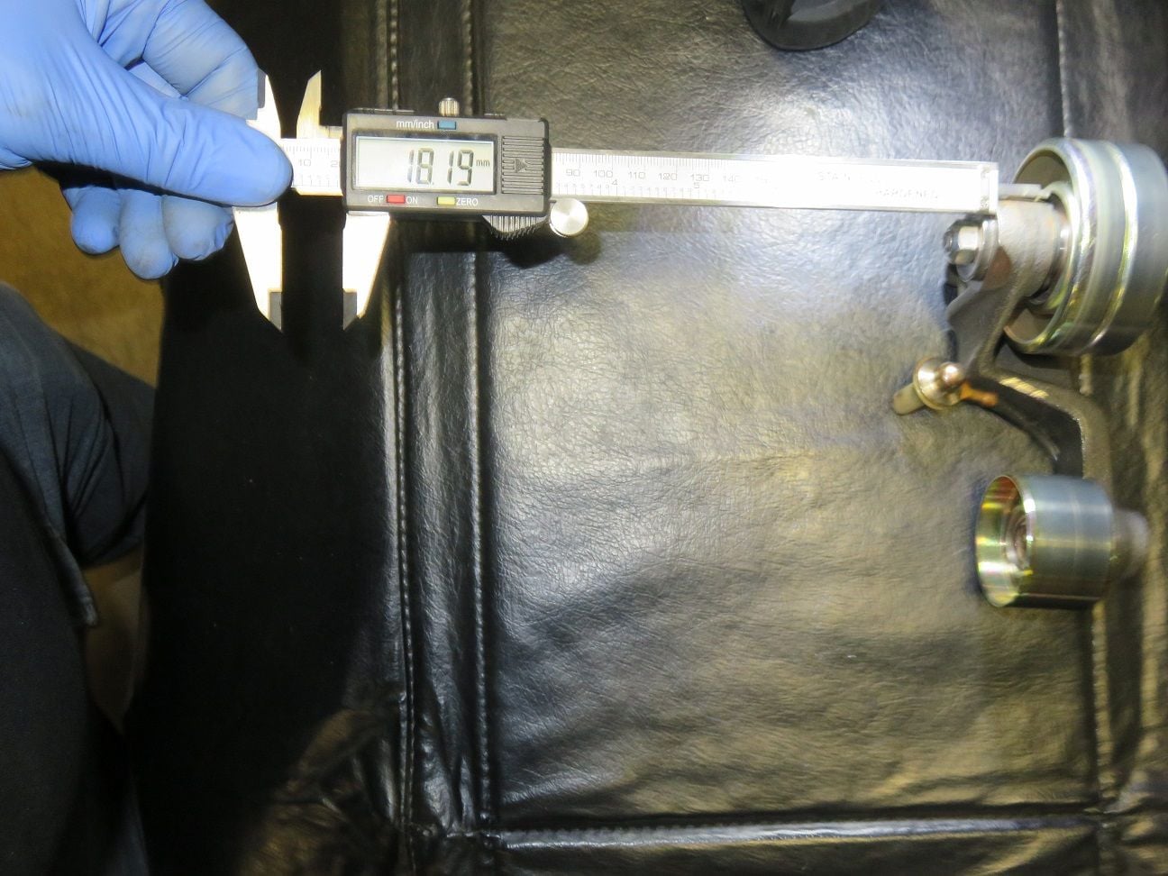
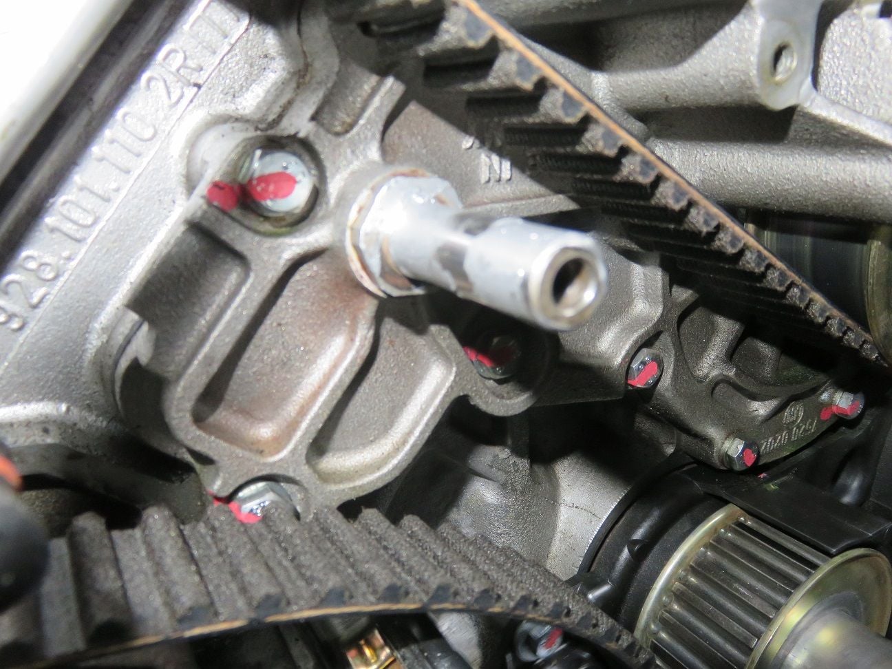
After further discussions locally in Helsinki with Erkka, we were wondering if something was wrongly made with the machining of my particular tensioner arm. Mine measured a little bit over 18 mm "thick":
Erkka checked one that he had, which also turned out to be 18 mm. So that was not the problem here...
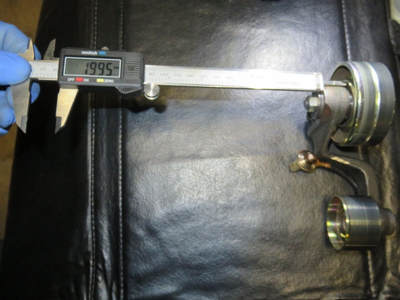
And yep: the cir-clip that I added already in April 2014, is about 1,75 mm "thick" (19,95 mm - 18,19 mm = 1,76 mm) , as it should be as per PET specification:
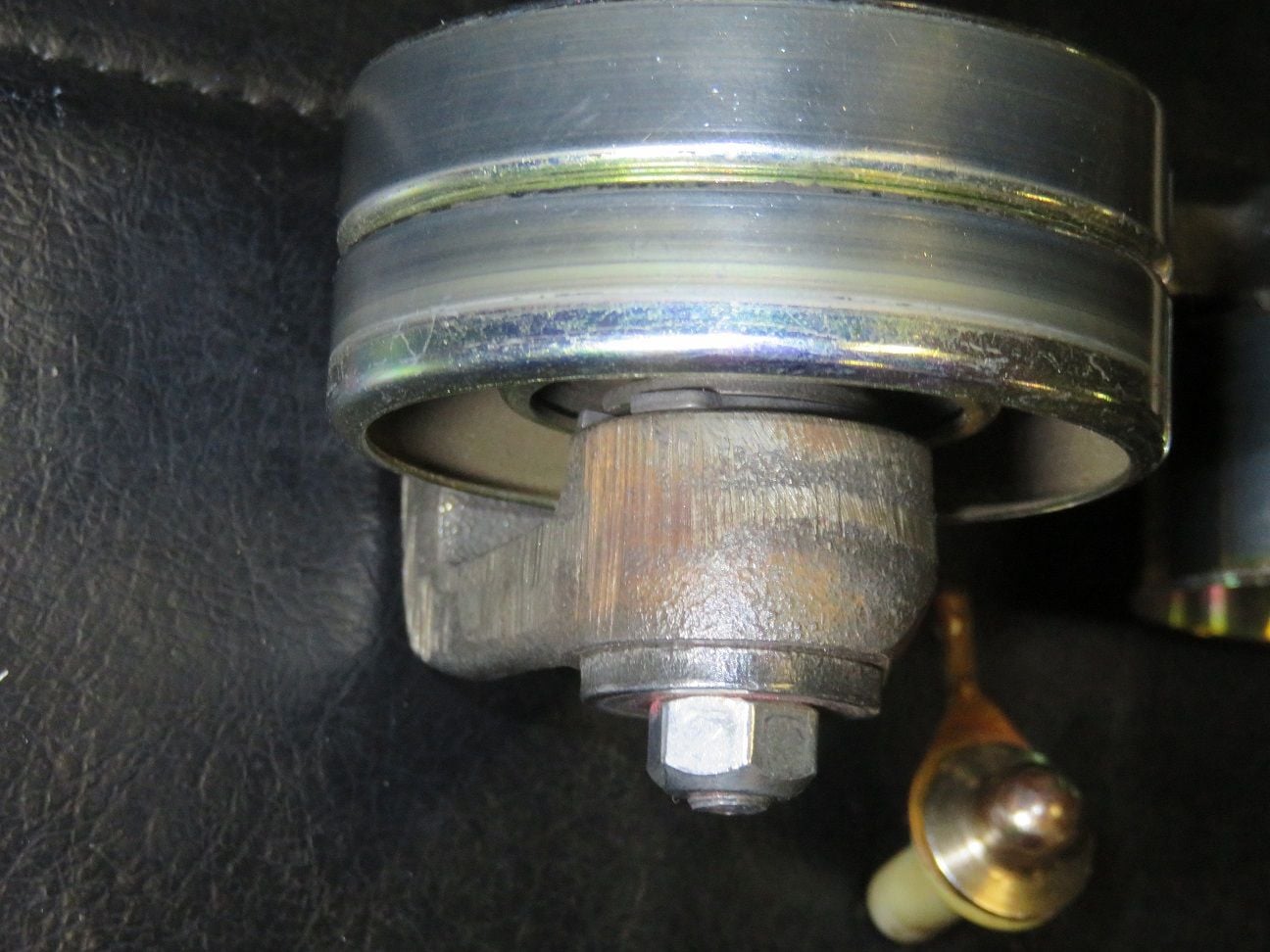
After further talks with Erkka, I decided to add another such cir-clip on top of the existing one, thereby pushing it out by 1,75 mm - which is close enough to my earlier measured 1,6 mm float. The second cir-clip is of course not seated in the groove, just on top of the other one, but that is totally fine because that part is not turning nor spinning at all (as the bearing is instead). You can see both cir-clips here:
Erkka correctly reminded me to then leave out the smaller washer when re-torquing the bolt, otherwise the nut would no longer be flush and then all becoming too long:
A little bit of aluminium paste put on the water pump pivot pin back and front:
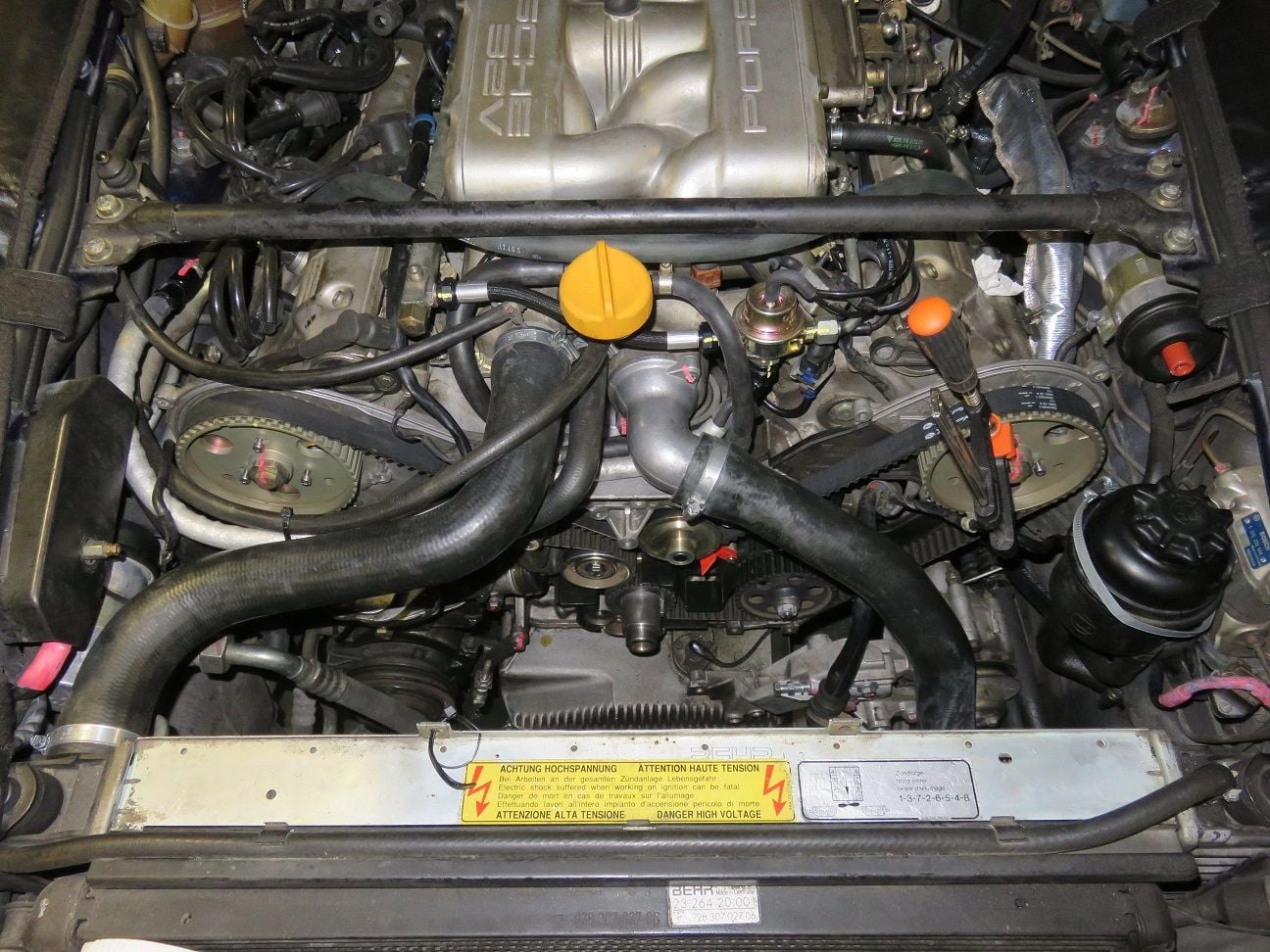
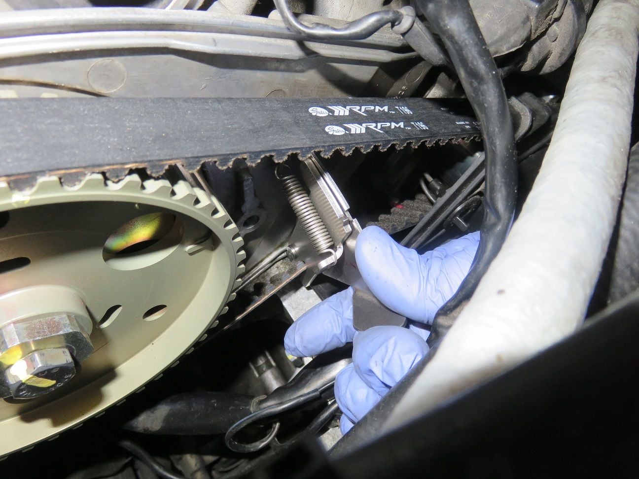
And all assembled back, with the Gates racing belt T196R put into place:
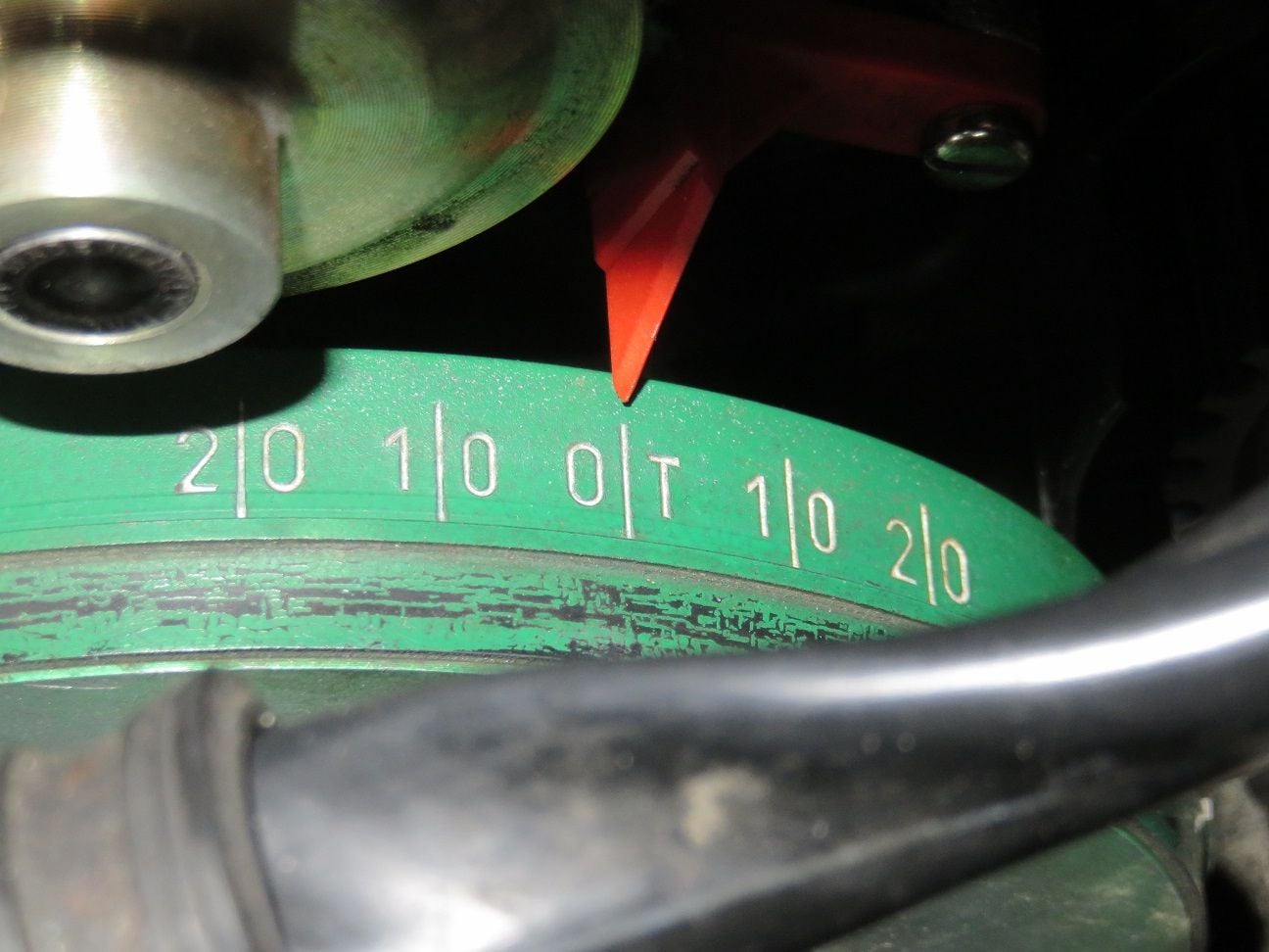
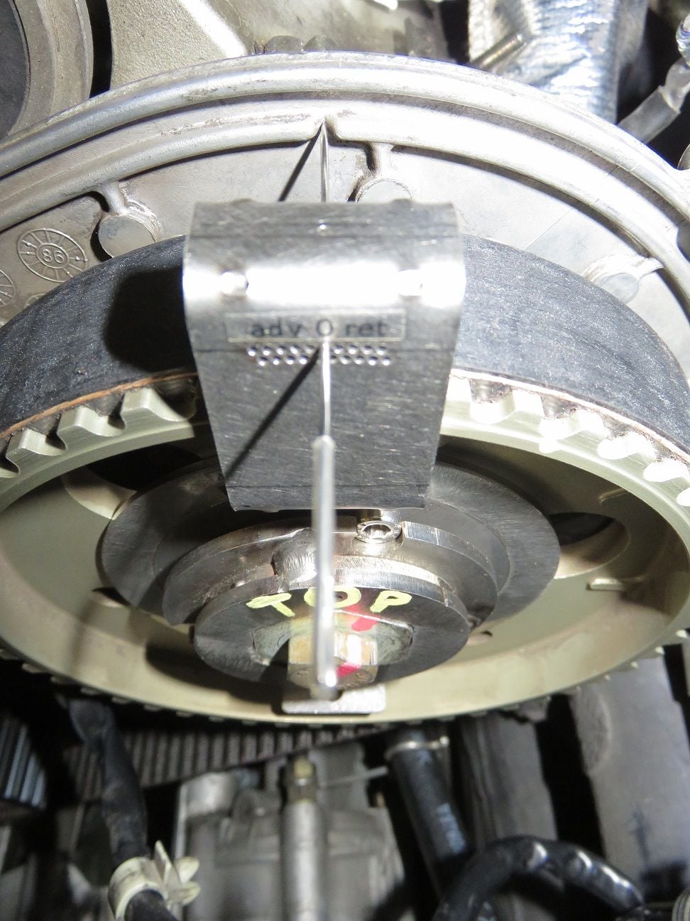
Timing put on zero degree TDC (after having removed the locking tool):
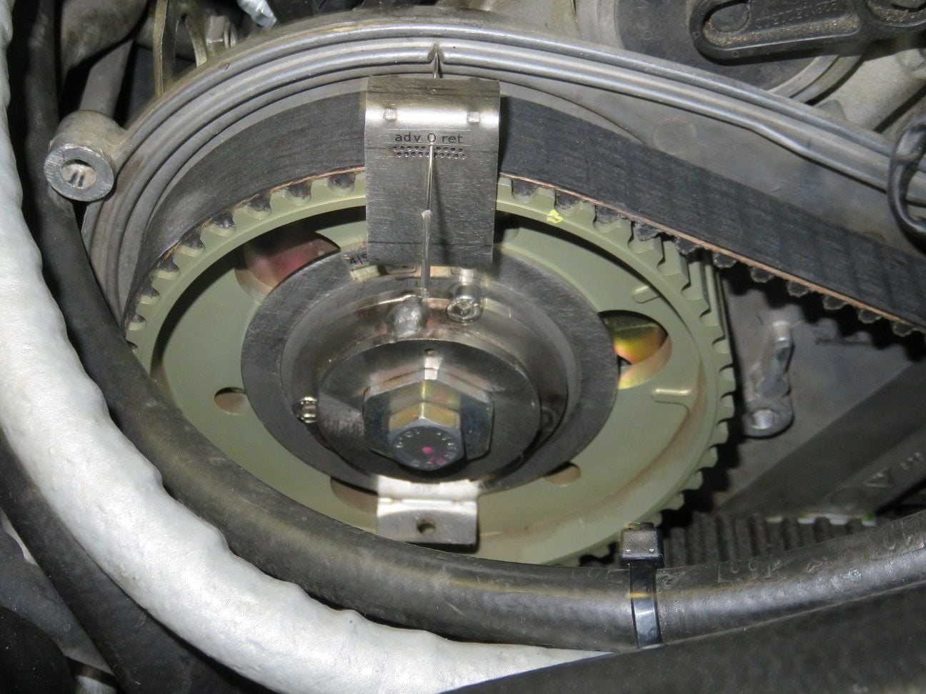
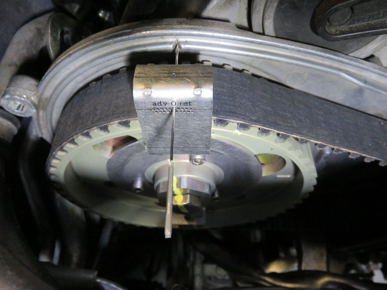
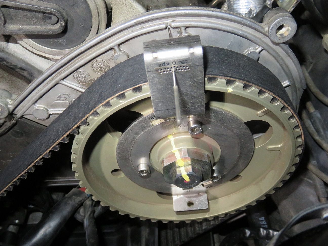
And then using the Porken (thanks so much for having developed that, Ken!) timing tools for setting the timing. I went with 0 degree for both banks this time, because it seems - and I hope that such is indeed the case, fingers crossed and all that! - that with PS 1-4 having become retarded as much as it had (-9 degrees) all my original problems and why I started this thread and now almost 2 years "quest" have happened. So I rather have 1 or 2 degree advance, than any retard...
PS 1-4 timing setting:
And then DS 5-8 timing setting:
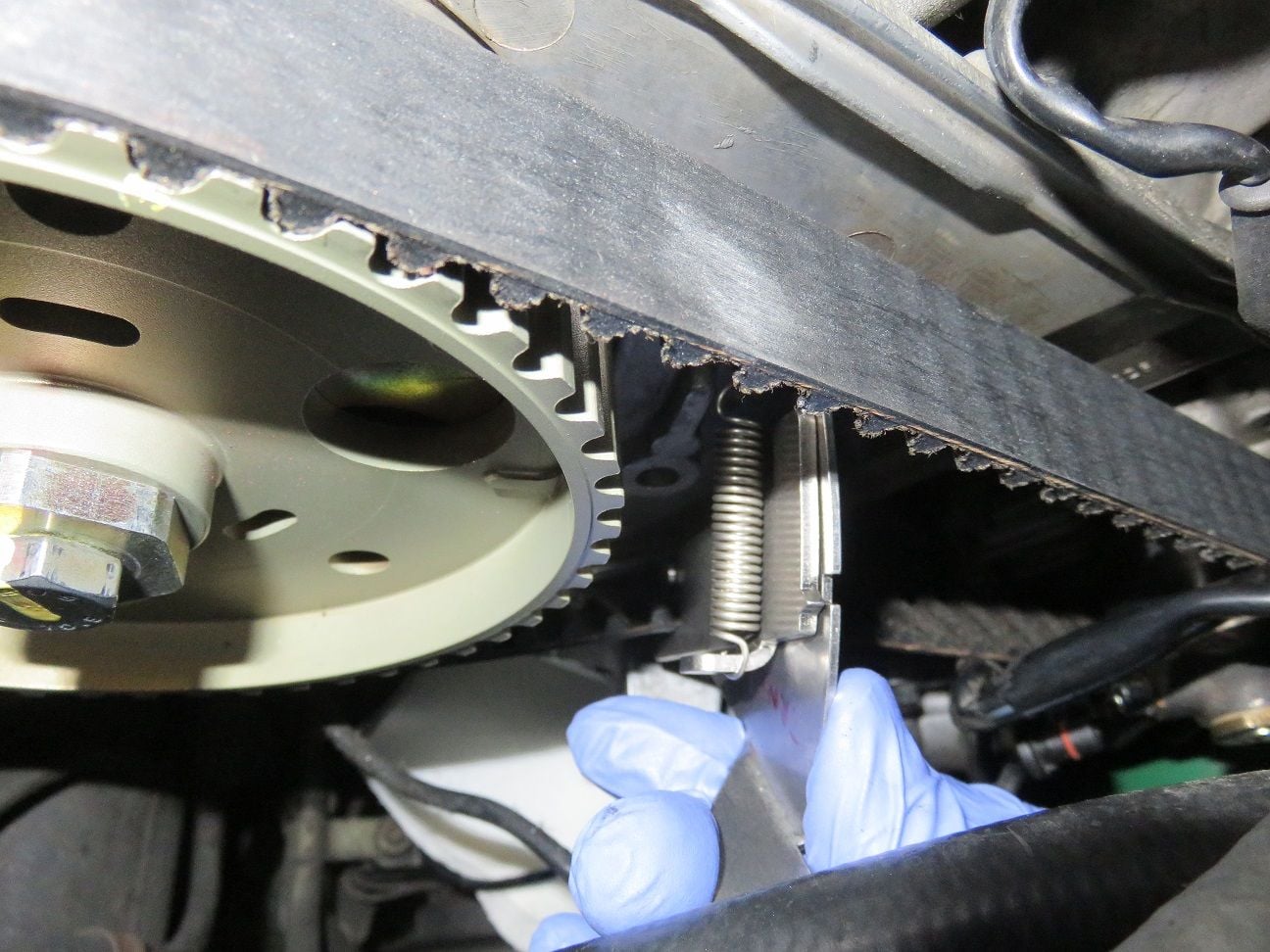
And yes: before and after I had first tensioned the timing belt and checked it. Here is me re-checking it afterwards once more:
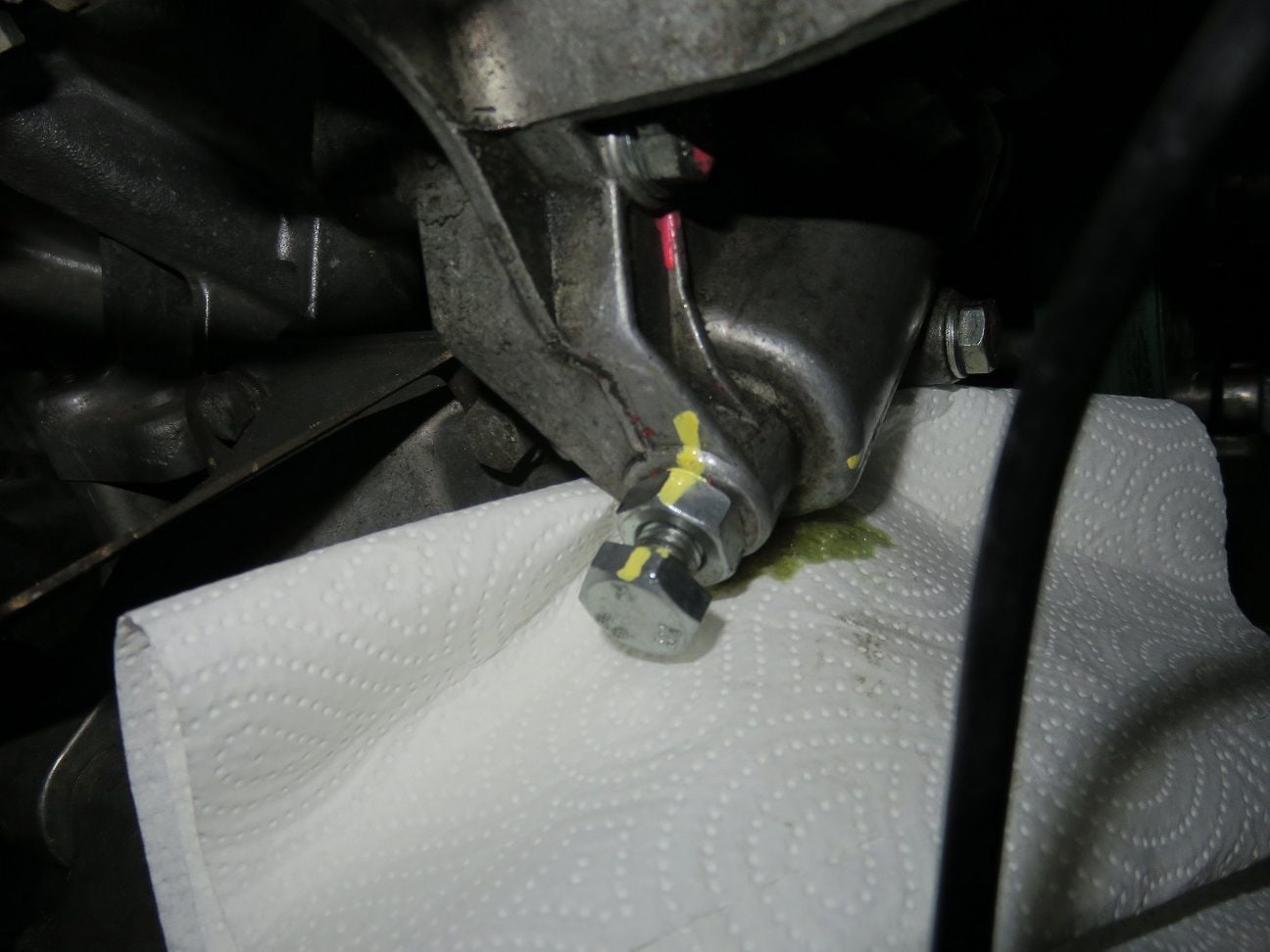
And final setting markings. The green stuff on the paper towel is weak thread locker, obviously I used a bit too much...
As I had a brand new hall sensor ordered some time ago, now -if ever - was a good time to replace it. Search is your friend as is often written here, and I have to thanks the following Rennlisters:
- Mrmerlin / Stan, for his excellent description on how to best tackle this rather tedious job, as there is hardly any space to get tools in. See this thread for his details, which I followed to the letter here and worked like a charm first time: https://rennlist.com/forums/showpost...8&postcount=18
- worf928 , for his description of how to deal with this new hall sensor that does indeed has a shorter pigtail than the original one: https://rennlist.com/forums/928-foru...l#post14629190
Oh: and it does help that in my car I have long ago removed the air pump and all it's pipe work (as I do not need it, and still passing all yearly smog test as compulsary here in Finland with flying colours) . Much more room for this job thereby.
So here I am following Stan's instructions on how to get to the upper allen bolt. I moved the lift hook out of the way by opening it's 13mm nut several turns, and then used a 4mm allen bit put into a very small 10 mm socket and then a short extension into a 1/4" wrench:
And then a 10 cm and a 20+ cm extension, so to get correct straight angle on the bottom 4 mm allen bolt:
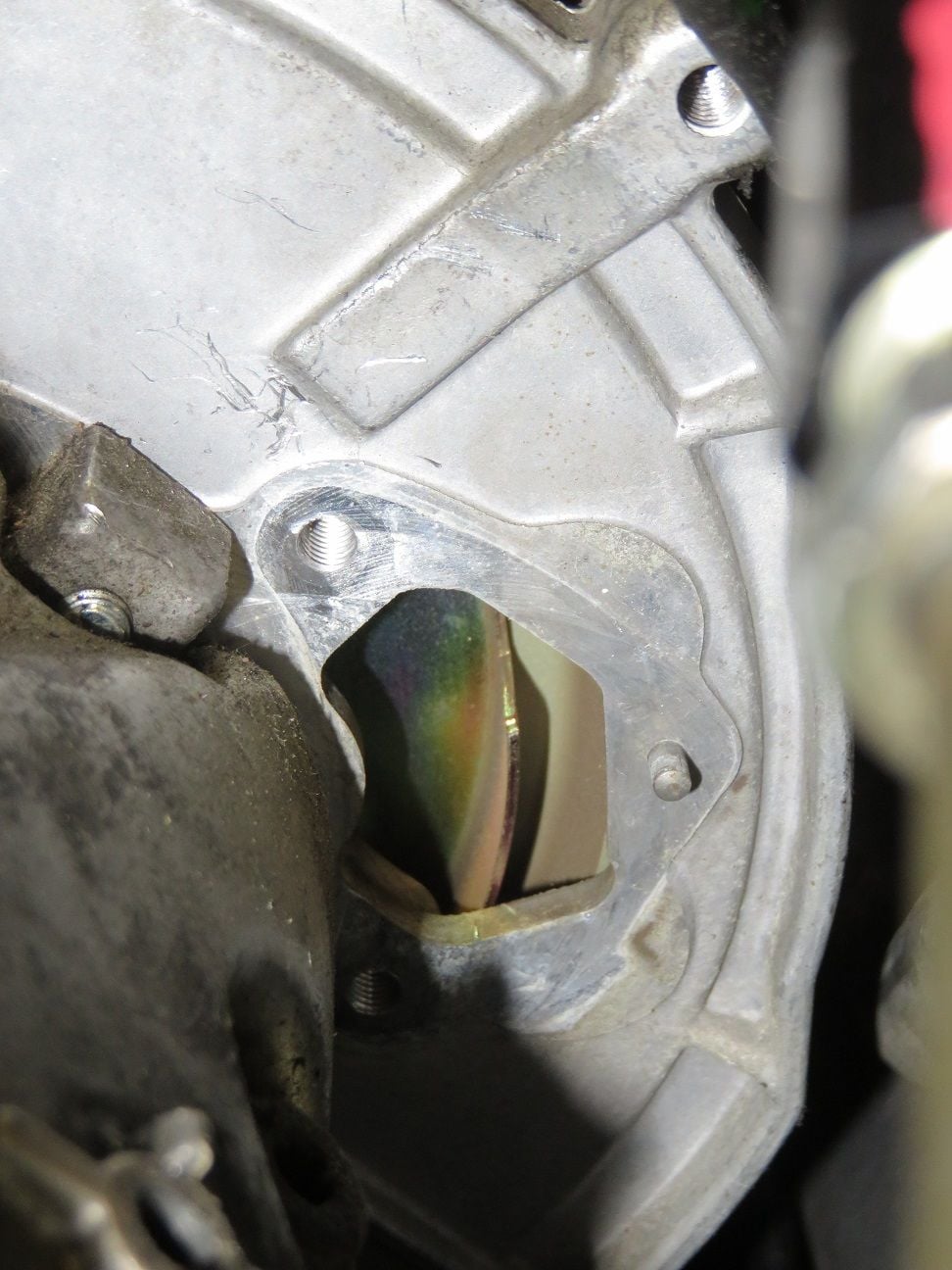
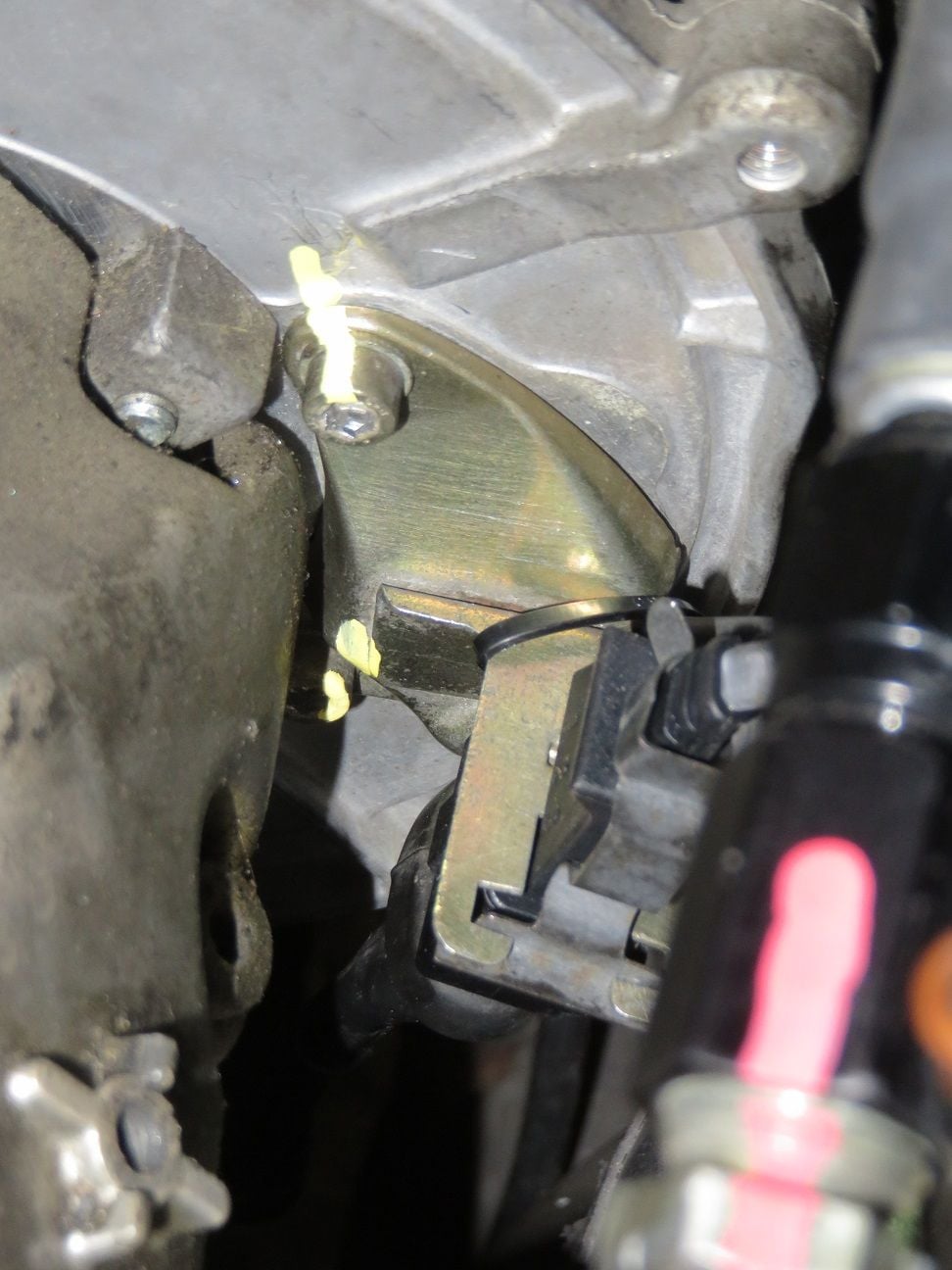
Old hall sensor removed, and this is what you see then:
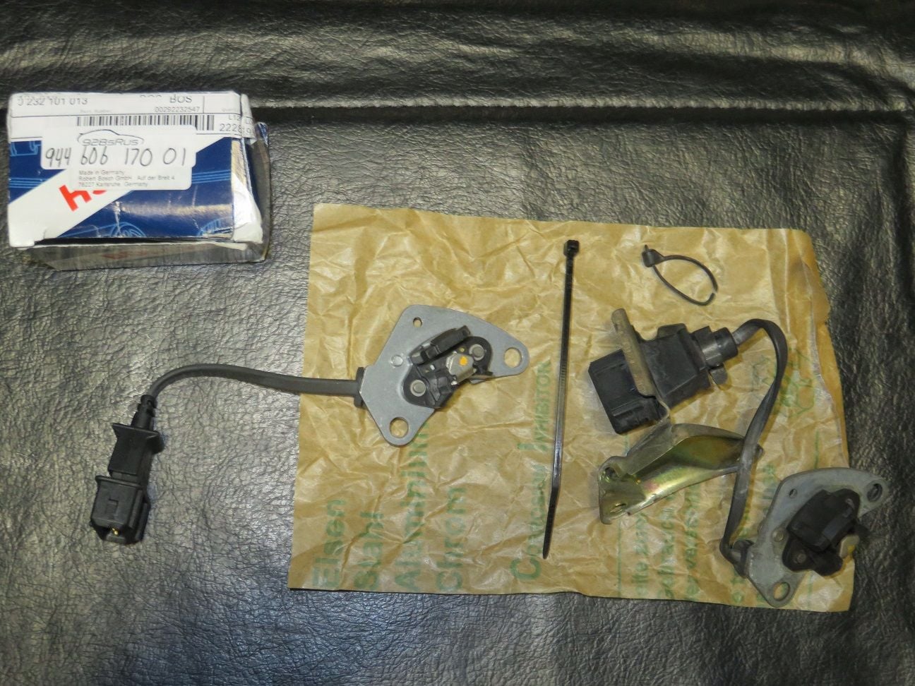
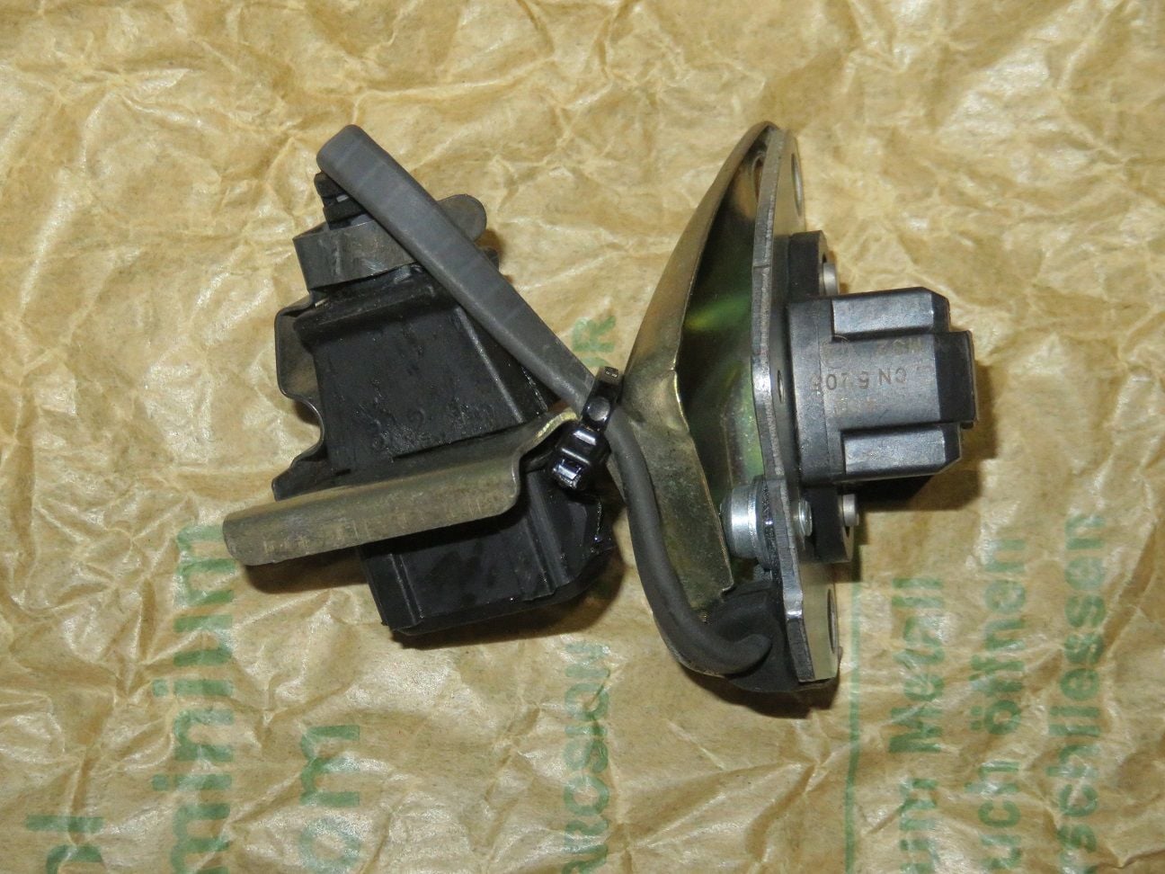
New on the left hand side, and old hall sensors:
Using worf928 tips, so to get the shorter pigtail from the new hall sensor put correctly in place. Tight, but it all fits:
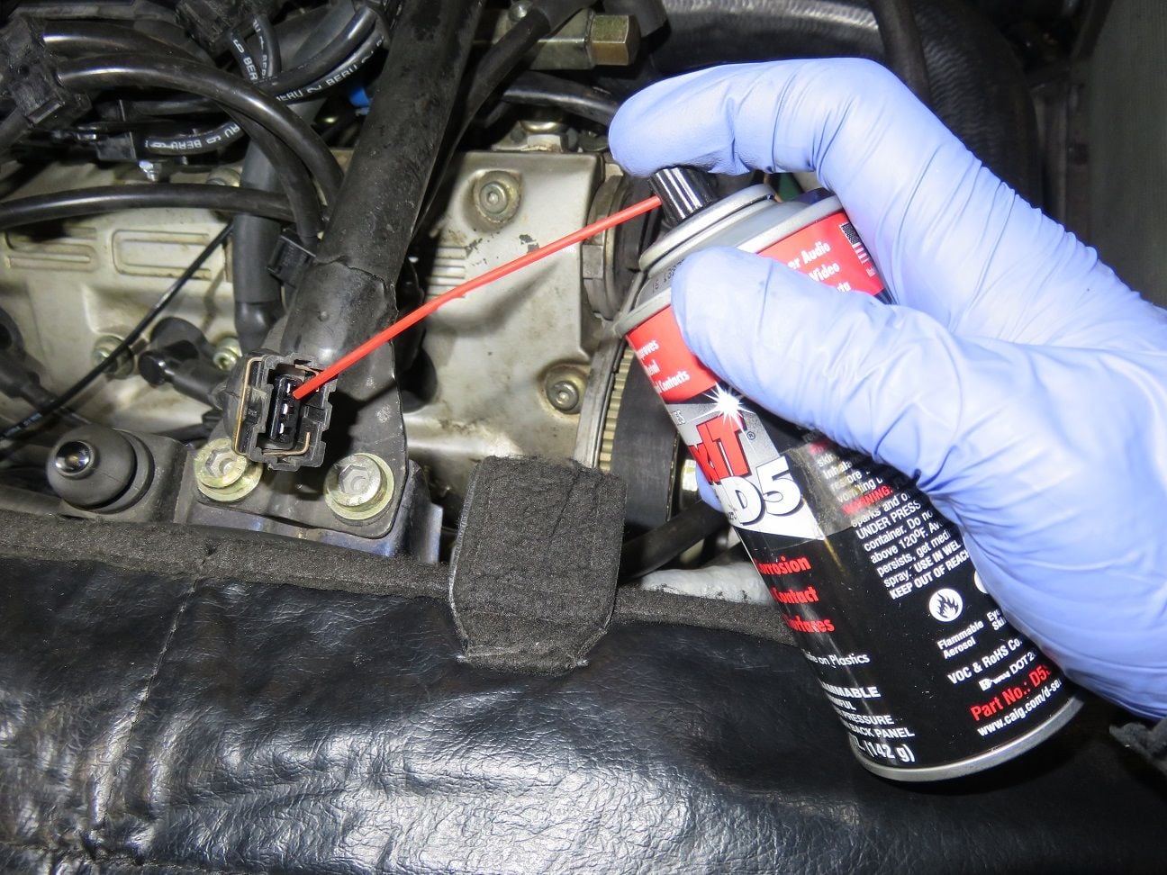
The obligatory DeoxIT use:
And new hall sensor put in place and torqued down:
Last edited by Arnoud; 04-01-2019 at 07:44 PM.
Reason: Typo's.
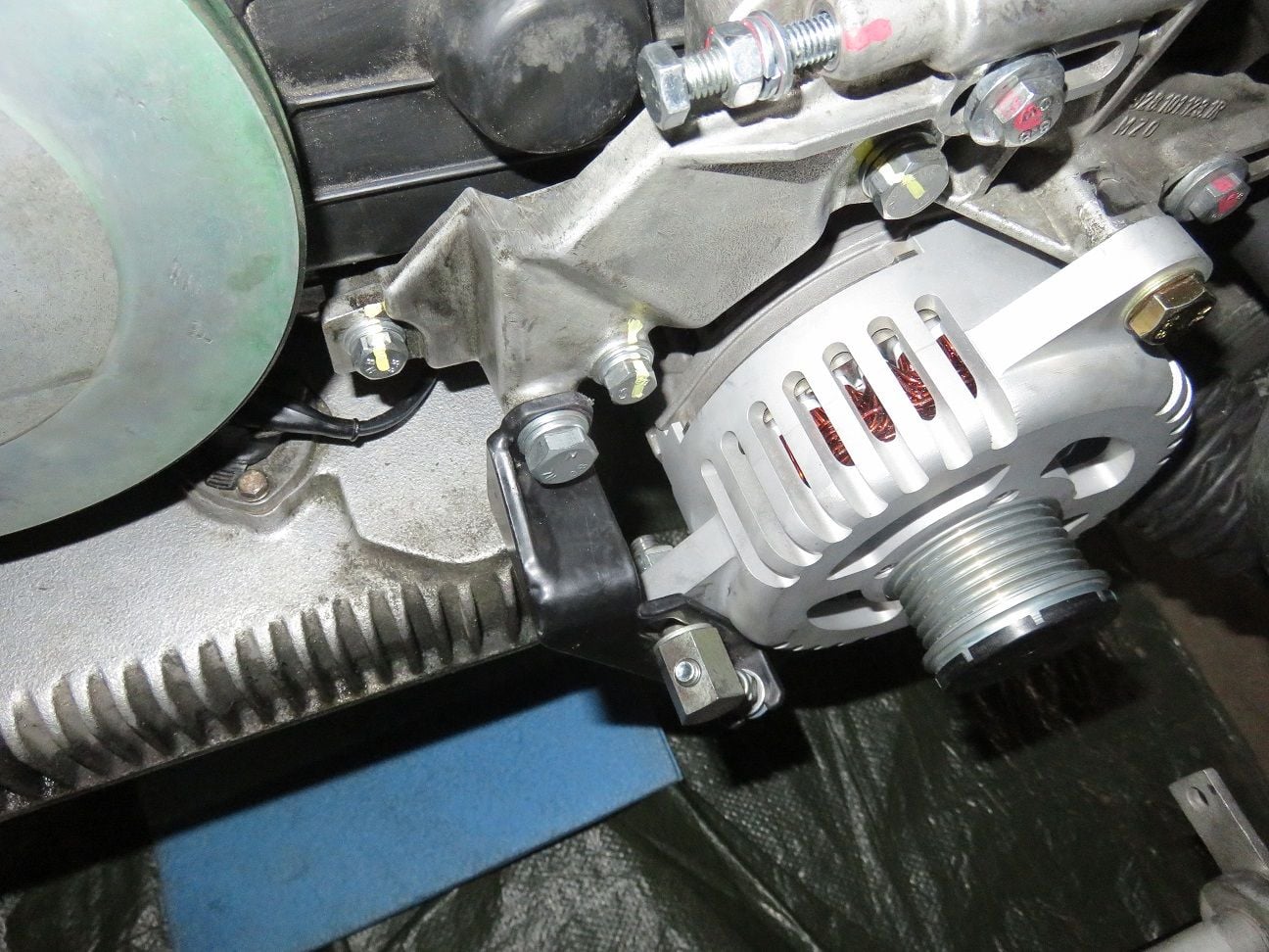
WYAIT: time to install that very nice Greg Brown alternator.
I had the very nice Greg Brown alternator being in a box for 2+ years now, so time to install that now too!
Removing the stock alternator, still looking in a rather good shape (I had cleaned and serviced it, during April 2014):
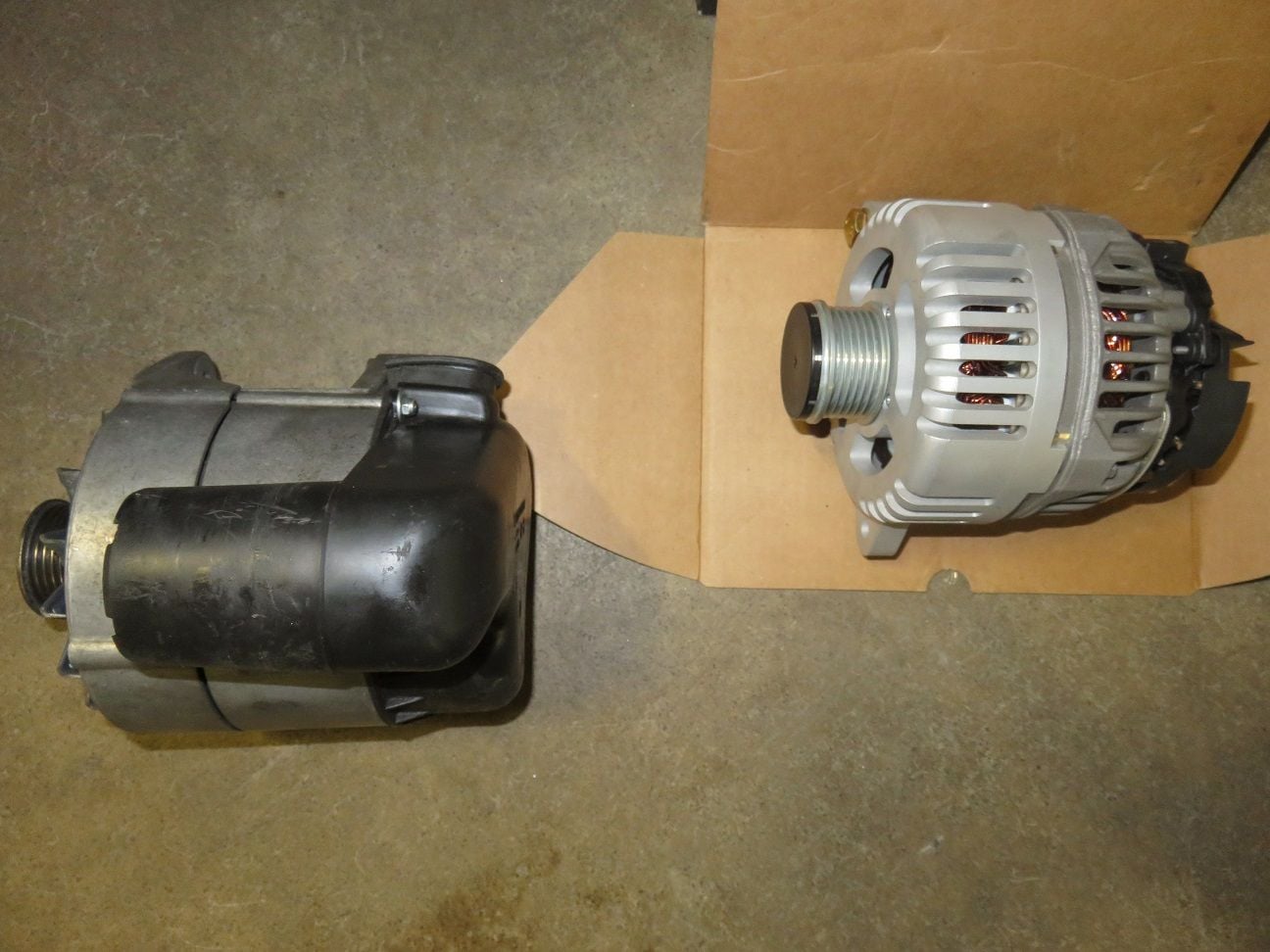
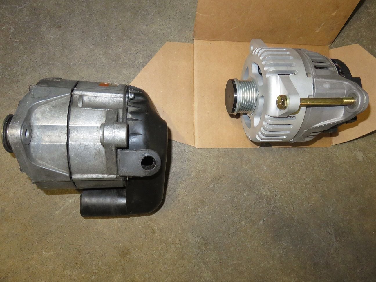
Comparing the stock alternator on the left, with the new Greg Brown alternator:
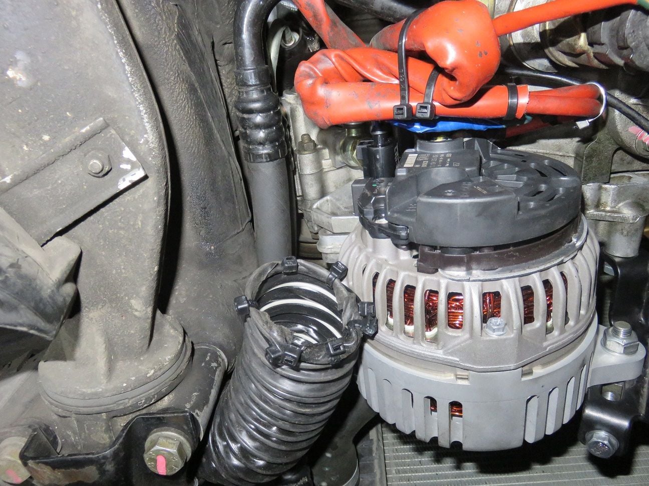
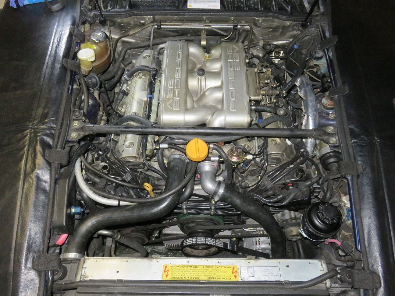
Very easy to put in place: perfect fit. Just attaching the blue field wire and more or less almost done:
View from the front: looking very good and totally belonging in there (still needed to add the belt and torque the bolts here, hence no yellow torque paint marks yet):
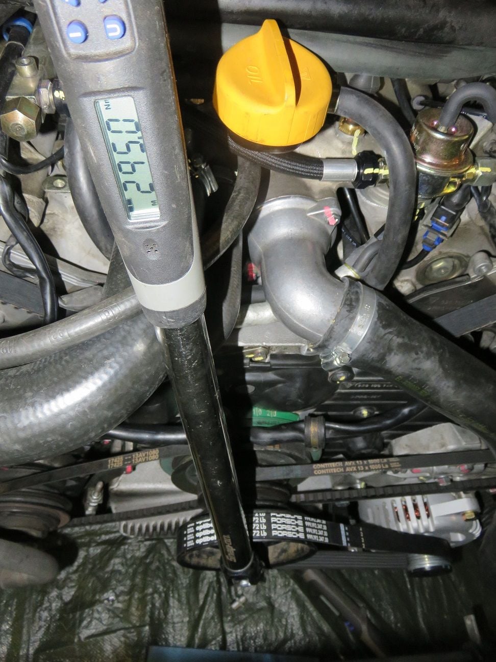
Torquing the crank bolt to 295 Nm, easy enough with just a large 1/2" torque wrench:
Then I decided to do one final timing measurement, before closing up the upper timing covers. As before, I span the engine by using the starter several times, and then moved to 0 degree TDC. Tension is still all correct:
And still 0 degree on the PS 1-4 bank:
Now it measured in between 0 and +1 degree on DS 5-8 bank, I decided to leave it like that:
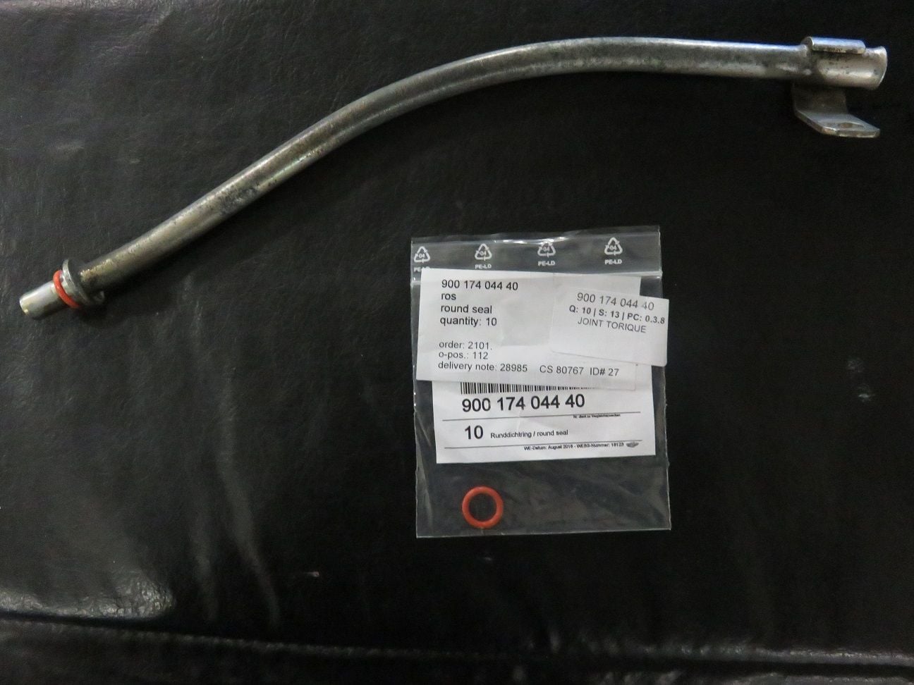
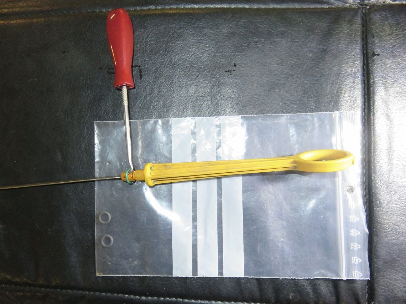
Final touches: changing out the now 25 year old dipstick O-rings:
Wonder why my came originally from the factory with a green colour top O-ring...who knows...
And finally all done, apart from the fan housing:
Last edited by Arnoud; 04-01-2019 at 07:38 PM.
Reason: Typo's.
This evening I therefore performed a renewed compression test, here are my findings as done with a stone cold engine - but this time I did put the throttle pedal "to the floor" when cranking the engine.
For each and every cylinder I cranked the engine for eight (8) audioable cycles and then took the reading: Cylinder 5: 202 PSI Cylinder 6: 207 PSI Cylinder 7: 202 PSI Cylinder 8: 200 PSI
Re-testing cylinder 5 (just so to make sure that during all this cranking the starter motor etc. did not got weaker - and it did not): still 202 PSI.
I think the above now reads all good, what does the 928 brain trust thinks?
Arnoud,
In terms of consistency the indicated compression pressures are excellent so nothing wrong with your motor and that considering these are cold numbers. The interesting bit is the clear and obvious difference between the drivers side cylinders and the passenger side items. I note that for whatever reason you set both sides cam timing at zero but this is not quite correct as the passenger side bank [as I recall] is supposed to be retarded by two degrees to compensate for the cold engine effect so maybe that could explain the small but apparent difference between banks.
That being said I am puzzled in that if one bank is relatively advanced I would expect that bank to give slightly higher compression numbers during the standard compression test procedure and your numbers are the opposite way round. To be clear I doubt you would even notice anything in real world performance terms but given the lengths you have gone to it would be interesting to understand and/or resolve this "apparent" anomaly.
If the logic is flawed hopefully someone will correct that

 03-04-2019, 11:43 PM