When you click on links to various merchants on this site and make a purchase, this can result in this site earning a commission. Affiliate programs and affiliations include, but are not limited to, the eBay Partner Network.
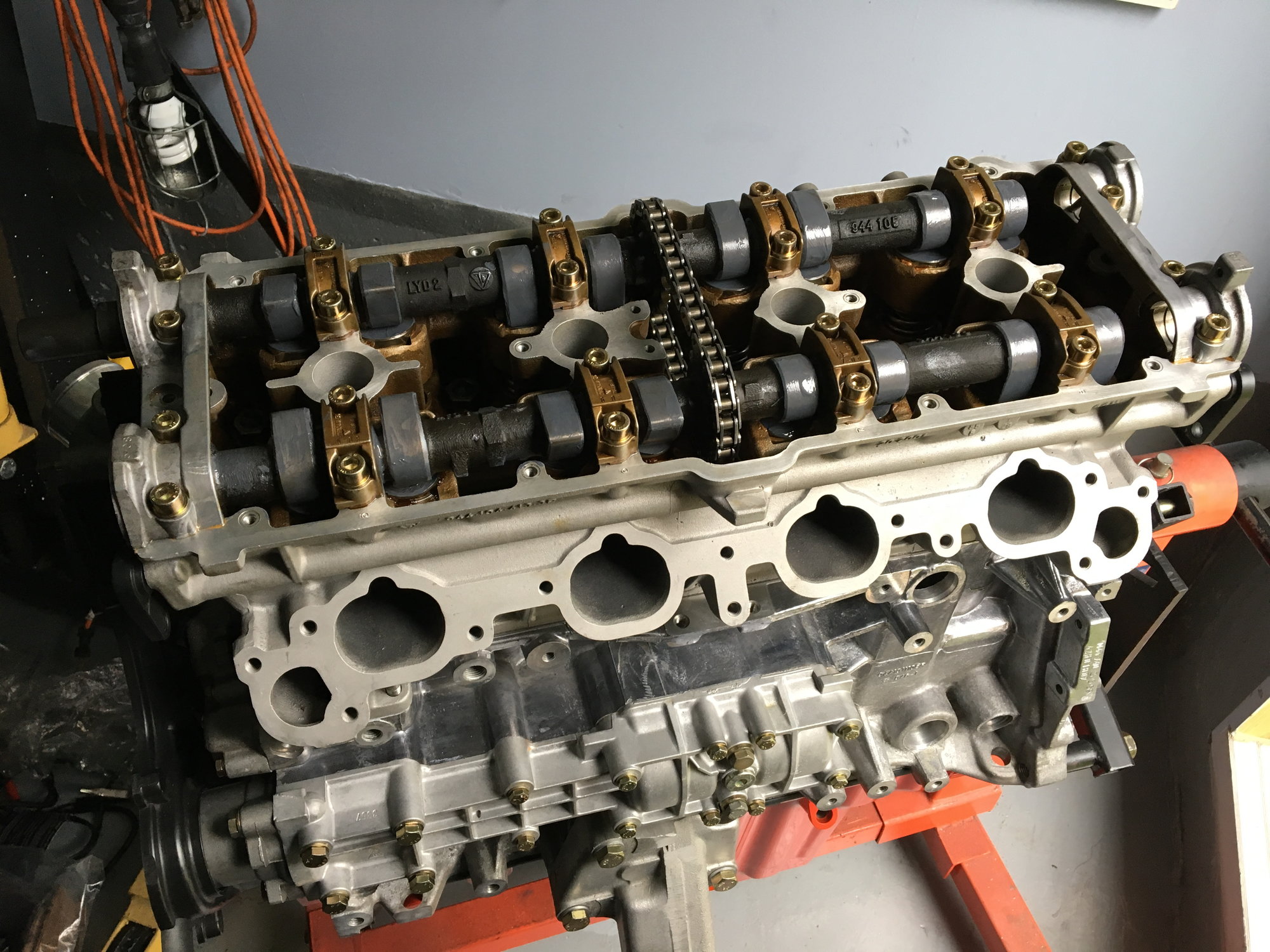
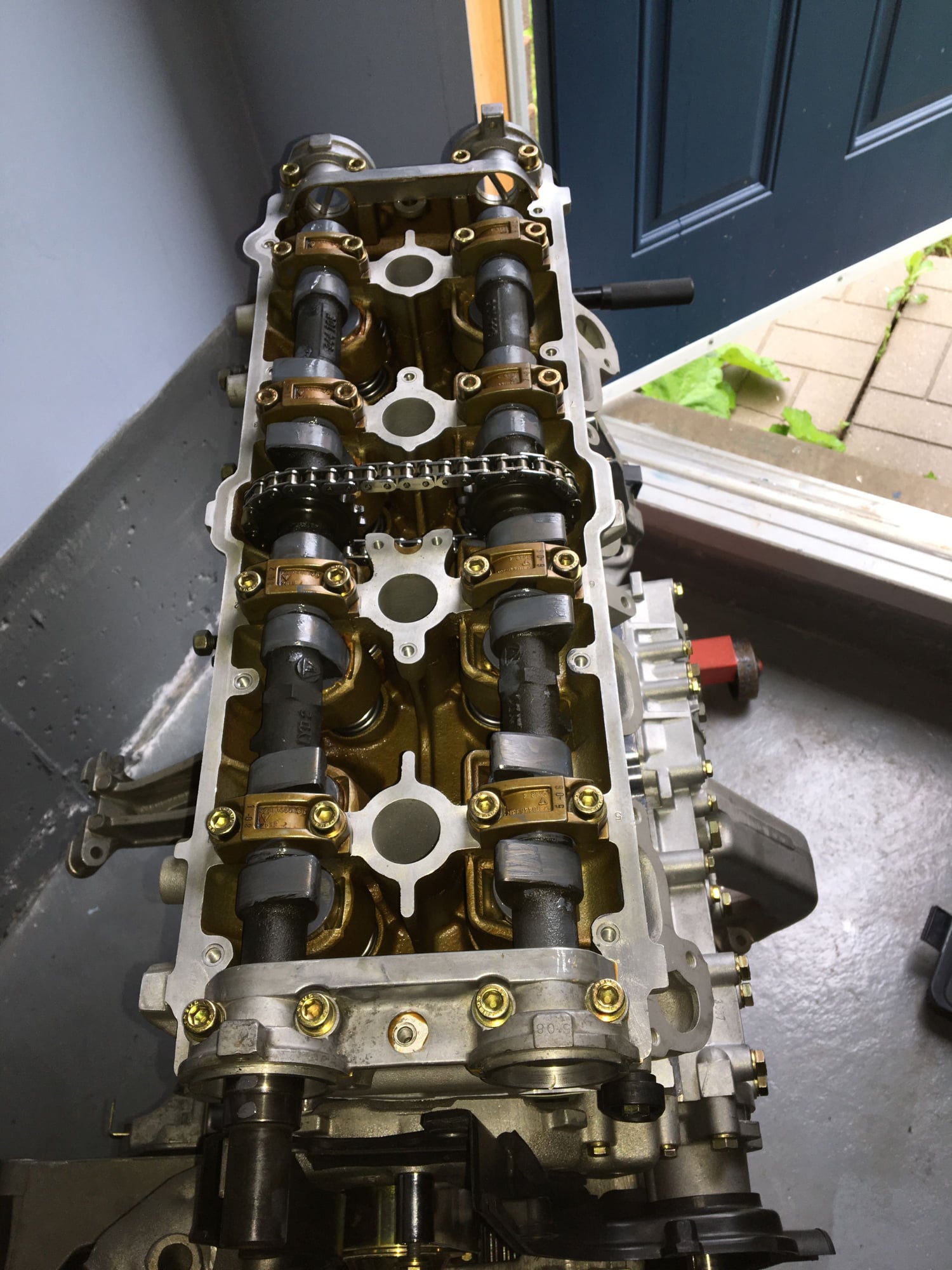
Once the cylinder head was on, next up was the camshafts. I had my cams reground and re-treated to deal with some minor pitting on a few of the lobes. It took a while to find the right shop for this... Installation was pretty straightforward. There is a pointed “lug” near the sprocket on each cam. When the two shafts are correctly “keyed” to each other, the timing chain will show seven outer links between the lug points, and the points will be 113 mm apart.
Once the chain was correctly located on both shafts, I smeared every contact surface with copious amounts of assembly lube (lobes, tappets, bearing surfaces). I positioned the engine ~45 degrees before TDC for cylinder 1 to make sure the pistons were out of the way in case of a mistake on my part. Next, it was a matter of laying the shafts carefully into the bearing bosses and then installing the bearing caps and carefully tightening them into position (I turned each cap screw a half turn at a time, in an alternating sequence). There are assembly tools shown in the shop manual that would considerably speed & simplify the part of the job, but I think just being very slow and steady also gets the cams safely into position without a lot of excess bending stress. The cams were installed with those pointed lugs aimed upwards, which corresponds approximately to the position for cylinder 1 TDC. When it comes time to install the belts and time things, I will of course have to move the crank to TDC…
The bearing caps are all numbered and maintaining the original location and orientation is mandatory, as they were line bored originally.
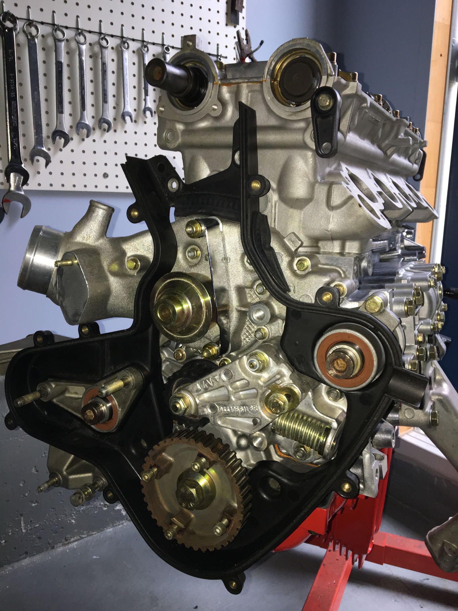
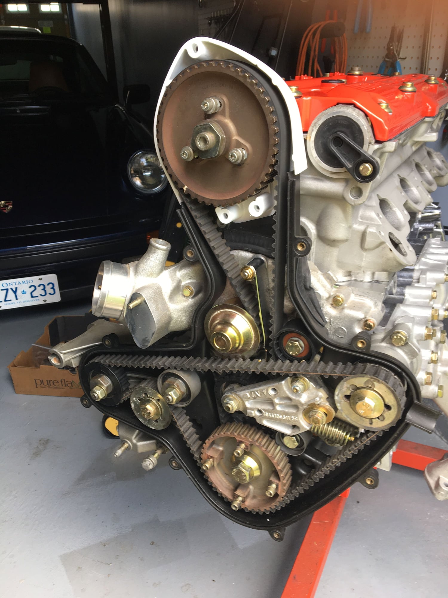
I started with the ancillary bits on the front of the engine, with the water pump first.
I will continue with the rest of the front-of-engine parts (balance shaft sprockets, rollers etc.) as well as the timing chain tensioner, and then I should be ready to put the belts on and do the final cam timing.
Creeping along slowly... I have installed the cam shaft seal and the sealing plugs for the three ends where the camshafts do not protrude out of the head.
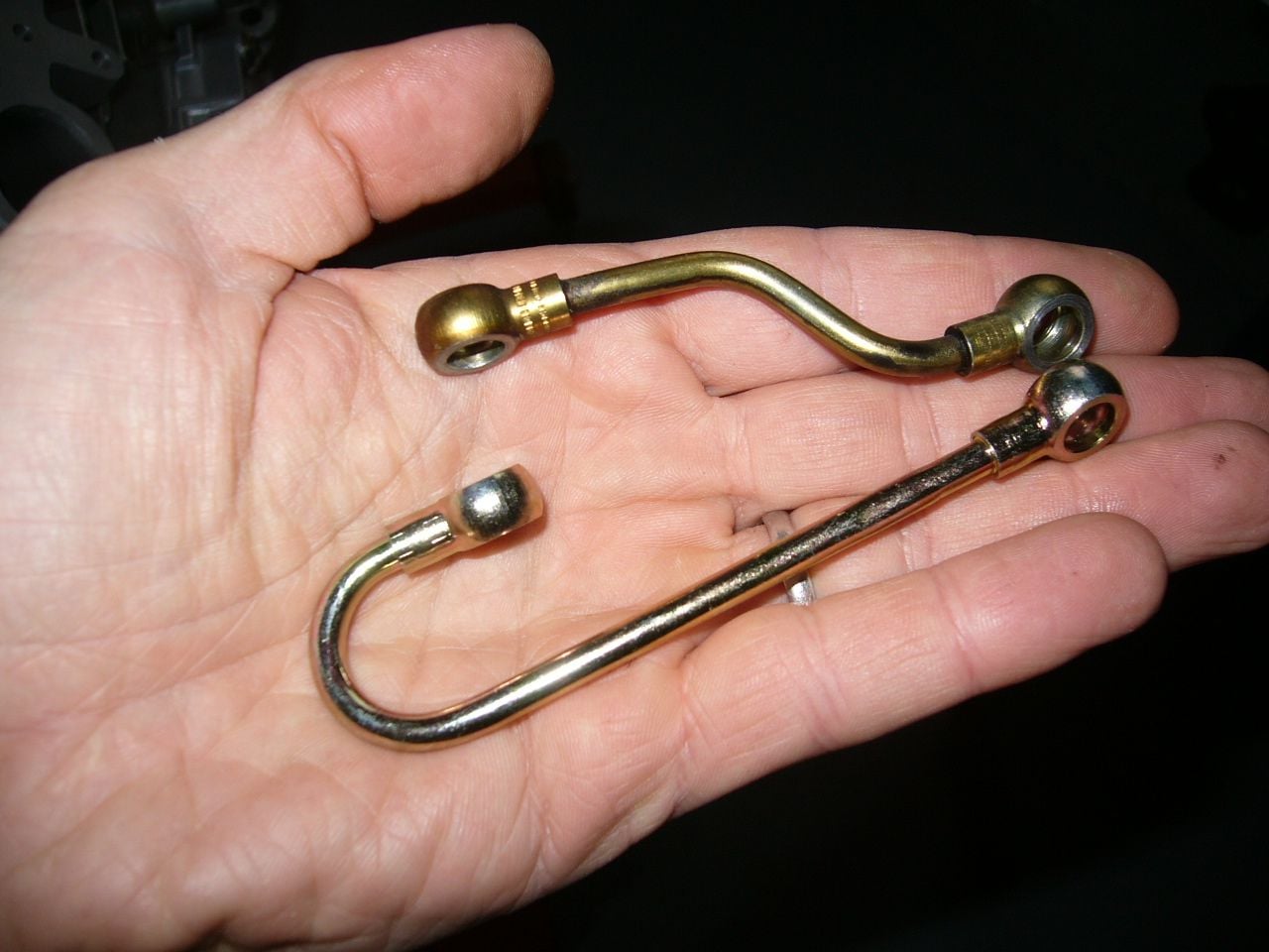
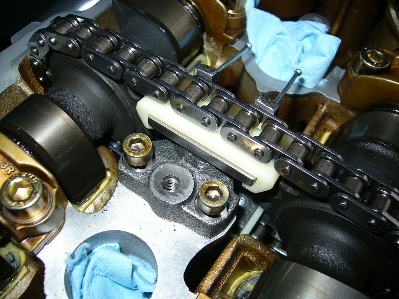
Next up was the cam chain tensioner. The plastic wear pads are the significant additional maintenance item for the 16V cars. Apparently, it is possible to replace just the plastic pads, but I went for a new tensioner and new feed pipe. The new feed pipe had a different, simpler shape than the original, which I believe was a running update at some point. Fit perfectly (with new banjo bolts and sealing washers).
Everything looks OK so far, the next step will be to add the timing belt and then time the cams.
Just to add as reference: The old chain tensioner feed line "S-bend" versus the new style - single "J-bend":
Also, for those installing the chain tensioner in the future, a pair of finishing nails works perfectly to temporarily hold the tensioner in the fully compressed position allowing you to get in place between the chain...
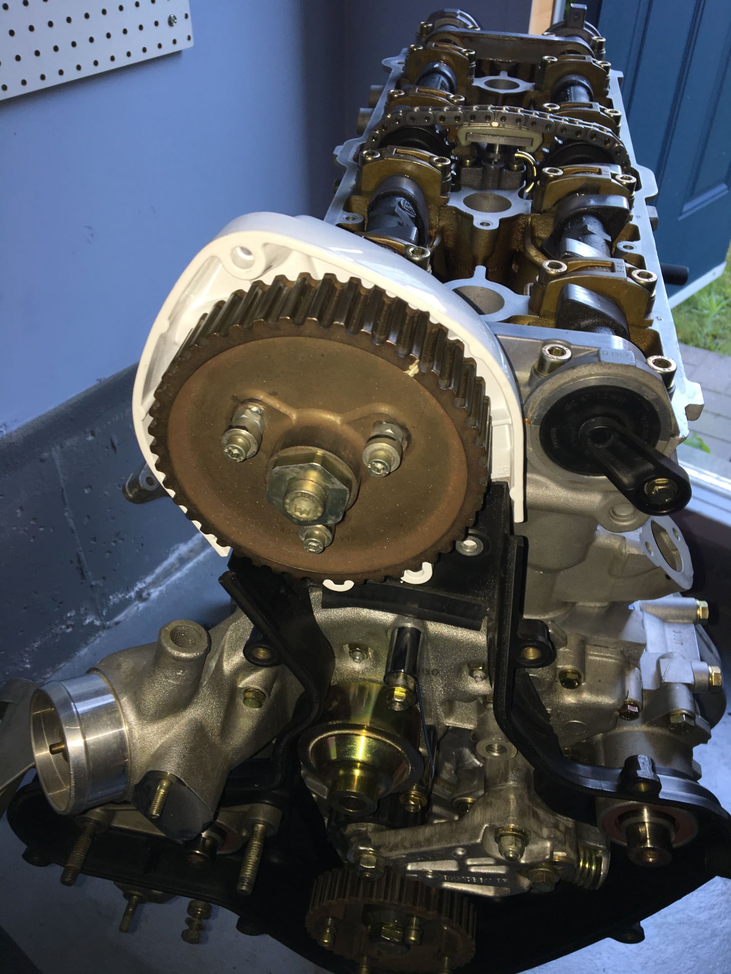
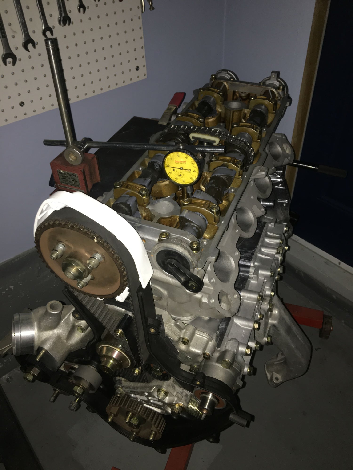
I think I am done with the cam timing. I will check it again “from scratch” just to make sure. The goal for stock timing on a 944S is to have 1.4 mm of valve lift on the intake valve with that cylinder’s piston at TDC. This is made possible by the construction of the cam sprocket, which is attached to a “spider” which is keyed tightly to the exhaust camshaft. The sprocket itself is attached to the spider through three slots, which allow the sprocket to be rotated somewhat relative to the camshaft.
I installed the cams in the approximate position they would be at TDC for firing of cylinder one, moved the crank to TDC and then installed the belt. After slightly loosening the cam sprocket center bolt and the three bolts that pass through the slots, the crank is turned backward slightly until the cam sprocket has turned to the limit of the play allowed by the slots. The bolts are re-tightened and then the engine is rotated forward until the intake valve shows 1.4 mm lift (via a dial indicator). The bolts are then slackened and then the crank is rotated further forward, until the piston reaches TDC (and since the bolts are loose, the camshafts don’t move during this stage, just the sprocket). At that point the cam sprocket mounting bolts are re-tightened and (hopefully) the result is 1.4 mm of valve lift corresponding to TDC.
The first time I did it, I ran out of room on the slots (I was still a smidgen shy of TDC when I got to the end of the available travel). I had to move the timing belt one tooth “ahead” on the sprocket and re-do the exercise, which seemed to work well. I will re-check everything tonight with fresh eyes to verify.
The best way to do this is with two dial gauges, one on the piston, the other on the intake valve tappet. I used one gauge, so I had to continually change position. It is very easy to accurately see TDC with the gauge I have (the needle instantly reverses direction). The gauge I used shows one complete revolution of the needle for 1 mm of travel, and that resolution was sensitive enough to show TDC very accurately.
Interesting! I didn't realize how involved setting the cam timing was in the 944S engine (I also have a 944S). In all of the BMW V8's that I've rebuilt, the cams had clear timing marks and the flywheel had an obvious TDC mark so it was very easy to set timing, even when putting together an engine from scratch.
I think I am done with the cam timing. I will check it again “from scratch” just to make sure. The goal for stock timing on a 944S is to have 1.4 mm of valve lift on the intake valve with that cylinder’s piston at TDC. This is made possible by the construction of the cam sprocket, which is attached to a “spider” which is keyed tightly to the exhaust camshaft. The sprocket itself is attached to the spider through three slots, which allow the sprocket to be rotated somewhat relative to the camshaft.
I installed the cams in the approximate position they would be at TDC for firing of cylinder one, moved the crank to TDC and then installed the belt. After slightly loosening the cam sprocket center bolt and the three bolts that pass through the slots, the crank is turned backward slightly until the cam sprocket has turned to the limit of the play allowed by the slots. The bolts are re-tightened and then the engine is rotated forward until the intake valve shows 1.4 mm lift (via a dial indicator). The bolts are then slackened and then the crank is rotated further forward, until the piston reaches TDC (and since the bolts are loose, the camshafts don’t move during this stage, just the sprocket). At that point the cam sprocket mounting bolts are re-tightened and (hopefully) the result is 1.4 mm of valve lift corresponding to TDC.
The first time I did it, I ran out of room on the slots (I was still a smidgen shy of TDC when I got to the end of the available travel). I had to move the timing belt one tooth “ahead” on the sprocket and re-do the exercise, which seemed to work well. I will re-check everything tonight with fresh eyes to verify.
The best way to do this is with two dial gauges, one on the piston, the other on the intake valve tappet. I used one gauge, so I have to continually change position. It is very easy to accurately see TDC with the gauge I have (the needle reverses direction). The gauge I used shows one complete revolution of the needle for 1 mm of travel, and that resolution was sensitive enough to show TDC very accurately.
It's been a while, but I could have sworn that 2 x dial gauges was mandatory, not optional.
For sure it is much easier and more direct to have two dial gauges for this job.
The essential goal is to have 1.4 mm of intake valve lift precisely at TDC (the number is different for S2s and 968s BTW). Having two gauges allows one to monitor both parameters simultaneously. With one gauge, I had to first get the 1.4 mm of valve lift, and then move the crank to TDC (while the cam sprocket was disengaged from the shaft, so that the valve positions would not change). The problem is that by moving the dial gauge from the valve tappet over to monitor the piston position, I could not “see” (via movement on the dial) if anything happened to the valve positions. It LOOKED like everything remained motionless, but one can’t be sure…
Hence, it is necessary to check everything again after one THINKS it is all done. The way to check is to rotate the crank a few times and then (using the dial gauge) get back to 1.4 mm of intake valve lift…
Now, it is necessary to verify that the crank is also at TDC at the same position. My first thought was to use the dial gauge and if the crank is really at TDC, than just a slight nudge on the crank in either direction would show the needle deflecting in opposite directions. However, this will only work if you are at TDC, otherwise, you don’t really know. If the crank is slightly behind TDC, then you can see this by rotating the crank forward until the needle direction changes. If you are out in the other direction, it is not so helpful, because you would need to rotate the crank opposite to the normal rotating direction, which the manual constantly says is a no-no.
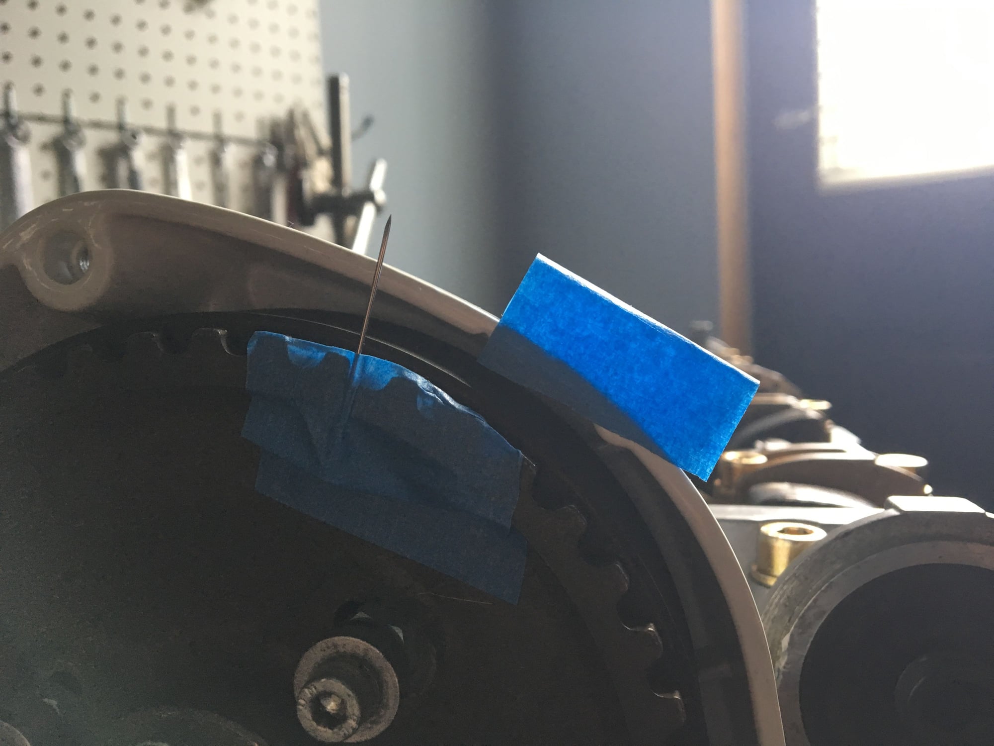
A better way (what I intend to do to check) is to attach a needle temporarily to the cam sprocket, then use the dial gauge to get perfectly on TDC and then carefully apply a strip of tape to the surrounding housing so that the edge of the tape exactly lines up with the needle. This is a very accurate way to mark TDC. Then one can repeatedly rotate the crank to the position of 1.4 mm valve lift (indicated using the gauge) and see if at that exact point the needle lines up. If so, great! If not, then the process of timing will have to be repeated and since that involves moving the cam sprocket relative to the shaft, that needle and tape mark is now irrelevant and it all has to be repeated, which shows that using two dial gauges is definitely the more efficient way to go. However, with lots of time and patience one gauge will suffice. I will see how many times I end up going through the process until I am there… I hope I am already, but I will see. I will attach a picture of what I described when I check my work, which will likely be this weekend.
Actually, while I was typing this, I remember a video I had watched of a German master mechanic (they do take their trades seriously…) timing an S2… He didn’t use a gauge for TDC either, rather he had an assistant spot the TDC reference on the flywheel (engine was in car). Pretty good video… it is in German, but has English subtitles. I found the link:
So I managed to do the cam timing check exercise and I am now happy that I have it really perfect.
Here is the “marker” I was describing in the prior post.
The crank is still a little before TDC. At TDC, the needle on the cam sprocket aligns with the edge of the tape marker. What took me the longest was getting the tape marker right, so that the edge would fully align with the needle. Also, it was important to view the edge of the tape straight on, to avoid parallax issues. The way I ended up doing this was to have two layers of tape, with a gap between. With sunlight coming from behind, it was easy to see when my viewing position was straight-on (since the tape is a little translucent). Once I had this figured out, I went through a bunch of test cycles rotating the crank to TDC using the dial gauge to identify when I was at TDC and then confirming that the needle indicator was also exactly showing TDC too. Eventually I got everything “dialed in” and I was able to locate TDC with the needle with total precision. It took me probably 45 minutes to get to this point, more reason why having two dial indicators would be the more practical way to go!
Anyway, at that point I set the dial indicator on one of the #4 cylinder intake valve tappets and verified the valve lift at TDC. I repeated this a bunch of times (with multiple rotations of the crank, just to be certain the belt was totally “settled in”). I ended up getting bang-on 1.4 mm within +/- 0.02, which is well within the +/- 0.10 specified in the factory manual. So, I am now totally happy with the cam timing.
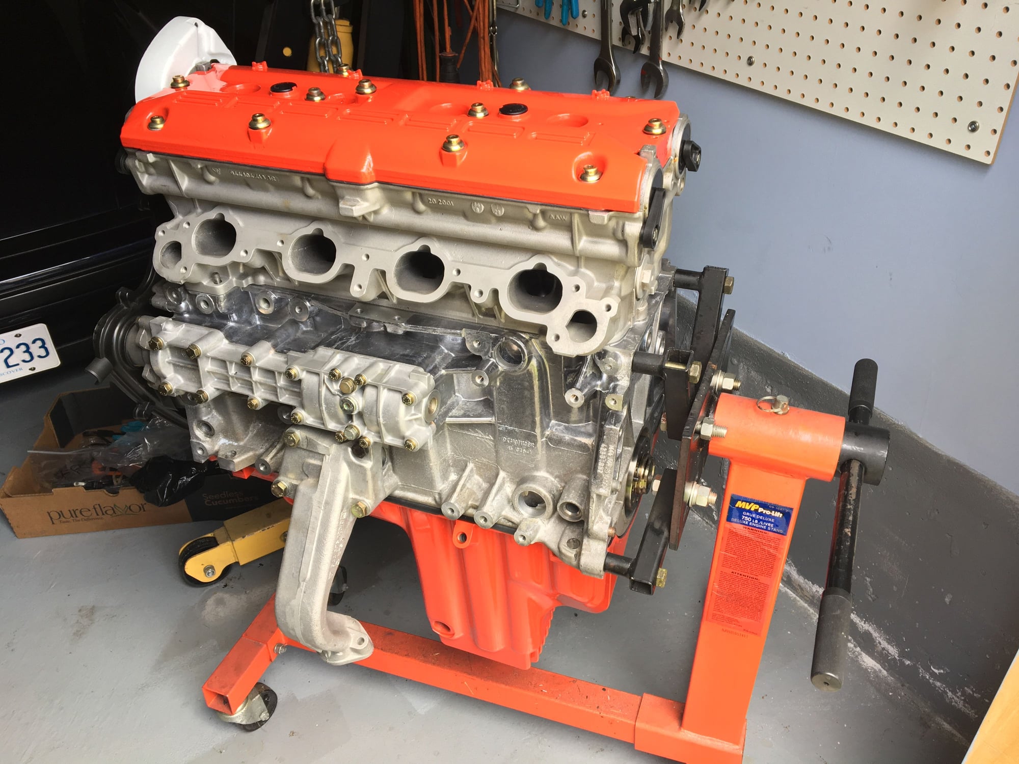
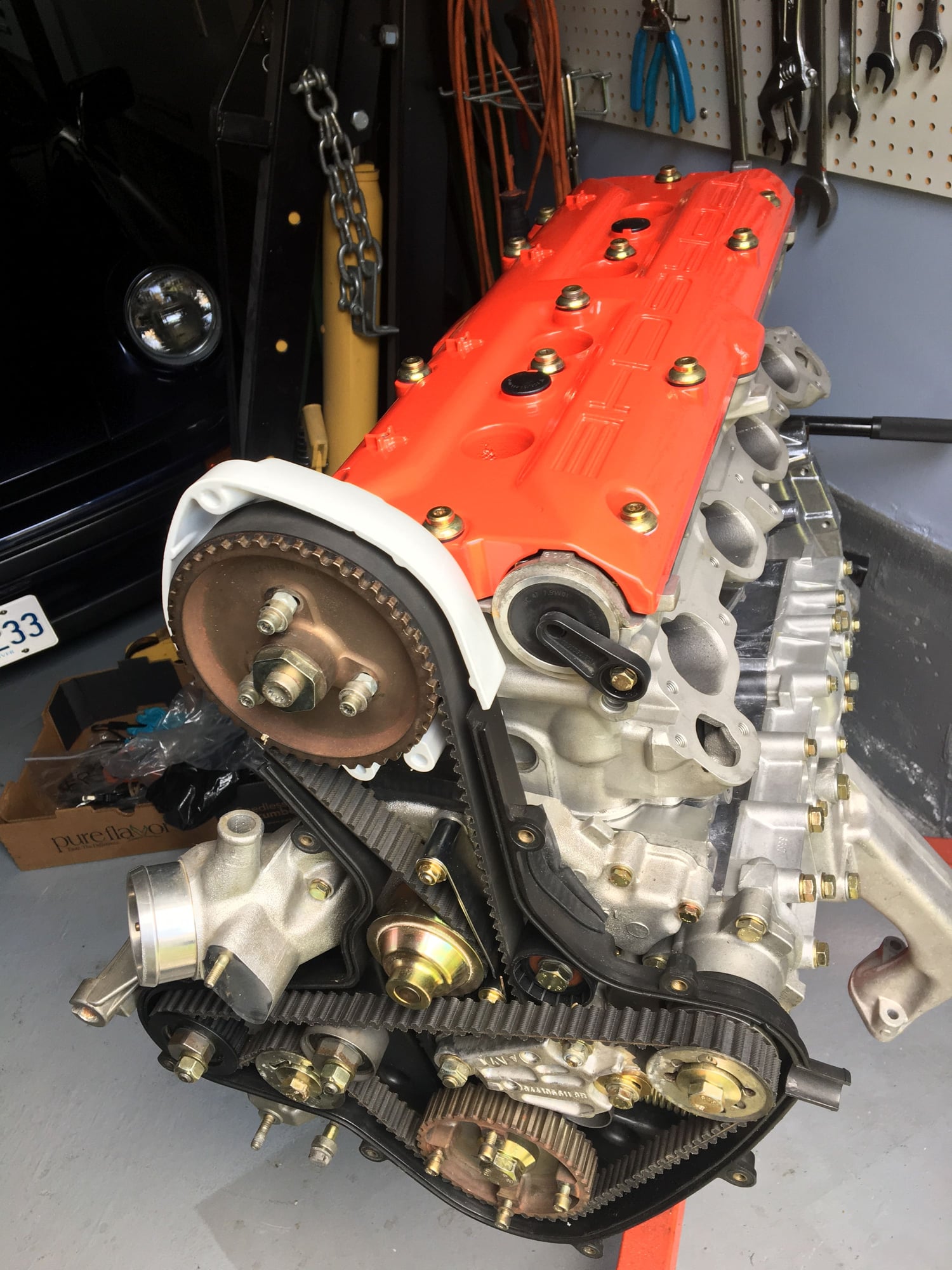
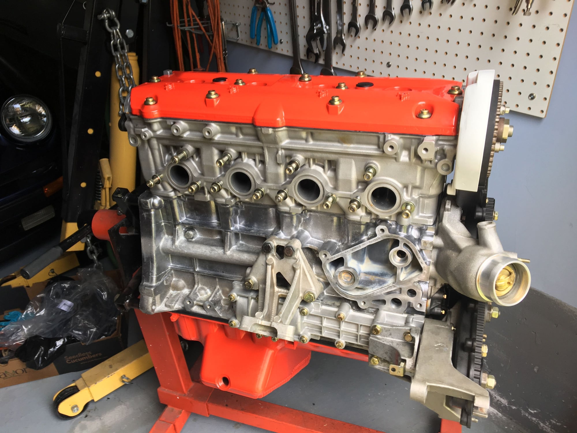
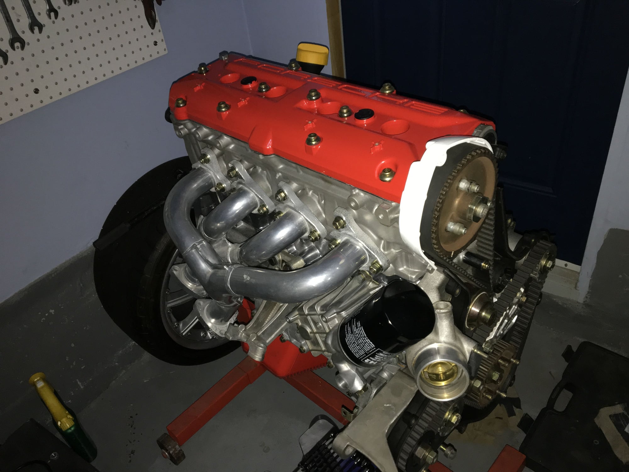
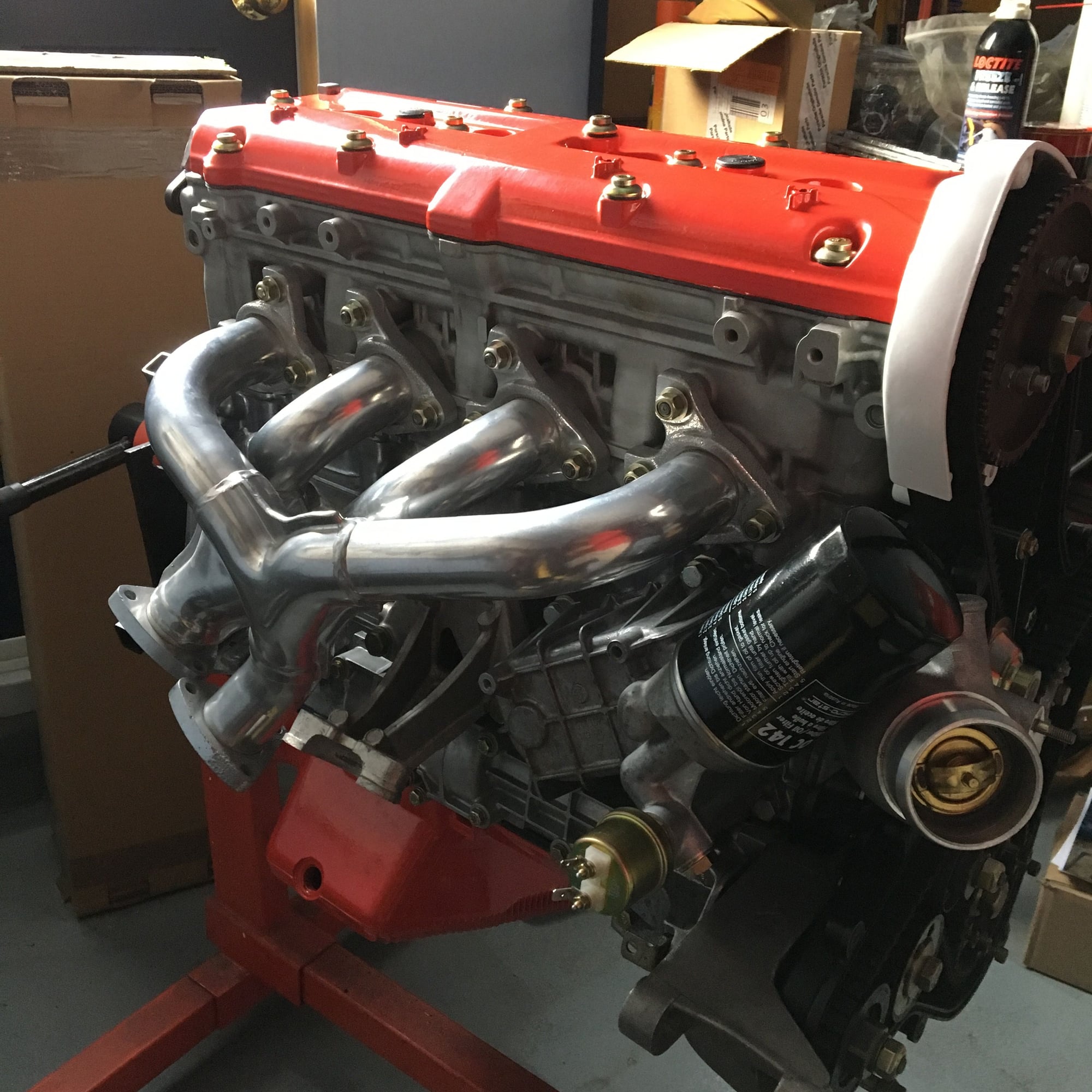
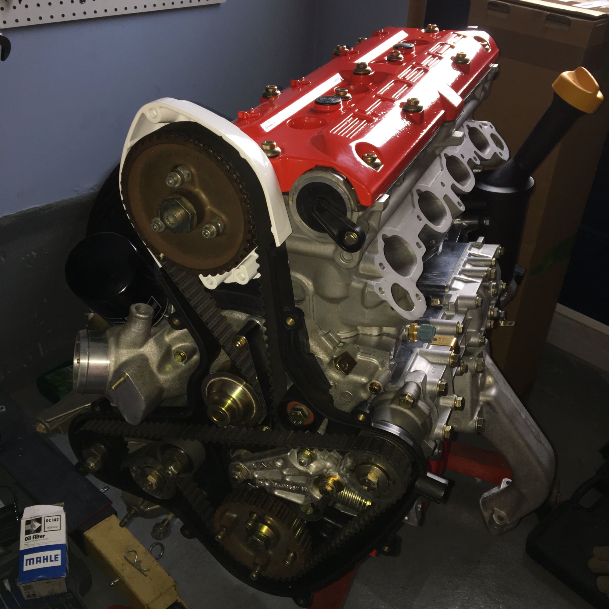
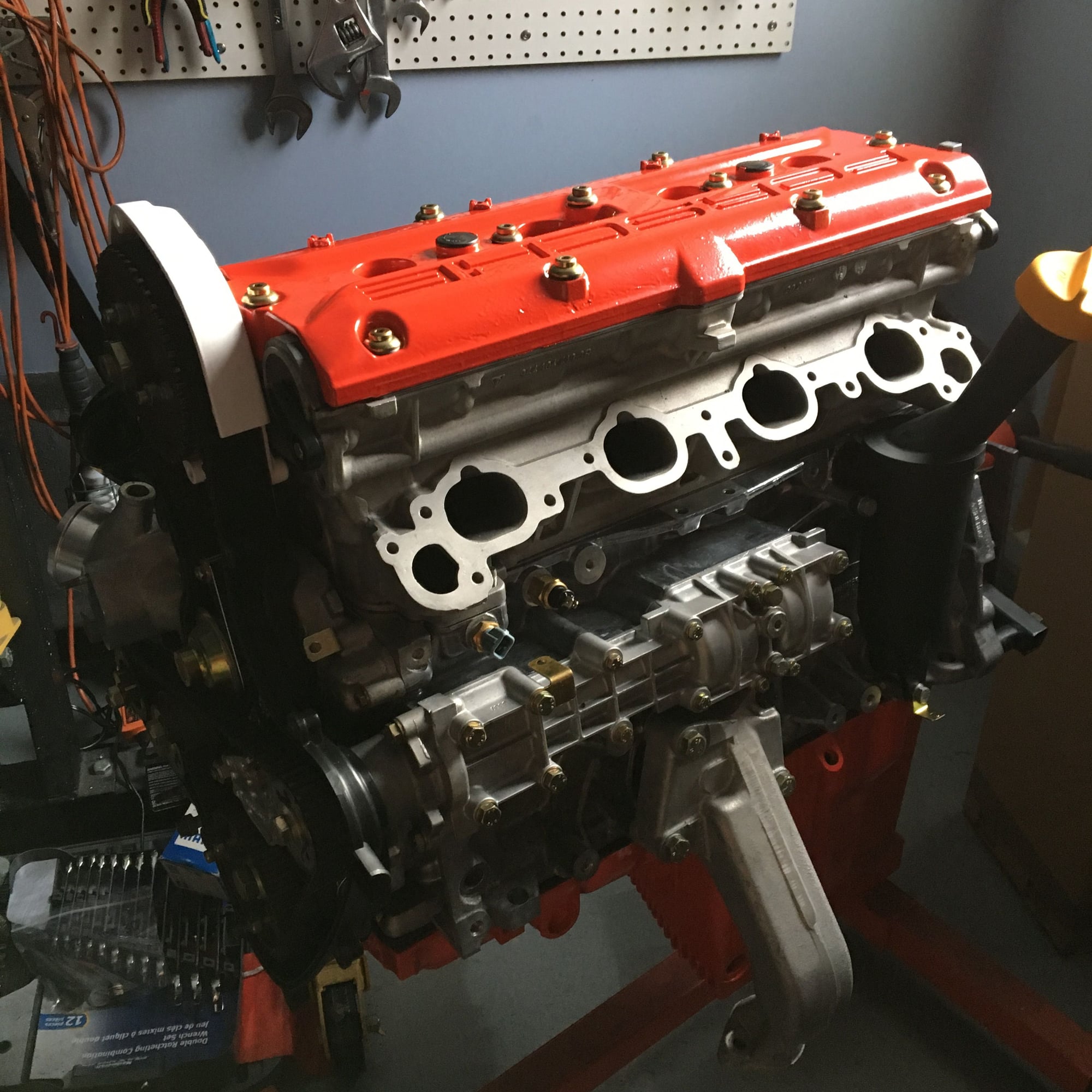
Having finished with that, I went ahead and mounted the balance shaft belt, which was pretty straightforward and then closed off the top of the engine with the cam cover, which I had powder coated red, along with the oil sump.
Last edited by 500; 11-28-2017 at 11:55 AM.
Reason: Typo... "not" should have been "now"
So I managed to do the cam timing check exercise and I am not happy that I have it really perfect.
Here is the “marker” I was describing in the prior post.
The crank is still a little before TDC. At TDC, the needle on the cam sprocket aligns with the edge of the tape marker. What took me the longest was getting the tape marker right, so that the edge would fully align with the needle. Also, it was important to view the edge of the tape straight on, to avoid parallax issues. The way I ended up doing this was to have two layers of tape, with a gap between. With sunlight coming from behind, it was easy to see when my viewing position was straight-on (since the tape is a little translucent). Once I had this figured out, I went through a bunch of test cycles rotating the crank to TDC using the dial gauge to identify when I was at TDC and then confirming that the needle indicator was also exactly showing TDC too. Eventually I got everything “dialed in” and I was able to locate TDC with the needle with total precision. It took me probably 45 minutes to get to this point, more reason why having two dial indicators would be the more practical way to go!
Anyway, at that point I set the dial indicator on one of the #4 cylinder intake valve tappets and verified the valve lift at TDC. I repeated this a bunch of times (with multiple rotations of the crank, just to be certain the belt was totally “settled in”). I ended up getting bang-on 1.4 mm within +/- 0.02, which is well within the +/- 0.10 specified in the factory manual. So, I am now totally happy with the cam timing.
Having finished with that, I went ahead and mounted the balance shaft belt, which was pretty straightforward and then closed off the top of the engine with the cam cover, which I had powder coated red, along with the oil sump.
Well, it looks good.
Something about the 16Vs that just look more like a proper engine on a stand.
Working on one for myself now but it's not even near to mount on a stand yet...
On the three cam sprocket lock down bolts....does it look like the washers lay pretty much in the same clean spot where they were previously before you tore the engine down...?
I just realized that in post #24 I said "I am not happy" in the first line when I meant "I am now happy"! Sort of changes it!!
Anyway, progress on the slow project has been even slower than usual as I have been occupied with a flurry of work on my old beater 1996 Toyota Corolla (new timing belt, engine seals, water pump, radiator, hoses, drive belts, all brake lines (hard and flexible), rebuilt brake calipers & wheel cylinders, all hard fuel lines, fuel filler and lots of bodywork (cutting out rusted metal and welding in new...)
I wanted to get all this work done before the winter hit, so the 944 project has taken even more of a back seat than usual.
I did get a bit of time to bolt on a few peripheral items: Oil cooler with all the myriad seals, new air-oil separator and I loosely fitted the ceramic coated exhaust manifolds... I may take them off when the motor goes into the car to make positioning easier. In any event, I won't torque the manifold in until the motor is mounted in the car and the rest of the exhaust is connected.
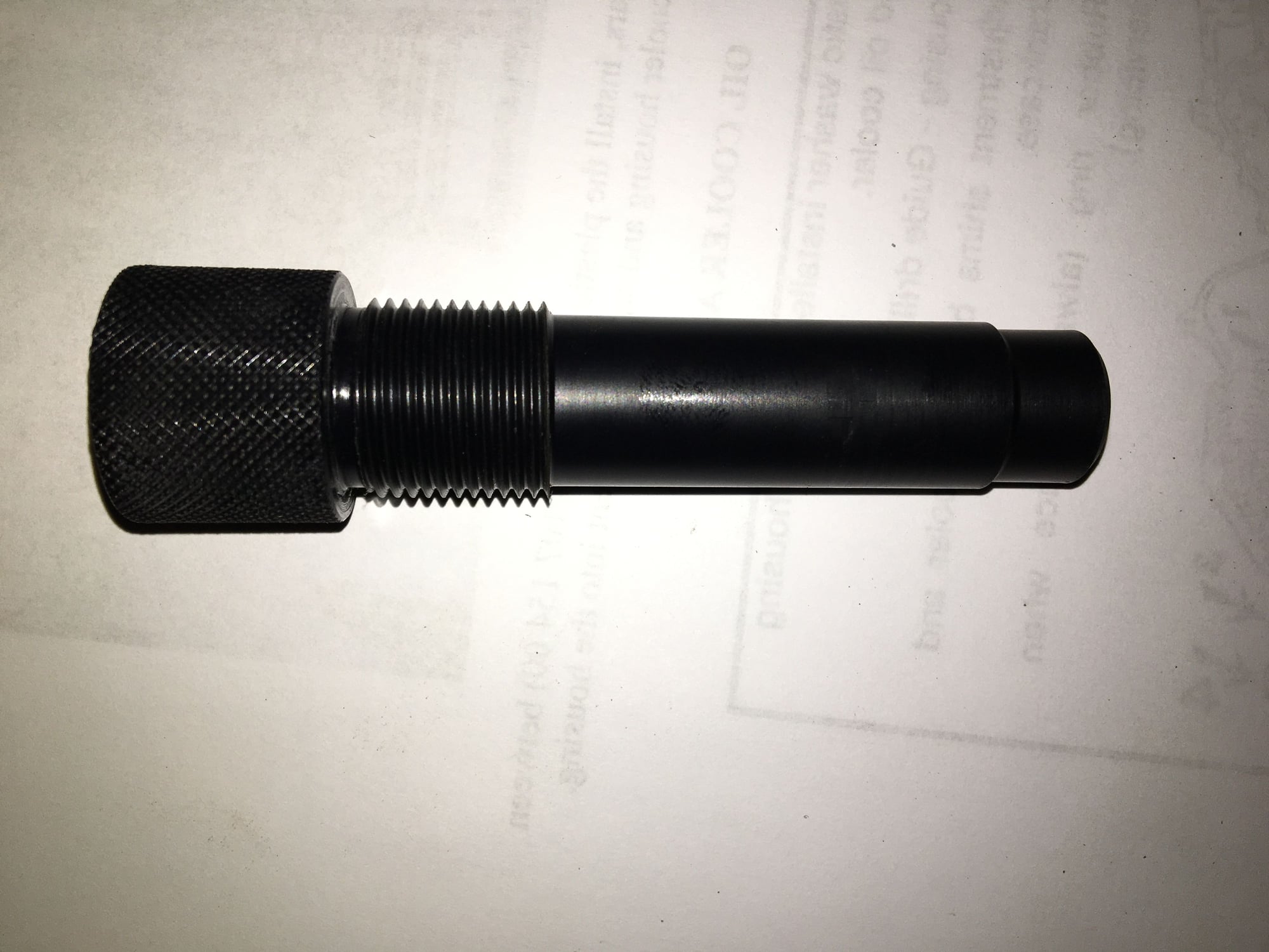
One discovery I made was the availability of an OPRV alignment tool made from polyurethane that was less than half the cost of the original steel item. Here is a link to an eBay posting for the same unit & seller:
The unit seems to be very precise and as far as I can tell, worked perfectly. A lot of people say the chances are good that OK results will be had using the actual OPRV as an alignment tool, but I feel better going this route...
EDIT: All the pictures are rotated and cropped by the forum... I don't know why this is happening or how I can correct it. If I get enlightened I will re-attach the images. Sorry for how they look right now (you can't see everything you should...)
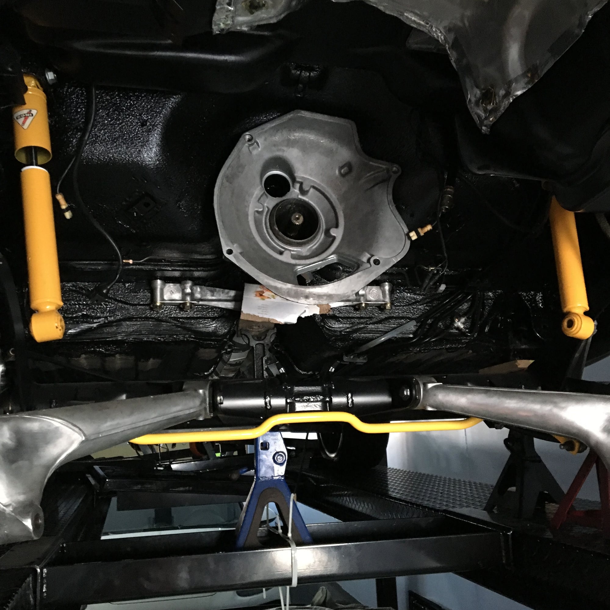
In between the slow assembly of the engine, I re-rebuilt the torque tube...
I had previously rebuilt the TT by replacing the bearings in the standard bearing carriers.
Subsequently, I became aware of the very nice SuperBearings produced by Black Sea R&D and really wanted to have these.
Unfortunately, by the time I found out about these, the TT was back in the car and this means I had to drop the rear suspension etc. to remove the TT.
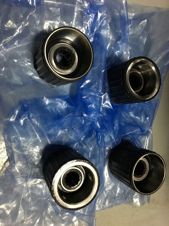
These are the four SuperBearings. They are VERY substantial!
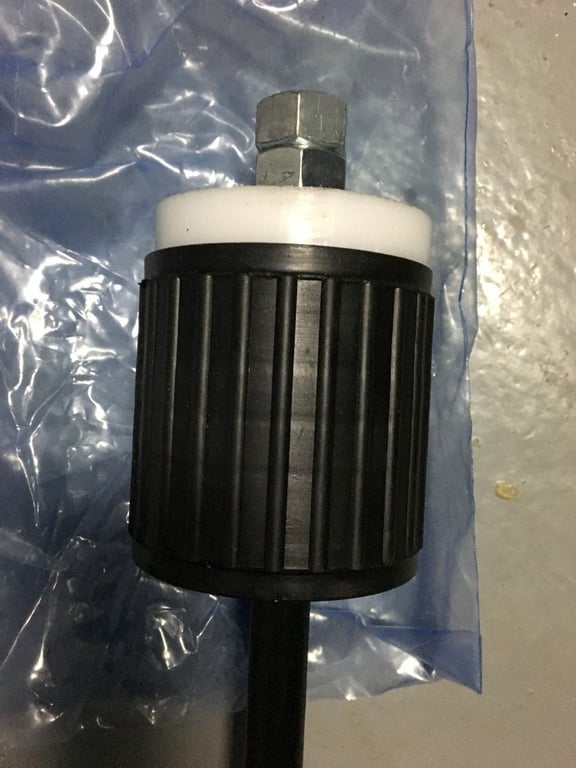
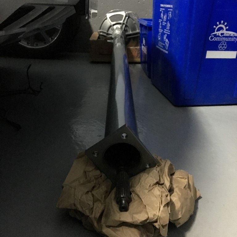
A sized Delrin disc is used in conjunction with threaded rod/nuts/washers to pull the bearing units into position. The disc came with the bearings, as did a clear lubricant that was used for the shaft installation.
Black Sea provides detailed installation instructions and the install was trouble free, although the endless turning of the nut on the threaded rod to get the bearing units into position was tedious!
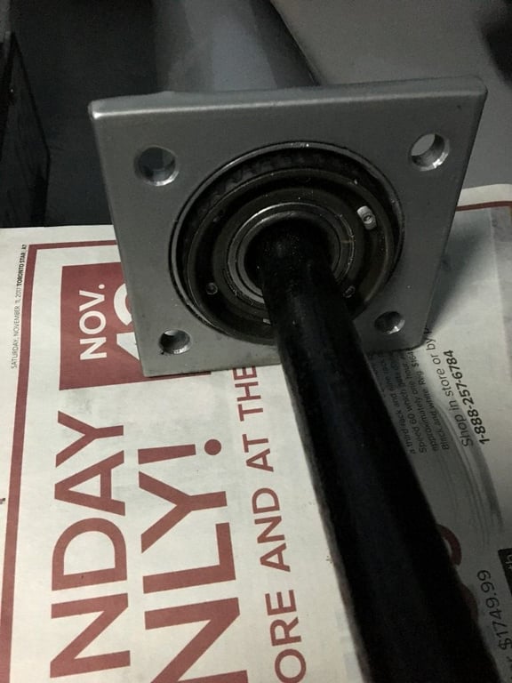
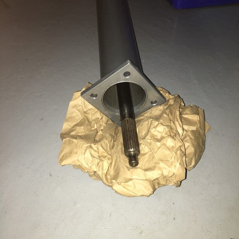
The shaft slid in smoothly, but required a pretty firm pressure. I had painted the shaft with a thin coat and used liberal amounts of the supplied lubricant, which must have helped quite a bit. The photo below shows one of the original bearing carriers that was positioned loosely at the front end of the TT to act as a positioning aid when sliding the shaft (the plastic center bushing was first removed and the bearing carrier was taken out once the shaft was installed).
Everything feels good, so I expect no problems from this part of the car! The first time I rebuilt the TT I had it powder coated, so it looks pretty nice for something that will be invisible!
Lots of scattered progress lately, but the very cold weather we have had over the past couple of weeks has also had an impact.I have the re-rebuilt TT back into the car, but I have yet to reinstall the rear suspension sub assembly. I first will be changing the spring plate bushings. I originally put in Elephant Racing polybronze units the first time I assembled this, but with yet another change of heart, I decided I would prefer OEM-style rubber (which is what I did on the 911 project). Once I have the polybronze units out, I will see if I can sell them on here, as they have exactly zero miles on them!
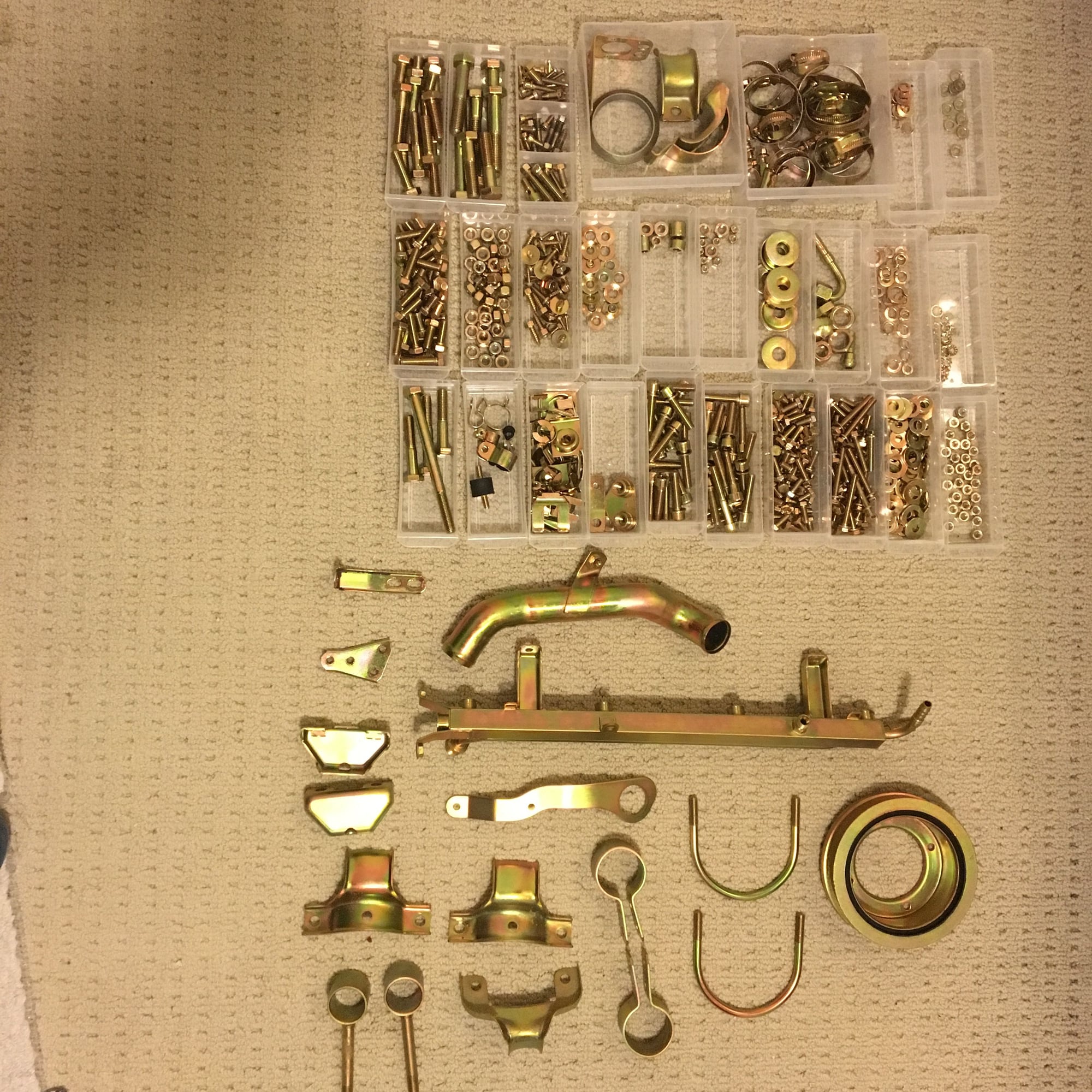
Another item that has taken up time in getting a batch of parts re-plated (yellow zinc dichromate). This is the third batch for this project. It is a bit of a laborious task as I individually itemize each part in a spreadsheet. This batch was composed of 715 parts… this is what it all looks like now:
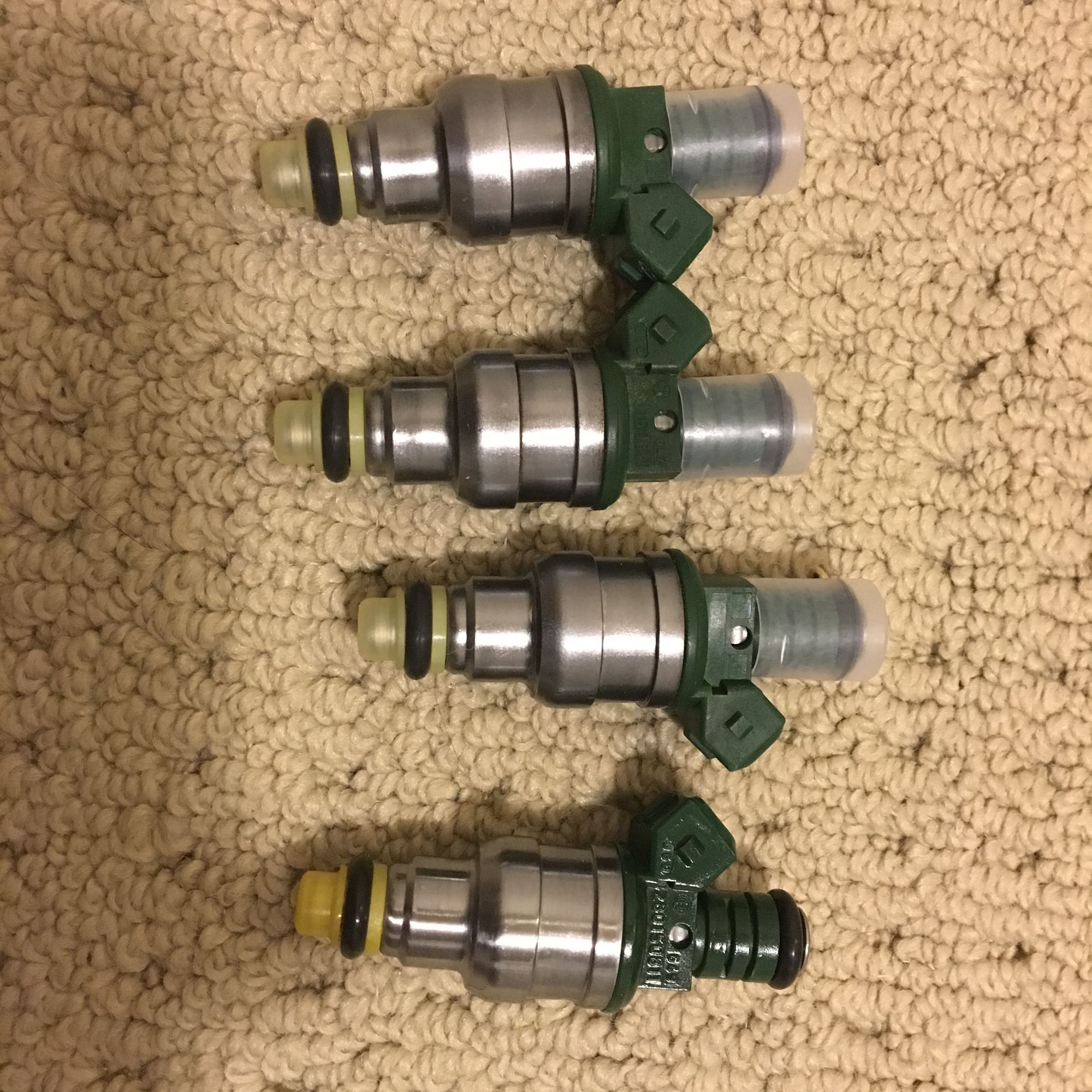
I am getting ready to put the intake together, and needed to have the injectors reconditioned. Three of them turned out excellent, but one was found to have a small leak in the body, so I had to source a replacement. Fortunately I found a good one and I now have a very good, matched set ready to go…
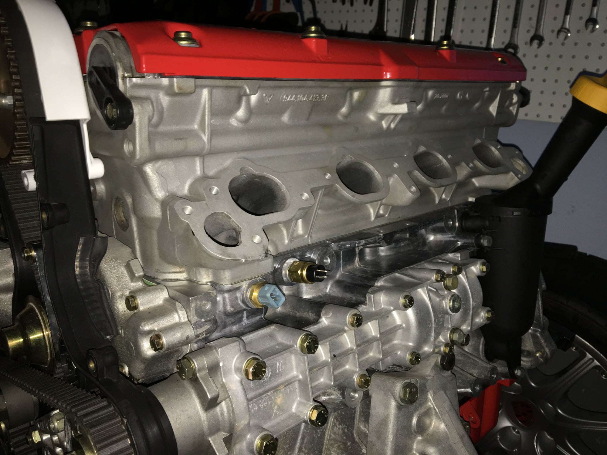
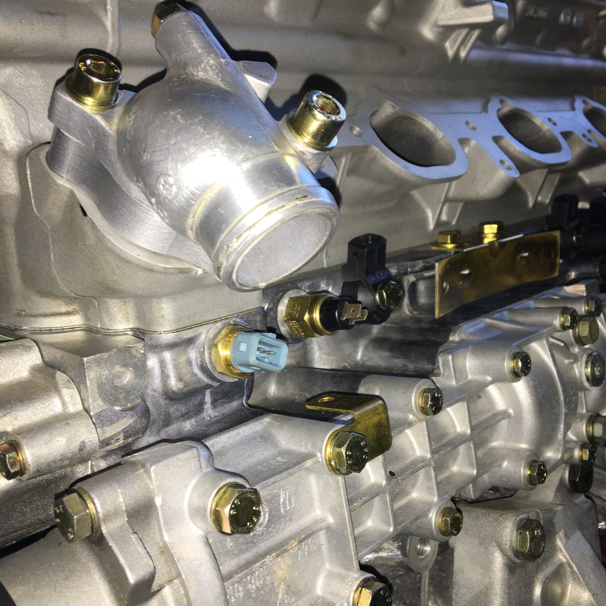
First I had to arrange the new temperature and knock sensors on the driver’s side of the block, and add in the aluminum coolant inlet/outlet housings, as well as some hardware for supporting the wiring harness:
Some years ago, when I was in the early stages of this project, I was concerned about the condition of the original DME harness. At the time, the 1987 944S harness was NLA, but the 1988 was… The key difference for 1988 was the addition of an intake manifold heating valve (situated on the intake manifold just after the throttle body). Thus, the ’88 S harness has the extra connector for that. All the same, I spent time checking the harness against the wiring diagram to verify that I had correctly identified each connector.
There is an excellent thread on here about making your own harness, and given that the connectors are all available, this may be a better option. As it is, I am going to have three unused connectors: The aforementioned manifold heating valve, the power steering pump switch (I am putting in a new manual steering rack and deleting the PS) and the oil level warning (my sump does not have the sender for oil level warning). That last one is interesting. When I took the car apart, I did not realize that was what that connector on the old harness was for (it wasn’t plugged into anything). Since then, my “research” has shown that this oil sender was something that Porsche added to the 944 series in 1987, but my car apparently has an “old style” sump without the facility for the sender. This is interesting to me, as it would suggest that the sump was changed out in the car’s life, which I would not expect, as there is no record of significant work… If anyone knows more detail about when this sender was actually implemented, it would be interesting to know…
Anyway, back to the car… I needed to connect the harness to the sensors on the block prior to the intake manifold, as it looked to be really tight to do it after. Everything is as original, including new, blue “omega” clips!
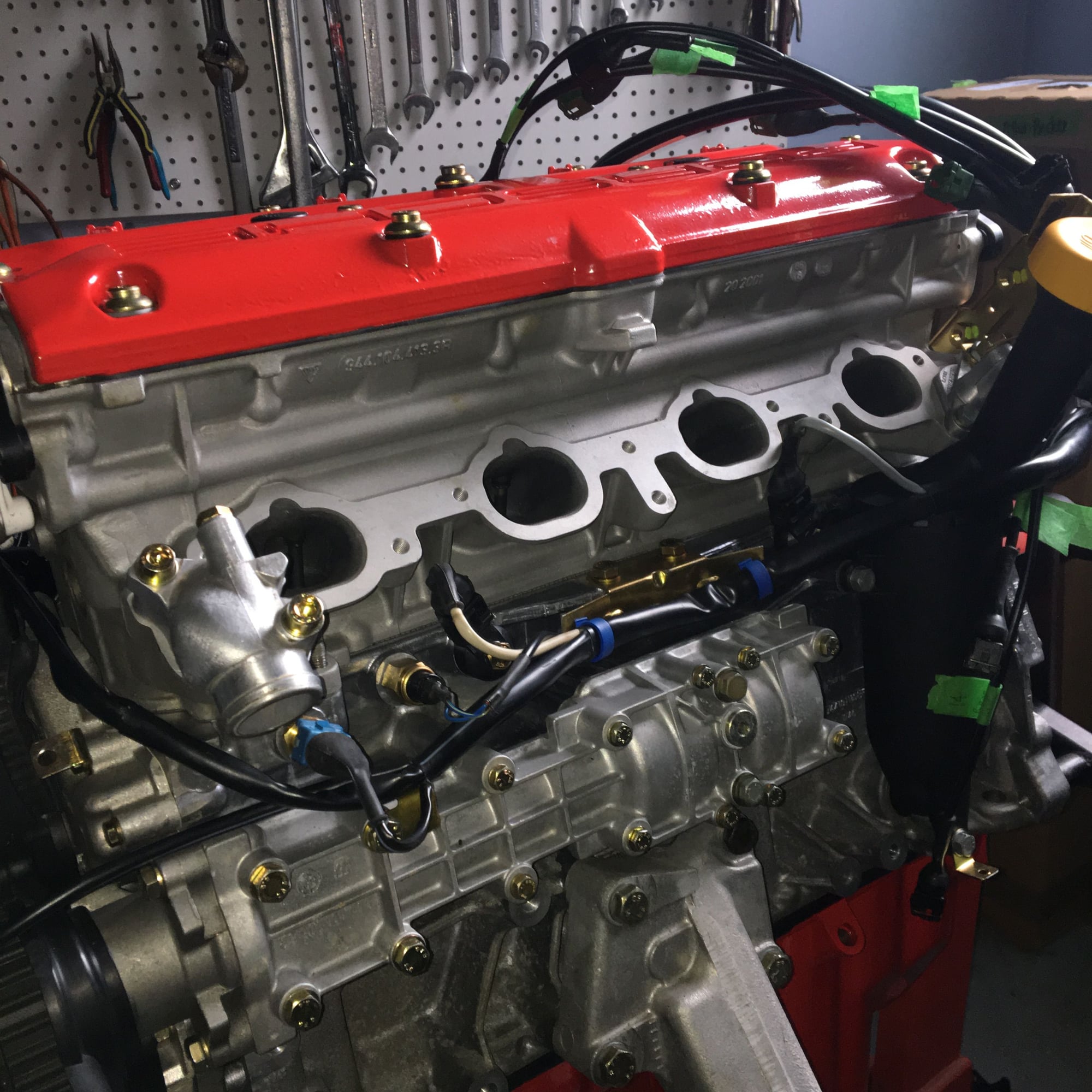
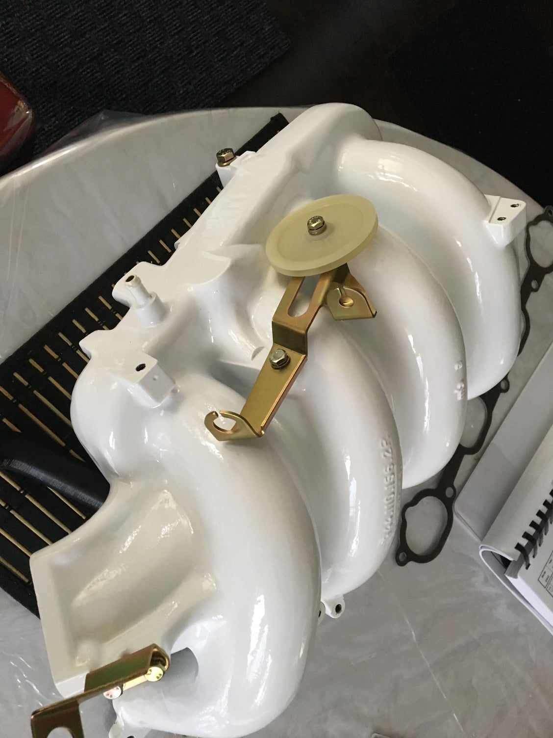
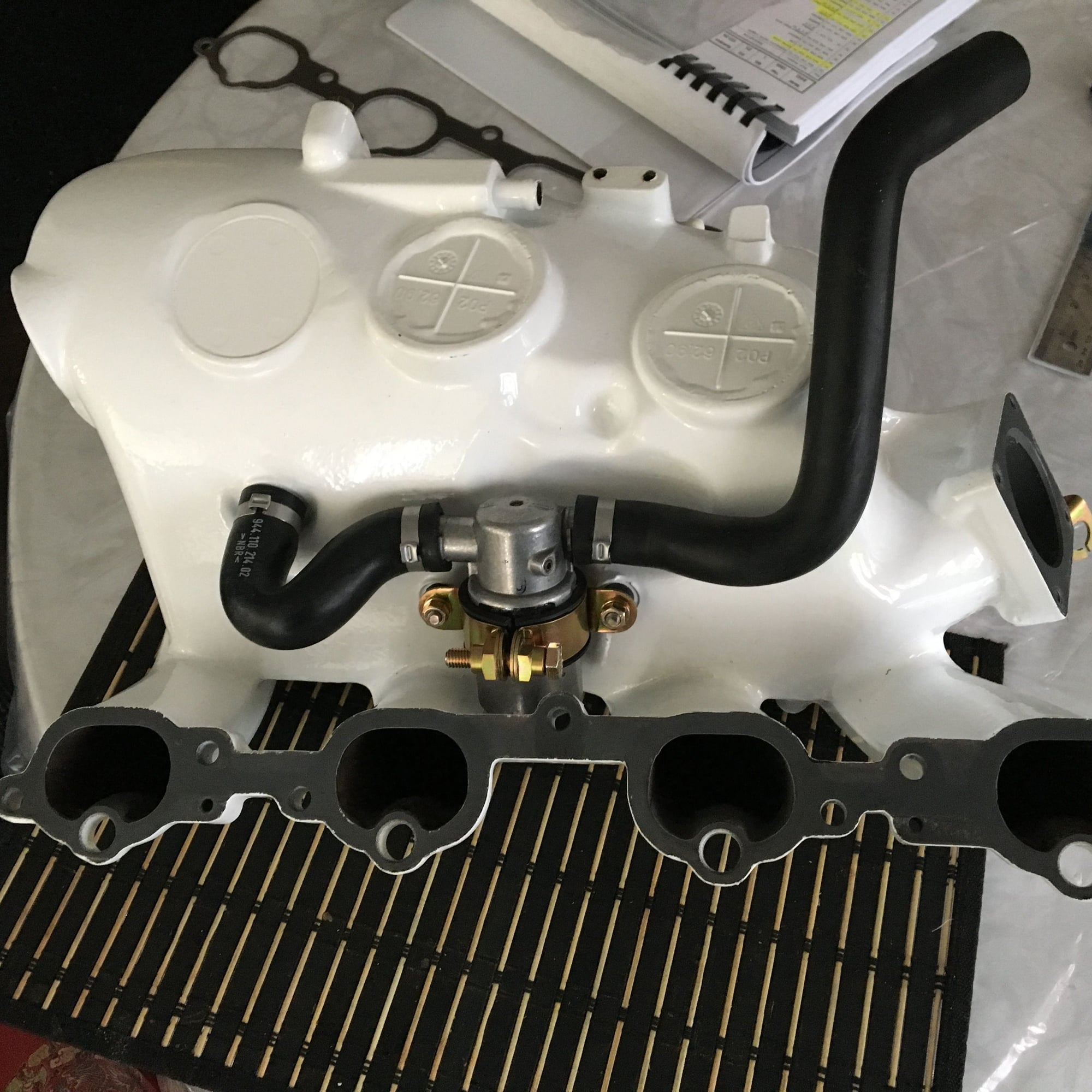
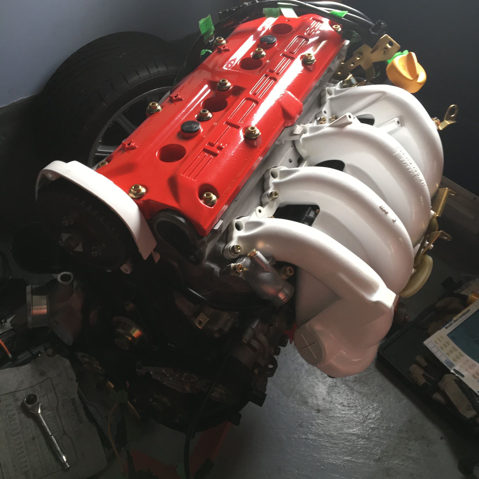
For the intake manifold, I decided on white powder coat as a nice contrast to the red cam cover. I pre-assembled the various re-plated hardware bits.
I clamped on the new hoses for the idle stabilizer valve. I am doing the typical venture delete (which is actually what the normal active Porsche part numbers for these hoses specify):
With the intake manifold on, the engine is starting to look complete, even though there is still quite a lot to do!
Interesting about the oil pan.. My 88S had the sender, but the interesting part is that the inside had been semi polished at the factory, it was not as cast like my 968 pan.

 06-30-2017, 11:17 AM