When you click on links to various merchants on this site and make a purchase, this can result in this site earning a commission. Affiliate programs and affiliations include, but are not limited to, the eBay Partner Network.
I need to admit a massive error here....Was on the phone with Michael today for several hour discussing why my resolution was so much worse in my tuning tables, and yet the car ran perfect for over a yeart! He, being the smarter engineer between us, informed me of a massive oversight I made in my initial wiring. I am running 12 ohm injectors, but in addition I ALSO am running a 7.5 ohm, 25 watt resistor on each injector channel. What that means is that each injector driver, instead of seeing a 6 ohm load, was actually seeing a 13.5 ohm load......which means that my injectors were getting only about 5.5 Vdc and NOT the 12.5 my alternator puts out! That would MASSIVELY slow down the opening of the injectors and explains why I had to run them at a VE of nearly 90 to idle the car with 83 lb injectors vs the ~40ish or so that it should require. Suddenly its all crystal clear.....
Cheers everyone, watch your resistance's when doing your wiring. Triple check everything. In my case, no harm done except I'll need to retune my car when I finally get it running again!
My Fueling would have been off by ~55% if my injectors were seeing 6 ohms and not 13.5 ohms and were therefore getting the correct voltage. I had to readjust everything in my map to compensate for the fact that I will be removing the resistors entirely. I also decreased reqfuel by about 15%. The new map should run the car just as well as the previous maps or better, but give me about 50% better resolution on fuel related data fields. Many thanks again to Michael. Here is the new, but not yet fine tuned msq file.
I really appreciate all the info you guys are sharing here. I'm planning on a Megasquirt conversion on my S soon, most likely next year.
I had planned on going all the way for sequential injection since the S is already equipped with a cam sensor, so I'm watching this discussion with interest.
Talking with Doug over the phone reminded me of a topic I wanted to bring up in my last post but forgot: injector dead time (aka: injector opening time). It's self descriptive, and is usually between 0.5-1.5 ms. You can hopefully find the dead time for your injectors online or from a data sheet. Make sure you also look at what voltage that value is given for, MS has a setting for that.
Megasquirt (and any other real ECU) looks at that number to determine how far in advance to initiate the injector opening, to allow for the correct firing time of the injectors. So let's say at a given point in time, the injector needs to deliver 5 ms of fuel. Hypothetically let's say your dead time is 1.00 ms. Therefore, MS provide the injector with 6 ms of voltage (well really it provides a ground but you get the picture).
You can also see the detriment of having the injector dead time incorrectly set. If the actual dead time at 13v is 0.85 ms and you tell MS that it's 1.15 ms, you're always going to be injecting 0.30 ms of fuel more than you should be. The result is an artificially low VE table, because you have to adjust that to compensate for the extra fuel. The opposite phenomenon is true if your dead time is set too low.
It gets really important when you have big injectors. If you think about it, the time that the injectors have to stay open is quite small when the injectors are quite large. Before we used an example of 5 ms required, but let's say for larger injectors, it's 2.6 ms. If the injector dead time is 0.85 ms, that's almost 1/3 as much as the required injection time! So if it's off, the impact is MUCH larger on the actual fuel being delivered.
Another consideration is the time between injector firings.
Batch fire
In this mode, each injector fires once per cycle. So the time between firings is 720 degrees.
Sequential injection
In this mode, each injector fires once per cycle. So the time between firings is 720 degrees.
Semi-sequential injection
In this mode, each injector fires twice per cycle. So the time between firings is 360 degrees. The actual time that injector needs to fire is cut in half: each half fires during each crank rotation and resets every complete cycle. Because there are two distinct firings, there are 2 opening times.
So for semi-sequential, getting the dead time set correctly is absolutely critical, because at high RPMs you have a much narrower window to inject all the fuel at the correct opening time.
I have to admit that I have no idea what my correct opening time is; I can't the spec anywhere. I'm looking into measuring the dead time using experimental tests and will update with my findings if anyone is interested.
Adding on to what Michael said, RE: Injection timing. With Batch fire, none of the pulses are "on time" except arbitrarily perhaps at a single specific RPM when it just so happens to line up properly. Even then, it would only be for a specific cylinder.
On an even fire inline 4, each cylinder is always 180* out of phase so the effect is that with untimed injection; one cylinder is getting its fuel sprayed onto the closed intake valve on the exhaust stroke, one is getting it sprayed onto the intake valve on the compression stroke, one is getting is sprayed onto the valve on the power stroke, and one is getting is sprayed onto/into the valve on the intake stroke.
which cylinder gets its fuel on which stroke is called "phasing" and once the engine is started, will not change as long as the engine remains running. How the cylinders are phased upon start is a random consequence of the position of the 4 pistons in the bore relative to TDC intake stroke.
Running in Semi-sequential, it is still only "partially timed" in the sense that with a properly set up injection timing table, you are still only getting fuel injected "on time" (~10 degrees before the opening of the intake valve) half of the time. The other half of the fuel is injected 360* out of phase, sprayed onto the intake valve at the beginning of the exhaust stroke.
Again, with respect to phasing, this is a somewhat random consequence of which piston is where in it's bore in terms of deciding which two cylinders get their fuel on time and which two get it 360* out of phase but because the engine must complete two rotations to complete one cycle, the phasing with respect to which cylinders get their fuel on time and which don't is constantly changing as the engine completes cycles.
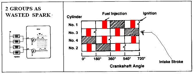
The below image helps visualize what I am talking about with respect to batch fire. You can see all 4 injectors fire at the same time, once per 720* of rotation and that only 1 cylinder is even close to getting its fuel on time.
This diamgram shows timing for semi sequential. You can see how its essentially timed semi batch fire, the injectors are still fired in pairs. Two cylinders are getting their fuel on time, while two are getting their fuel 360* out of phase (within each 720* engine cycle).
I have a set of 1000 cc Hi-Z injectors from smartfireinjectors.com.($55 bucks each)
I scanned the document they send with their injectors for finding the injector dwell time.
Thanks for that, first time I've heard of that sort of procedure to measure dead time. I find it odd though that the company specifically states that its vital to getting good AFR's during engine braking....if your car is set up properly, your injectors should be off while engine braking and AFR's should be off the chart lean, just the way our cars (and almost all cars) run from the factory.
Careful with those 100 lb injectors. If you run them in semi sequential on gasoline, you're "req_fuel" will be in the range of ~2.2 ms and your idle PW in the range of ~.9 to 1.00ms. With a dead time (dead time tends to increase somewhat linearly with respect to flow) for those 100 lbers probably approaching 1ms, you can see how that could be an issue at idle/low loads! If PW drops below the point at which the injector is stable, the actual amount of fuel injected can become very erratic. The length of PW that marks this point of instability gets larger with bigger injectors.
This sort of more clearly demonstrates the short coming of large injectors that many guys have simply heard parroted, which is that it can be hard to get large injectors to idle well. One solution is to run them in batch fire, which will double the pulsewidth everywhere, or run E85 which will force the PW to be ~30-35% longer!
For your scrutiny, here are my numbers with 875cc high Z injectors on both gas and E85: My injectors have a manufacturer specc'ed .885ms dead time @ 13.2Vdc and my tune includes a correction factor (+.110ms/volt) to compensate for the slower opening if voltage drops below that.
Gas: 5.0ms "req_fuel", 2.19ms idle pulse width in batch fire mode.
E85: 7.2ms "req_fuel", 2.93ms idle pulse width in batch fire mode.
You can half those idle PW's if I run the car in semi sequential. For me, my car does not idle well in semi sequential, reason being that my injector's have a minimum stable PW of 1.95ms before going into the "non linear knee" and an absolute minimum operating PW of 1.7ms. It idles perfect in batch fire.
(FWIW, the max linear PW for my injectors is 8.2ms and an absolute operating max of 9.8ms, but they are delivering more than 500 rwhp worth of fuel at that point!)
One more note which really doesnt apply even to 100 lb injectors; but for those guys running 3.0 liter cars that need HUGE amounts of fuel and are running 120-160lb injectors, the only way to get them to idle often times, even in batch fire, is to simply raise the idle speed to force the idle PW up into the injector's stable range. This is one reason among several others why race engines often have high idles.
Taking my blunder as a good learning example, the math says that according to my correction factor, with my injectors getting a nominal 5.5Vdc supply, MS was adding a dead time correction factor of .770ms on top of the specc'ed .962ms @ 12.5Vdc! It's very obvious now why that inflated my VE numbers so much, since my ACTUAL dead time was on the order of 1.732ms but MS was expecting it to be only .962ms!
azbanks, thanks for the scan. I want to try that technique out. I know you and Doug have heard of this, but for everyone else, here's a cool idea...
If you can't get a good idle with big injectors, you can stage some bike injectors (or otherwise small injectors). This requires a custom manifold, you would 8 injectors total. The bike injectors would idle the engine, and they would transition to the large injectors as PW increased. It's all doable and programmable in MS.
Anywho, just took the NA out for a long tuning run. I have a really solid semi sequential tune nailed down, and will post it once I finish dialing in acceleration enrichment.
I am planning on going to full sequential with my system. I may pick up a set of smaller injectors if these ones cause any issues. With a 16 valve 3 liter running a GT3582R turbo, I'm thinking I can use big injectors.
Eric I think you'll be on the ragged edge with those injectors but you could get away with it, if you idle it a little rich and at higher RPM than you normally would (maybe 1200 rpm? although see how it runs at a lower speed). I'm calculating a req_fuel of 5 ms for those injectors.
MS calculates the injector pulse width with this equation:
PW = REQ_FUEL * VE * MAP * E + accel + Injector_open_time
("E" is the sum of all enrichments, "accel" is the acceleration enrichment, and Injector_open_time is the dead time.) To be conservative, simplify that to this form (E = 1 and accel = 0), to model the lowest PW that will be sent in an idle situation:
PW = REQ_FUEL * VE * MAP + Injector_open_time
In addition to the 5 ms figure I'll use the following assumptions: dead time = 0.67 (13v as per your scan), VE = 50 (appr. where I idle) and MAP = 35 kPa (again based on where I have solid idle). Baro = 103 kPa, adjust as needed. 3 bar fuel pressure assumed.
That yields:
PW = 5 * (50/100) * (35/103) + 0.67 = ~1.52 ms
Note that out of that figure, almost half is due to the dead time (opening time), so you're really fortunate to have that figure on hand.
This is going to be the section covering setting up flex fuel. It isnt as hard as it sounds, and it really adds a nice layer of usability and.....flexibility to turbo cars running E85.
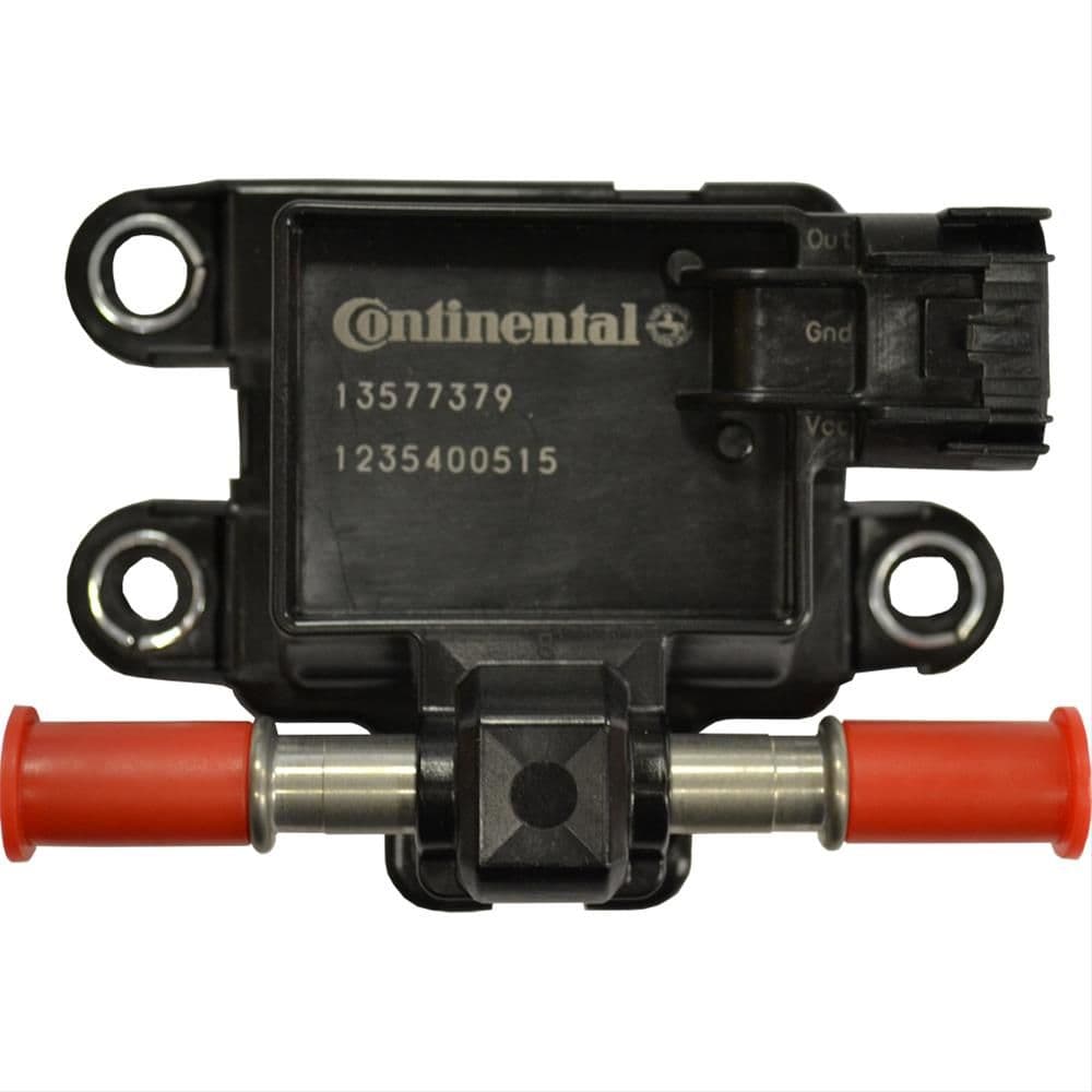
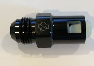
For starters what you'll need is one of these
That's a standard GM flex fuel sensor found on every modern GM vehicle. The biggest issue is they use GM quick-disconnect fittings, so you'll need to be clever to splice that into your lower pressure fuel return line somewhere near the rail. MS has an input specifically for interfacing with a flex fuel sensor, and tables built in that allow fine tuning.
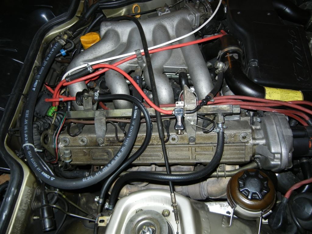
The best way to splice the sensor in is going to be to find some Stainless steel GM fuel line fittings which have a barb on the output side, and then double clamp an ethanol safe length of fuel line between the barb and the barb on the fuel rail using high pressure fuel injection rated clamps at both ends. I recommend Gates Barricade fuel injection hose, its rated to several hundred PSI and is ethanol rated. Available at O-Riellys.
like this
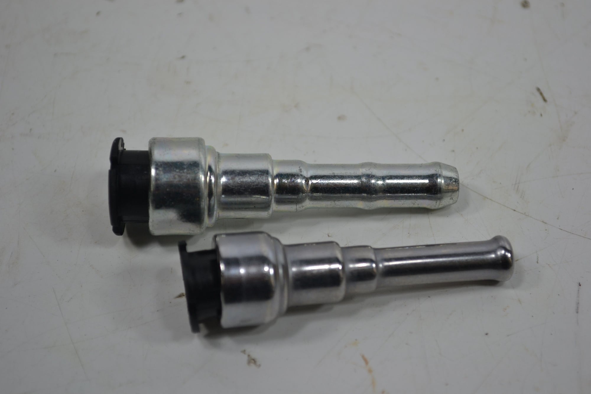
And these are the type of GM fittings you'll need
They also have these fittings if you have AN stainless braided fuel lines that will interface with standard 3/8" GM quick disconnects
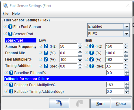
The low and high frequency values correlate to 0% and 100% ethanol mix respectively. They are a function of the frequency the sensor puts out, but MS is already setup to use GM sensors so if that is what you are using leave those values alone.
Keep in mind pump fuel is actually 10% ethanol, so you'll need to adjust that in the baseline ethanol field. Set the failsafes super rich so that if you ARE running E85 and the sensor fails, you'll still get enough fuel. Worst case scenario is that it fails while you are running pump gas and it goes so rich the car wont run, but thats better than a blown engine and those sensors are VERY reliable.
Under the multiplier fields, on the low side leave the fuel at 100% and the timing at zero if you tuned the car originally on pump fuel. This tells MS to use the standard tune when running pure pump gas. leave the high side fuel at ~160% though you may need to turn this down some if it runs too rich with lots of E85 vs pump in the mix. Remember that stoichiometric for E10 pump fuel is 14.1:1 but 9.7:1 for E85 and around 8.3:1 for pure Ethanol. That means you'll need ~35-40% more fuel on E85 vs E10 pump. E85 likes more timing, so the 3.5+ degrees will add 3.5* of timing EVERYWHERE on your timing map. that's probably sufficient, you might even be able to get away with more since our motors like lots of timing due to their large bores and relatively poor fuel atomization/swirl; which its self is a function of our cylinder head design.
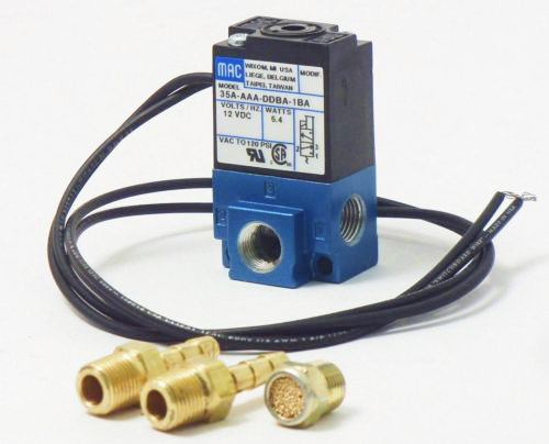
You've come this far. Take that nice spinny-thingy manual boost controller or the fancy standalone electronic boost control ECU and put em on Ebay. MS can control boost electronically with a build in input and function table. For starters, you're going to need an electronic boost solenoid like this one >>>
That gets plumbed in the standard way a boost controller gets plumbed, which I wont cover here. It gets wired into the Fidle pin (though you can use other inputs if Fidle is being used for something else) and one side gets grounded. There isnt much to say here other than to play with the settings until it responds the way you want and holds your target boost level. The required settings will depend on your motor, your wastegate, your turbo, and your exhaust to a small extent.
In that table there is also integrated overboost control which will automatically cut ignition if boost rises above a preset limit. This is a nice safety feature and should definitely be implemented. MS can set variable boost limits based on % ethanol with flex fuel enabled, letting you have more maximum boost the more E85 is in your tank; another really nice feature that lets you have both safety and the ability to fully enjoy benefits of E85.
Under the separate "boost control target" table you can also set target boost levels by rpm which can limit boost below a certain rpm threshhold, while at the same time allowing quicker spoolup than you'd get with a MBC or a non-integrated EBC.
Did you know MS has integrated knock control? It's true, is has basically the same functionality as the factory KLR, except with finer control and a much higher sampling rate. For NA cars, it adds functionality that the car never originally had.
For starters, go check this site out http://www.viatrack.ca/
since they sell the MS knock box you'll need to implement knock control with MS. You'll want to reuse the factory knock sensor, NA cars will need to drill the boss where the 951 unit is placed on the head and install and wire up a factory sensor.
You'll need to provide viatrack with some info on the car since each MS knock unit is custom tuned to the particular engine it is going on.
Here is the knock sensing table
The MSknock box will feed the binary "yes/no" knock signal into the MS via your choice of a multitude of spare input pins.
You'll want to set the "knock ignored above MAP" setting to over 105 kpa for an NA car and over your maximum boost on a boosted car. Other wise MS might miss knock counts at high boost, which would defeat the purpose.
You can also set the rpm window to ignore knock counts below a certain rpm, say 3500 rpm for a boosted car since below that you will not get more than 100 kpa in the manifold.
It's worth noting that the knock senseing/timing retard function is MS can operate in two modes, "safe" mode and "aggressive" mode. The data fields are all fairly self explanatory here, the retarding section describes the maximum amount of timing MS can pull out, how often it will check for knock and continue to pull timing if still detected, and the amount of timing pulled out each time is makes a correction when it detects knock. The advance section describes how the ECU recovers back to normal timing after knock is no longer detected.
In general this system works MUCH better than the factory KLR, I encourage everyone to invest in a MS knock unit and set up this functionality.
This, along with the overboost protection described in an earlier post essentially eliminates the possibility of a non-mechanically related engine failure or engine damage and makes the tune way safer than any motronic based tune.
Doug touched on a cool feature of MS in these last few posts: the spare wires, and how you can use them for other functions outside of simply reading sensors or running injectors/coils. So here's all you need to know about
Programmable on/off outputs
So as you can see, you can control things like boost using onboard settings. To add on to that, you can control almost anything electronic with a little imagination.
As the name suggests, these are just for activating/deactivating devices. Basically, you give MS some parameters (which are based on inputs) and it will turn something on or off. You can control electric cooling fans, a nitrous shot, control a shift light with respect to load and RPM, shoot confetti from a modified airbag, change compressor bypass with respect to vehicle speed or any other measurable variable, the list goes on and on.
It's pretty easy to set up. All you do is go to the menu for it, and choose the spare output wire you want to use. Then, choose the default state: that will either be on or off. Next, you choose the conditions under which the state will change. You can utilize any of the measured inputs (there are dozens... RPM, MAP, coolant temp, etc) or a calculated output, which MS calculated based on the sensor inputs or curves you've already set up.
You can even use logical operators like AND/OR, so it will consider multiple inputs. For example, a shift light that activates when RPM > 4500 and MAP < 80 kPa.
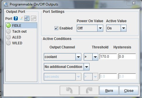
Here's how my cooling fans are configured:
You can see I'm using the Fidle pin, and it's by default off, but will be switched to on ("active value") when the condition below is met. That condition looks at the coolant, and when it is above 170 deg. F (you can choose unit system in settings) it will activate.
So what actually activates? It's simple, MS grounds whatever wire you selected (in my case, Fidle). That's perfect for controlling a relay - you provide one side of the activation stage switched +12v and hook the other side to the MS controlled spare output. Then, you wire up your device to get power from the relay and you're done. For fan control, I'm simply using the relay as a replacement for the fan switch. It works exactly as intended and I can change the activation temperature as I please, as seasons change and etc.
You can control practically anything in this fashion, even things that aren't EFI related as you can see.

 12-04-2015, 03:53 AM