
Mini-project: tightening up shift linkage
 05-23-2012, 09:55 PM
#1
Rainman
Rennlist Member
Rennlist Member
Thread Starter
Hi all,
Just sharing with you a few things I am working on right now to try to tighten up the feel of the 944 shifting mechanism. I "fixed" the stock pin and that was a significant improvement over the worn egg-shaped shifter pin but the rest of the system has play as well.
Last time (2 years ago, maybe more) what I did was grind down the welds on the shift lever and remove the pin. I drilled the pinhole out to 7/16 on the shift lever and also the hole in the shifter rod it goes into. Cut a piece of 7/16 rod to length and welded it on, and tapped the end of the rod for a small screw/washer to hold it all together. There is still some play though at the lever end, I imagine the hole is wearing again.
So I've decided to go through and tighten up everything. Most of this is based off of what I have seen other people do before here on RL, such as user SoCal924 and robstah, so I cannot claim credit for the ideas. However, if you are interested in doing something similar, this could serve as a guide for you.
All parts needed can be found at McMaster-Carr.com, along with many local hardware stores like ACE or Lowe's.
Part I: Shift lever/shifter rod slop
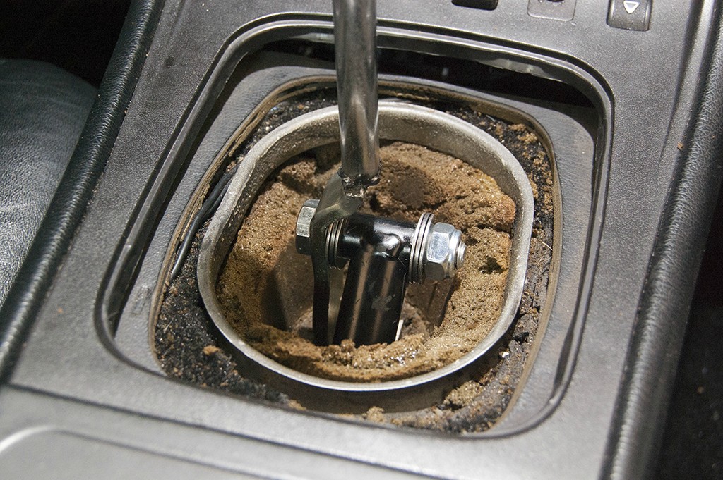
I am going to copy what robstah did recently, but removing the pin from the shift lever and installing a M10x50 bolt/nut in the hole through the shifter rod, with needle roller bearings and appropriate washers in between. What this does is take the wear/movement action off of the shifter rod hole itself and puts it on the side edges of the rod. The bearings should make it very smooth in operation, and there should be basically no play whatsoever once it's all bolted together.
I have not done this yet, but will post pictures when I get around to it maybe this weekend. For now, you can see his thread for explanation/pictures.
(https://rennlist.com/forums/924-931-...pool-ball.html)
Parts needed:
- M10x50mm bolt- x1
- M10 nylon lock nut matching the bolt above - x1
- M10 thrust bearings - x2 (McMaster 5909K11)
- M10 thrust bearing washers - x4 (McMaster 5909K71)

Part II: Transmission-end linkage pivot
The stock linkage is a bent piece of stamped steel, with balljoints and plastic inserts and rubber grommets to give it enough wiggle room to pivot around. However, the plastic inserts wear and the rubber gives too much wiggle when it dries out and collapses a bit. So my solution, based off of Socal924's solution years ago, was to replace it with new ball bearing joints.
Parts needed:
- M8x1.25x110 both-end-threaded stud - x1 (M-C 93275A034)
- M8x1.25 regular nuts - x2
- Ball-joint linkage with M8x1.25 threaded ball-stud, right-hand thread (M-C 6058K821) - x2
Put them together like so and adjust until the length is correct (should be around 145mm bolt to bolt).
Just sharing with you a few things I am working on right now to try to tighten up the feel of the 944 shifting mechanism. I "fixed" the stock pin and that was a significant improvement over the worn egg-shaped shifter pin but the rest of the system has play as well.
Last time (2 years ago, maybe more) what I did was grind down the welds on the shift lever and remove the pin. I drilled the pinhole out to 7/16 on the shift lever and also the hole in the shifter rod it goes into. Cut a piece of 7/16 rod to length and welded it on, and tapped the end of the rod for a small screw/washer to hold it all together. There is still some play though at the lever end, I imagine the hole is wearing again.
So I've decided to go through and tighten up everything. Most of this is based off of what I have seen other people do before here on RL, such as user SoCal924 and robstah, so I cannot claim credit for the ideas. However, if you are interested in doing something similar, this could serve as a guide for you.
All parts needed can be found at McMaster-Carr.com, along with many local hardware stores like ACE or Lowe's.
Part I: Shift lever/shifter rod slop
I am going to copy what robstah did recently, but removing the pin from the shift lever and installing a M10x50 bolt/nut in the hole through the shifter rod, with needle roller bearings and appropriate washers in between. What this does is take the wear/movement action off of the shifter rod hole itself and puts it on the side edges of the rod. The bearings should make it very smooth in operation, and there should be basically no play whatsoever once it's all bolted together.
I have not done this yet, but will post pictures when I get around to it maybe this weekend. For now, you can see his thread for explanation/pictures.
(https://rennlist.com/forums/924-931-...pool-ball.html)
Parts needed:
- M10x50mm bolt- x1
- M10 nylon lock nut matching the bolt above - x1
- M10 thrust bearings - x2 (McMaster 5909K11)
- M10 thrust bearing washers - x4 (McMaster 5909K71)
Part II: Transmission-end linkage pivot
The stock linkage is a bent piece of stamped steel, with balljoints and plastic inserts and rubber grommets to give it enough wiggle room to pivot around. However, the plastic inserts wear and the rubber gives too much wiggle when it dries out and collapses a bit. So my solution, based off of Socal924's solution years ago, was to replace it with new ball bearing joints.
Parts needed:
- M8x1.25x110 both-end-threaded stud - x1 (M-C 93275A034)
- M8x1.25 regular nuts - x2
- Ball-joint linkage with M8x1.25 threaded ball-stud, right-hand thread (M-C 6058K821) - x2
Put them together like so and adjust until the length is correct (should be around 145mm bolt to bolt).
 05-23-2012, 09:56 PM
#2
Rainman
Rennlist Member
Rennlist Member
Thread Starter
Part III: Transmission-end plastic bushing
This bushing joins the fore/aft and side/side movement of the transmission linkage with its plastic body and rubber grommets. However after 25 years of shifting the holes inside the bushing have worn out slightly and the rubber is crushed, giving a small amount of wiggle-play.
There is a vendor out there that sells a billet aluminum replacement, but attempts to contact him have been unsuccessful and prices are not listed on his site. It would be not too difficult to make that product but as I don't have reliable access to a machine shop I am going to try to modify it to use some sort of bearing (perhaps the thrust bearings listed above) to take away the play and the wear point. Have not done this yet, will keep posted.

Trending Topics
05-24-2012, 01:10 PM
#8
Rainman
Rennlist Member
Rennlist Member
Thread Starter
Also, I am considering just drilling the black shifter rod all the way through for a bolt/nut combination instead of the odd factory pointy-end bolt that holds it all together.
05-24-2012, 04:12 PM
#9
Race Car
Just doing my shifter too. I replaced the shift lever, and that was a huge improvement, but the shifter rod is slightly worn as well. I have parts in hand and will drill the shifter rod to 12mm and install a hardened steel bushing 10mm ID, and 12mmOD. This sleeve will be replaceable and should hold up better than the shift rod steel, M-C has similar sized bronze bushings that should work too.
I will then look at the rear with consideration of your aforementioned mods. Thanks.
Side question, I am also going to attempt to make my own front swaybar mount(inner) supports similar to the KLA versions. Anybody have plans or measurments to go by? This should be easy with a piece of flat steel stock, no?
05-24-2012, 04:15 PM
#10
Rennlist Member
the shift lever on my 944 is new, however the shifter rod has wallowed out causing a TON of slop. i pan on using robstah's plan to fix that issue. will prob buy a faulty used shifter seeing as mine is new. V2Rocket_aka944 keep us updated on how everything pans out for you!!
05-24-2012, 04:32 PM
#11
Rainman
Rennlist Member
Rennlist Member
Thread Starter
Just doing my shifter too. I replaced the shift lever, and that was a huge improvement, but the shifter rod is slightly worn as well. I have parts in hand and will drill the shifter rod to 12mm and install a hardened steel bushing 10mm ID, and 12mmOD. This sleeve will be replaceable and should hold up better than the shift rod steel, M-C has similar sized bronze bushings that should work too.
I will then look at the rear with consideration of your aforementioned mods. Thanks.
Side question, I am also going to attempt to make my own front swaybar mount(inner) supports similar to the KLA versions. Anybody have plans or measurments to go by? This should be easy with a piece of flat steel stock, no?
I will then look at the rear with consideration of your aforementioned mods. Thanks.
Side question, I am also going to attempt to make my own front swaybar mount(inner) supports similar to the KLA versions. Anybody have plans or measurments to go by? This should be easy with a piece of flat steel stock, no?
 06-04-2012, 08:49 PM
#12
Racer
Do the thrust bearing and its two washers that are added to the driver's side of the shift rod cause the shift lever to tilt to the driver's side a little?
Is it enough to be noticeable or annoying?
[QUOTE=V2Rocket_aka944;9556172]
Is it enough to be noticeable or annoying?
[QUOTE=V2Rocket_aka944;9556172]
06-04-2012, 10:39 PM
#13
Rainman
Rennlist Member
Rennlist Member
Thread Starter
The bearings wouldn't change the tilt that is already there, likely due to the orientation of the trans-end linkage.
By the way, got my bearings installed yesterday - feels NICE.
By the way, got my bearings installed yesterday - feels NICE.
06-05-2012, 03:22 PM
#15
Rainman
Rennlist Member
Rennlist Member
Thread Starter
Angle grinder makes quick work out of the original weld on the shift lever - maybe 30 seconds of grinding down. Once you see the full circle of the end of the pin in the ground-down weld, a punch and sledge hammer knock it out easily. Make sure to grind the weld fairly flat so that the bolt rests evenly.