Inside the cooling fan relay
 10-04-2004, 03:58 PM
#1
Rennlist Member
Thread Starter
I knew my coolant system wasn't operating correctly. At highway speeds it would run at the first white line. But then when sitting in traffic, it would slowly climb, and keep climbing until it got to just under the red line. Then the fans would kick in at high speed and bring the temp back down to the second white line. It always made me nervous getting close to the red so I decided to investigate.
Thinking it was the thermofan switch, I followed the Clark's garage procedure in diagnosing the problem. When connecting pins two and three of the thermofan connector, it's supposed to turn on the fans in slow speed. Nothing happened. I turned on the ignition and pressed the AC button. This is supposed to turn the fans on in slow speed. Again, nothing happened. So everything is pointing to the cooling fan relay. It still could be that the slow speed resistors were burned out, so I pulled the relay and applied 12V to the V1 and V2 terminals. Both fans turned on in slow speed. So it's definitely the fan relay.
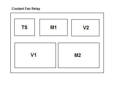
After looking up the price of this relay (around $130), and being the cheap bastard that I am, I decided to try to fix the relay myself. The inside contains five relays and some diodes and resistors. Here's the general layout of the components. None of the components were labeled on the board so I took the liberty of naming them after the signals they control. The TS relay controls the V1 and V2 relays.
Nothing appeared to be wrong with any of the components. No burnt contacts on the relays. No stuck relays. No burnt resistor or diodes. So I traced all the wirings and came up with the schematic below.
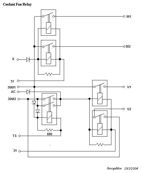
Here's a description of the signals
X - ignition -- on=12V off=0V
TF - temp fast -- on=0V off=float
TS - temp slow -- on=0V off=float
AC - air cond -- on=12V off=0V
31 - ground
30M1 - fused 12V
30M2 - fused 12V
M1 - cooling fan 1 high speed
M2 - cooling fan 2 high speed
V1 - cooling fan 1 low speed
V2 - cooling fan 2 low speed
Here's how to test it without actually opening it up. I used a battery charger for the 12v supply and numerous alligator clips and jumpers. Apply 12v to terminals 30M1 and 30M2. Apply ground to 31.
1) Ground TS. Terminals V1 and V2 should go to 12V indicating slow speed fans. Remove ground on TS. V1 and V2 should go to 0V.
2) Apply 12V to AC. Terminals V1 and V2 should go to 12V indicating slow speed fans. Remove AC. V1 and V2 should go to 0V.
3) Ground TF. Terminals M1 and M2 should be at 0V. Apply 12V to X. Now M1 and M2 should go to 12V indicating high speed fans. Notice that M1 and M2 don't go to 12V until the ignition (X) is turned on.
Mine failed test 1 and 2 indicating that it could be relay TS which controls the V1 and V2 relays. But it turned out that I had a rare double fault. My V1 and V2 relays weren't working. When I looked closer, I could see my V2 relay trying to activate, but all it would do was buzz. The coil actually shifted on the core and was physically preventing the relay from closing. So I pushed it back to its original location. My V1 relay has a broken coil and can't be fixed without replacing it. So at least one of my fans will operate in the slow speed now. If test 3 fails, then it's either your M1 or M2 relays that is bad.
If you take the cover off to see what's inside, you can also apply 12V across the coil of each relay so find out the bad one. If all the relays are good, then it will be one of the diodes or resistors.
I don't know how much this will help anyone since it's hard to repair anything on this relay board unless you have a spare around that you can rob parts from. And it's probably not worth the time, but here it is in case your curious. This component is pretty straight forward in operation and not as complicated as it first looks.
So I put my "fixed" relay back into the car and went for a ride. Now when idling, the temperature goes up to the second white line and the one fan (should be two) comes on at slow speed. At least the temp doesn't go above this second white line and stays away from the red. Nervousness averted and $130 saved.
Thinking it was the thermofan switch, I followed the Clark's garage procedure in diagnosing the problem. When connecting pins two and three of the thermofan connector, it's supposed to turn on the fans in slow speed. Nothing happened. I turned on the ignition and pressed the AC button. This is supposed to turn the fans on in slow speed. Again, nothing happened. So everything is pointing to the cooling fan relay. It still could be that the slow speed resistors were burned out, so I pulled the relay and applied 12V to the V1 and V2 terminals. Both fans turned on in slow speed. So it's definitely the fan relay.
After looking up the price of this relay (around $130), and being the cheap bastard that I am, I decided to try to fix the relay myself. The inside contains five relays and some diodes and resistors. Here's the general layout of the components. None of the components were labeled on the board so I took the liberty of naming them after the signals they control. The TS relay controls the V1 and V2 relays.
Nothing appeared to be wrong with any of the components. No burnt contacts on the relays. No stuck relays. No burnt resistor or diodes. So I traced all the wirings and came up with the schematic below.
Here's a description of the signals
X - ignition -- on=12V off=0V
TF - temp fast -- on=0V off=float
TS - temp slow -- on=0V off=float
AC - air cond -- on=12V off=0V
31 - ground
30M1 - fused 12V
30M2 - fused 12V
M1 - cooling fan 1 high speed
M2 - cooling fan 2 high speed
V1 - cooling fan 1 low speed
V2 - cooling fan 2 low speed
Here's how to test it without actually opening it up. I used a battery charger for the 12v supply and numerous alligator clips and jumpers. Apply 12v to terminals 30M1 and 30M2. Apply ground to 31.
1) Ground TS. Terminals V1 and V2 should go to 12V indicating slow speed fans. Remove ground on TS. V1 and V2 should go to 0V.
2) Apply 12V to AC. Terminals V1 and V2 should go to 12V indicating slow speed fans. Remove AC. V1 and V2 should go to 0V.
3) Ground TF. Terminals M1 and M2 should be at 0V. Apply 12V to X. Now M1 and M2 should go to 12V indicating high speed fans. Notice that M1 and M2 don't go to 12V until the ignition (X) is turned on.
Mine failed test 1 and 2 indicating that it could be relay TS which controls the V1 and V2 relays. But it turned out that I had a rare double fault. My V1 and V2 relays weren't working. When I looked closer, I could see my V2 relay trying to activate, but all it would do was buzz. The coil actually shifted on the core and was physically preventing the relay from closing. So I pushed it back to its original location. My V1 relay has a broken coil and can't be fixed without replacing it. So at least one of my fans will operate in the slow speed now. If test 3 fails, then it's either your M1 or M2 relays that is bad.
If you take the cover off to see what's inside, you can also apply 12V across the coil of each relay so find out the bad one. If all the relays are good, then it will be one of the diodes or resistors.
I don't know how much this will help anyone since it's hard to repair anything on this relay board unless you have a spare around that you can rob parts from. And it's probably not worth the time, but here it is in case your curious. This component is pretty straight forward in operation and not as complicated as it first looks.
So I put my "fixed" relay back into the car and went for a ride. Now when idling, the temperature goes up to the second white line and the one fan (should be two) comes on at slow speed. At least the temp doesn't go above this second white line and stays away from the red. Nervousness averted and $130 saved.

The following users liked this post:
Tach (09-29-2021)
10-04-2004, 04:10 PM
#2
Pro
Join Date: Oct 2001
Location: Chester, NH
Posts: 551
Likes: 0
Received 0 Likes
on
0 Posts
I too followed the Clark's garage test and the relay failed. My car acts similar to yours (running hot), but I spent the $176 at the Porsche dealer for the new relay thinking "great, at least I'll be able to drive it". Wrong the new one works or fails the same test. I will try some of the things/tests that you mention but I'm pretty dim, married with children and can only get my P-car fix here while "working".
10-05-2004, 01:53 PM
#4
Got Nothin'
Rennlist Member
Rennlist Member
If you are interested, I have instructions on how to eliminate that relay and replace with relays bought at an autoparts store and some diodes from Radio Shack. Total cost is time plus maybe 20 dollars.
I did this on my car, and it works like a champ. All functionality of the relay at 1/5 cost.
I did this on my car, and it works like a champ. All functionality of the relay at 1/5 cost.
10-05-2004, 02:11 PM
#5
Rennlist Member
Thread Starter
Yeah PeteL, I would be interested. Does it still use mechanical relays?
I was thinking of designing one myself using solid state relays to make it more reliable. Ditto for the DME relay.
I was thinking of designing one myself using solid state relays to make it more reliable. Ditto for the DME relay.
10-06-2004, 01:30 PM
#6
Got Nothin'
Rennlist Member
Rennlist Member
The relays are mechanical. I used 30A relays from Autozone. Now I have some sweet 40A waterproof relays that I got from IceShark a few months ago. I will email the directions when I get home tonight.

Trending Topics
10-06-2004, 11:45 PM
#8
Got Nothin'
Rennlist Member
Rennlist Member
Here are the instructions, I have used them successfully:
1. You need two 20 or 30 amp automotive relays. www.kuncow.com has Bosch with hangers for $2.50 each, a real bargain. I started out with both fans on the same relay. This meant that both fans came on together every time. Two problems. This creates a large surge and resulting "shock" to the electrical system which while manageable can't be the best thing. Second, I found the cooling system cyled a bit too much ... that is the fans came on, knocked the water temp down pronto, then had to come back on. On, off, on, off. This is eliminated by putting each fan on it's own relay.
2. Decide if you want to just hang the relays from something or put them in a project box/plastic enclosure. Radio Shack has neat boxes, $5. Use the plastic, not metal lid.
3. Decide where you want to put the relays/box. It is much easier to locate them under the hood as you don't have to fish wires through the firewall. In deciding where, realize you have to run some pretty good size wires from the fan motors to the box, and from the box to either the a) battery, b) alternator, or c) starter. I use a cone filter so I put my box behind the driver's headlight, just in front of the reservoir, over the hole the factory snorkel used. I also run my feed cable to the large post on the starter which made it easy to hide.
4. Once you decide on a location, disconnect your battery and run your feed cable or wires. I had a medium sized cable made to fit for $5 at a battery shop. Lugged on one end to fit the starter post, coupled to 2 6" 12 AWG wires on the other since wires are easier to run into a box than a cable and you need to split the cable anyway to tie into two relays. If you don't want a cable, run two wires.
5. Fuses. I fused my lines in the box which means my cable running to the starter is unprotected and could start a fire if it grounds. Same as the factory but it is up to you. Either way, you need to fuse this feed line on one end or the other. In line, weather resistant 30 amp holders with a 30 amp fuse are $1.50 at AutoZone. NAPA has nicer ones but they cost more. You need two plus a smaller one, like those used on radios, see later.
6. Feed line, safely ensconsed in split loom or radiator hose, to box. Fuses wired in. Relays bolted in box. The two feed wires, after the fuses, connect to Terminals 87.
7. Now ground Terminals 86 to the chassis or battery. One ground wire is sufficient but it must be branched to both Terminals 86. It should be a good size, if not 12 AWG, then 14 AWG. For more on sizing wire, see the chart and write up at http://www.susquehanna.com/susq/other/wiring.htm. I grounded mine at the chassis ground located just behind the driver's headlight.
8. Run good sized wires from Terminals 30 to the fans. Doesn't matter which side of the fan motor. Do keep track of which relay is connected to whch fan, labeling the relays Fan #1 and Fan #2. If you want to keep your factory harness intact, you can pull off the factory connector, tie it out of the way, and use a standard wire connector. Alternatively, you can buy a used or new factory connector and use it.
9. Run new ground wires from the other side of the fans to a chassis ground. Again, I used the one immediately behind the driver's headlight.
10. Now you have a working relay. 12v will be fed from the battery directly to your fans whenever the relays are switched on. Cool. Tough part is getting those relays to come on when you want them to
11. Terminals 85 of the relays do this. (You don't use the middle terminal. Cover it in shrink wrap to protect it and forget it). We need to run three wires to each of these Terminals 85 and it gets a bit complicated.
12. First, go to an electronics store and buy 6 diodes. Not flashing diodes but standard diodes, they look like little tiny barrels with a band painted on one end. All six should cost you $2. You need the ones with a 6 in the part number. I can't find my file tonight but I think they are 00n6 or something like that. The 6 is the important number, the guy will know what you mean. 7's will work just as well.
13. Take a standard female electrical wire connector ( I like the G&B brand from Home Depot better than the ones int the auto parts places) and strip off the insulator. Solder three diodes to the wire end, barrel of the diode pointed towards the connector. Now solder three male connectors to the diodes, one each. Now, do it all again so you have two of these contraptions. Plug the female ends of each contraption to Terminal 85.
14. Take the connector off your radiator fan switch. Here, again, you might wish to get a used one if you wish to leave your factory harness intact. There are three wires coming out of the plug. The factory set up is such that the fan switch provides a ground for the fans ... the fans being hot all the time but not able to run until the fan switch provides a ground. We are going to change that because, to make a long story short, we have to, to make the A/C connection later on. A spare, working, radiator fan switch will also help when it comes to testing.
15. Your connector should have a yellow/brown, a red/white, and a brown wire. Looking directly into the connector, with the notch up, the brown should be on the right, the red/white on the left. Connect the red/white to one of those three male spades which leads to a diode. on Fan #2 relay. Connect the yellow/brown to one of the male spades ON THE OTHER RELAY, Fan #1. Connect the brown wire not to a relay but a fused, 12v power source. Even though I said not to connect it to a relay, that's what I did, simply using a piggy back spade connector and a small in-line fuse to one of the Terminals 87. Now you have automatically switched relays. The 12v runs into the fan switch. When it closes at 180 degrees, it passes 12v back to Fan Relay #1 and it, in turn, switches on Fan #1. Same for Fan Relay #2 when the Fan #1 can't keep the heat down and the temp rises to 190 degrees. Note that the car does not have to be running ... if the water is 180 or higher, the fan or fans will run. The diodes keep the signal from the A/C switch (below) from running through the relay and back into the fan switch circuitry.
16. Now, for the A/C. Find the factory cable that originally fed the fans. Trace it back about two inches from where it branched out to feed both fans. Connect your battery and turn on the key, no need to start the car. Hit your snowflake button. The fans shouldn't run because the factory harness is disconnected. Open the sheath, again, about 2 inches before it branches out, and find the one wire that goes hot when the snowflake button is on. I think it is red and brown or red and black but I can't remember. I will find out for sure and email you but that is the wire you want. Make sure it is not one that is hot every time the key is on, you want the one that is hot only when the key is on and the A/C switch is on. Splice onto it and run a wire to the relays where you want to branch it and connect the two branches to two more of those male spades leading to diodes, one per relay.
17. Okay, now you have 12v to both the relays when the snowflake button is pressed. Just like the factory, if the A/C is on, both fans are on. Period. The diodes keep any current from the relays or the fan switch from getting back into your expensive climate control switch.
18. Finally, you have two male spades left on those diodes. Run short jumpers from each to Terminals 86. This is a spark supression trick that will eliminate any interference the relays might cause to your stereo.
19. If you have a spare radiator fan switch, and I hope you do, plug it into the connector and let it hang down below the radiator. Take a propane torch and heat it. Fan #1 should come on first. Fan #2 next. Remove the torch. Fan #2 should go off in a minute or two, followed in another minute by Fan #1. Turn on the key, hit the snowflake button, both fans should run. Button it up, carefull securing and protecting all your wiring in split loom, it's cheap and easy to use. Secure it with tie wraps.
20. Three notes:
a) Thanks to Martin Taylor for his help in all of this. He is a true gentleman.
b) Call me at 704 668 7019 if you need a hand. Please don't share this number.
c) This procedure eliminates the half speed feature used by the factory.
Finally, I've sent a copy of this to Martin. If he is back from his vacation, he can check my work. Either way, you should proceed cautiously and test these connections as you go. Work with the battery disconnected and install the fuses. That way, the worse that can happen is that it won't work when you turn it on in which case we'll figure out where my instructions went awry and change the connections so it does work.
Finally, finally. It isn't as bad as it sounds but it is time consuming. Since your factory harness has been screwed, you will want to make sure that your snowflake button is still sending a hot signal to the fans. Other than that, you should be good to go with what you have but if not, and this set up doesn't work, we'll figure that out as well.
10-07-2004, 01:41 PM
#9
Rennlist Member
Thread Starter
Hey PeteL,
Let's see if I can summarize what you did. You have one relay controlling each fan. When the 92C is reached, you turn on one fan. When 102C is reached, you turn on both fans. If the A/C button is pressed you turn on both fans no matter what. You always turn on the fans in high speed.
Although this will work and is simpler, I don't like this design for a couple of reasons.
1) You have to basically replicate all the wiring to the fans. I don't think many on this board would be open to this. All the wiring is already in place. I was thinking of designing a direct replacement of the relay that plugs into the same slot.
2) It still uses mechanical relays, although yours are much cheaper to replace.
3) There's no redundancy. If one relay goes out, you lose the ability to cool your engine.
4) The fans always run in high speed. This is just a noise issue.
I'll have to see if I can get motivated enough to come up with a solid state design that plugs into the same slot.
10-07-2004, 04:01 PM
#10
Addict
Rennlist Member
Rennlist Member
Other option is gutting the relay, and soldering wires onto its base connectors, so you get to use all the stock wiring and relocate your extra relay box elsewhere, like right next to the main fuse box...
10-07-2004, 08:57 PM
#11
Got Nothin'
Rennlist Member
Rennlist Member
Originally Posted by StoogeMoe
Hey PeteL,
Let's see if I can summarize what you did. You have one relay controlling each fan. When the 92C is reached, you turn on one fan. When 102C is reached, you turn on both fans. If the A/C button is pressed you turn on both fans no matter what. You always turn on the fans in high speed.
Although this will work and is simpler, I don't like this design for a couple of reasons.
1) You have to basically replicate all the wiring to the fans. I don't think many on this board would be open to this. All the wiring is already in place. I was thinking of designing a direct replacement of the relay that plugs into the same slot.
2) It still uses mechanical relays, although yours are much cheaper to replace.
3) There's no redundancy. If one relay goes out, you lose the ability to cool your engine.
4) The fans always run in high speed. This is just a noise issue.
I'll have to see if I can get motivated enough to come up with a solid state design that plugs into the same slot.
Let's see if I can summarize what you did. You have one relay controlling each fan. When the 92C is reached, you turn on one fan. When 102C is reached, you turn on both fans. If the A/C button is pressed you turn on both fans no matter what. You always turn on the fans in high speed.
Although this will work and is simpler, I don't like this design for a couple of reasons.
1) You have to basically replicate all the wiring to the fans. I don't think many on this board would be open to this. All the wiring is already in place. I was thinking of designing a direct replacement of the relay that plugs into the same slot.
2) It still uses mechanical relays, although yours are much cheaper to replace.
3) There's no redundancy. If one relay goes out, you lose the ability to cool your engine.
4) The fans always run in high speed. This is just a noise issue.
I'll have to see if I can get motivated enough to come up with a solid state design that plugs into the same slot.
2) Very true.
3) Perhaps, but even with one bad relay, with the A/C on, the other fan works.
I live in a hot climate and almost always run the A/C.
4) Yes, but with my climates, more cooling is better.
11-26-2017, 05:33 PM
#12
Rennlist Member
Hello all,
I apologize for dredging up such an old post. I am very new to the Porsche world, having recently purchased a 1986 944 with 160,xxx miles. As you might have guessed, I am having cooling issues. After having re-bled the system, I am confident that there is no air in the system. The cooling system works great while the car is moving, just like the thousands of other posts I have read. I believe the issue lies in the cooling fan control system somewhere.
I have already gone through the Clark's test procedure for the fan relay. The relay failed step #6 where both fans were supposed to run at high speed when plug positions 1-3 were jumped, and with the ignition switch on. All the other operational test steps passed.
Then I decided to use the procedure in this post as an in depth check of the relay. I removed the cover to check for the obvious like burned contacts, etc. Everything looks good in there. All the tests per Moe's procedure passed. The only thing that may be slightly suspect is the voltage did not drop completely to ZERO, after the applied voltage or ground was removed. Positions V1, V2, M1, M2 continued to have a residual voltage of .02 to .04 volts. I assume this is probably OK, but don't really know that it is. Confirmation of this would be appreciated.
In addition to these tests, I have removed the fan resistors and checked them out. Resistance between positions V1 and M1 as well as V2 and M2 at the fan relay sockets measures 1.4 ohms, which I understand is in spec. The fan resistor wiring looked pretty good, compared to some of the scary looking pictures I have seen. I cleaned up the contacts on the pucks and reinstalled the pack. I am not too sure about the microswitches, as one of the studs pulled out of the back to the switch and I had to JB Weld it back together, much to my chagrin. Hopefully this is not too big a deal.
I would appreciate the time and effort of a person that has experienced this specific problem and how they might have overcome it.
Thank you,
Doug Vazquez
Shelton, WA
The following users liked this post:
Sasquatch 2001 (01-23-2020)
11-26-2017, 08:28 PM
#13
Rennlist Member
Thread Starter
You really don’t describe the problem you’re having. Are you saying that when idling in traffic that the temperature will climb up to the red?
If your slow speed fans are working, that is usually enough to keep it cool, unless it is really hot outside. If it still is getting hot, then check your bleeding or debris in the radiator. What line does it run at on the gauge on the highway?
If you tested the relay and it passes but still won’t turn on the fans in high speed when you jumper the pins at the switch, then you’re not getting voltage to the X pin at the relay when the ignition is switched on. Or you have wiring problems between the thermostat switch and relay, or relay to the fans.
11-26-2017, 09:00 PM
#14
Rennlist Member
Thanks for getting back to me, I really appreciate it.
Yes, idling while not moving, the temperature will climb to the red. While moving it stays consistently near the first white mark, maybe slightly above it, whether I am going 70 or 30 or even less. The problem seems to be that the fans do not turn on consistently. I cleaned up all the ground points on the car to eliminate that as source of the problem. I have pressure bled the system twice and am confident the system is adequately bled. I believe the physical part of the cooling system (thermostat, radiator, hoses, etc) is operating as it should, though I guess anything could be goofy on a 32 year old car.
After posting earlier today, I double checked the front ground points, the fan relay and the fan resistors. While checking the resistors, I noticed that the M2 connection slot did not seem as positive (tight) as the M1, V1 and V2 positions, so I slightly bent the M2 blade on the relay. This position controls the driver side fan, which did not turn on when I checked it last night and this morning.
Then I double checked the Clark procedure, jumping the temperature switch connections. This time, all the operational steps of the procedure checked out OK, slow speed, with key off and key on, high speed with key on, and low speed with key on and AC switch on. Both fans ran as they should on all steps of the procedure. Bending the M2 relay blade may have corrected the earlier failure of the Clark procedure step 6 for the #2 fan to come on at high speed with the key on.
Since all this now checks out OK, it seems like maybe the temperature switch might be the next check. I am guessing it needs to come out to test it. Is this the case, or is there an electrical test of some sort that can be performed in place?
Thank you,
11-26-2017, 09:31 PM
#15
Rennlist Member
Thread Starter
Well if it works now by jumping at the switch, and it still overheats, then it’s the thermo switch that is faulty. Not that expensive, but somewhat painful to replace.