When you click on links to various merchants on this site and make a purchase, this can result in this site earning a commission. Affiliate programs and affiliations include, but are not limited to, the eBay Partner Network.
My idea for using the FIDLE output was this, curious to hear your opinion:
- Middle pin gets 12v
- One outer pin gets chassis ground, however, there is a resistor in series.
- Other outer pin goes to a TIP120 transistor
That transistor is pulsed by FIDLE to pass a ground to the 3rd pin. That way, one side of the ICV is always active (hardwired to ground). But, when FIDLE indirectly pulses the other side, it overcomes this because of the resistor inline with that hardwired ground. So instead of trying to control both sides, you can just control 1 side and the closed loop algorithm should be able to figure it out.
My idea for using the FIDLE output was this, curious to hear your opinion:
- Middle pin gets 12v
- One outer pin gets chassis ground, however, there is a resistor in series.
- Other outer pin goes to a TIP120 transistor
A few thoughts...
1) You don't need the transistor if you're using a Microsquirt. The Microsquirt Hardware Manual states that the max current for the FIDLE output is 3A. My measurement of the coil resistance is about 12 ohms, which puts the max current at around 1A. (I pretty much confirmed this value by the Amps readout on my bench power supply). So the MS should be capable of driving a single coil by itself.
2) Other people appear to have had success hard-wiring one of the coils to ground through a resistor, even though this isn't how Bosch did it. But you need to use an appropriate wattage resistor, since it could be dissipating a fair amount of power depending on the value. The question then is where to put this resistor. If you put it inside the DME, then all that heat is getting trapped inside the case, which is not ideal. If you don't put it inside, then you've got to find some place to splice it into your harness, with all the hassle that entails. The value of the MOSFET driver circuit I'm using is that it has very low on resistance, meaning that most of the energy is dissipated by the coil itself, which is conveniently located in the engine bay with all the other hot things.
3) I suspect that the resistor approach reduces the effective resolution of control, because a certain amount of the ICV PWM range is taken up overcoming the force from the always-on coil. Effectively, the lower the resistor value, the more of the PWM range gets eaten up. This may not be a problem in practice, though.
4) I think you'd want to be sure to place the resistor on the close coil, not the open coil. Otherwise the MS would have to constantly drive the close coil under normal running conditions just to keep the valve closed.
5) My belief (unconfirmed) is that either circuit should work in closed-loop mode, with the caveat that, if the resolution of control is reduced too much (by having too small a resistor), the algorithm will have a hard time keeping the idle steady.
As I hate spreading misinformation, I want to correct a small misstatement I made earlier regarding the capabilities of the MicroSquirt FIDLE output. Previously I said that the FIDLE circuit built in to MS contained no mechanism to suppress flyback from the ICV coil. After digging into the MS schematics (available here), it turns out I was wrong.
The FIDLE circuit is implemented using an IPS022G, which is a dual power MOSFET with built in protection features (datasheet). One of the features it has is an active clamp, which causes the transistor to turn back on when the flyback voltage from an inductive load exceeds a threshold. This effectively limits the voltage seen across the transistor, protecting it from excessive spikes.
The datasheet lists this threshold voltage as 48-56V. In retrospect, this matches perfectly the first oscilloscope trace I posted, which showed spikes to 48V when driving a single coil without my driver circuit.
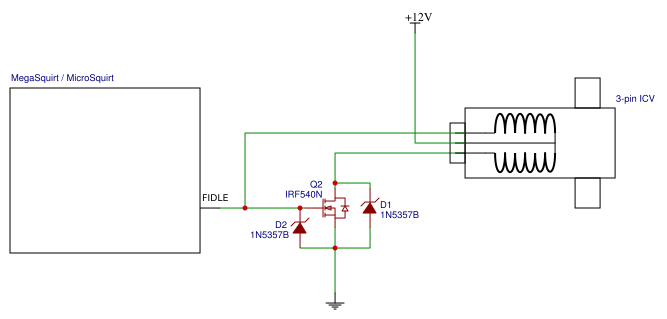
Net-net: MicroSquirt should do just fine when driving a single coil ICV without any external flyback protection. In my circuit, however, diode D2 is still needed to further reduce the voltage to protect the input to the transistor driving the second coil (Q2).
Quick status update: I’ve been putting in hours on the weekends to meet a deadline at work, so progress on this has slowed. Nonetheless I’ve managed to make good progress on a PCB layout, which is helping me to better map out the physical arrangement of things inside the case. Once I validate the design with my prototype, I should be able to quickly spin a PCB which, with some luck, should drop right in and work.
Last edited by Dare; 03-24-2019 at 01:15 PM.
Reason: Grammar
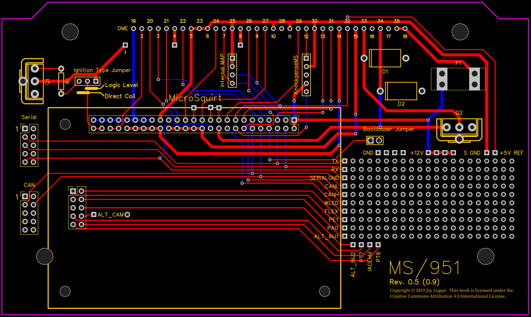
I thought I’d update this thread with a peek at the PCB layout I’ve been working on. This is still quite preliminary. But I’ve managed to incorporate most of the features I wanted, including a prototyping area with convenient access to various MS signals.
(Note that the image does not include the ground plane, which will cover most of the bottom [blue] layer).
This is my first real PCB design project, other than doing some toner-transfer stuff ages ago. So real EE’s, please go easy on me!
Awesome work! Have you made any progress since April? I just started ordering parts for converting my 924S to microsquirt in a couple weeks. I would really appreciate any PCB files you might have.
Sorry for the radio-silence on this! Crazy amounts of work and family obligations have forced me to put this project aside for a while. As I mentioned before, boards are in but I haven't had a chance to test them. With work travel and vacation coming up its probably not going to happen soon.
I developed the schematic and PCB layout using the EasyEDA site: https://easyeda.com/dare951/951-microsquirt. The project is publicly accessible so that anyone can make tweaks and build their own boards.
I do have extra boards if anyone wants to try one out.
I understand how obligations and projects don't mix! Hopefully you get some more free time eventually.
I'd love to try one out. You mentioned before you had noticed something wrong with the PCB. What is/was the issue?
Also, does anyone know if the 924s (same as late 944 NA?) DME pinout matches the 951 minus all the absent turbo stuff? I'll try to do some searching on that.
As it turns out, the problem I noticed wasn't really a big deal. I had meant to use a different, more readily available fuse holder, but I forgot to adjust the board layout. Since then I found a source for the original fuse holder and bought a bunch.
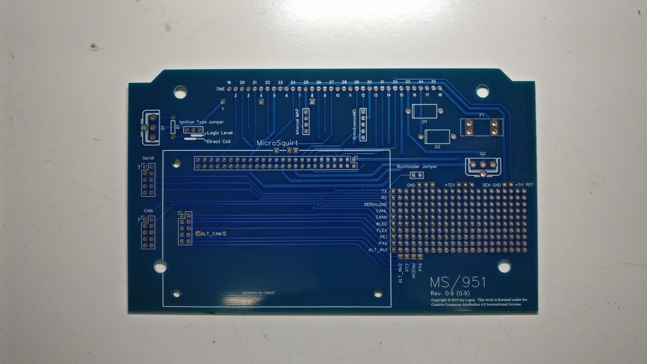
Perhaps the bigger issue is the choice of harness connector. I've been using the connector from a DME that is used in early '90s Saabs and Volvos. The connector pins form a single row where the pins interface with the PCB (see pic above). As it turns out, this style seems to have had a fairly narrow production lifetime, in between two other styles that use staggered pins. This has made it harder than I anticipated to source the connector. I'm pretty sure I can modify the PCB layout to accommodate both styles of connector, which would be an obvious upgrade to the design.
The other issue I've run into is mounting in the original case. Again, there's lots of seemingly unnecessary variance in the design of the base-plate which means that my board mounts correctly only in select DME cases. This is a bigger issue in my opinion, as one of my goals was for this project to be easy to construct from available parts. Because of this I spent some time sourcing a generic case to use as an alternative. I've found a good candidate, but as one might imagine, there's lots of mechanical details to be worked out that are all solved with the Bosch case.
Originally Posted by echoff
Also, does anyone know if the 924s (same as late 944 NA?) DME pinout matches the 951 minus all the absent turbo stuff? I'll try to do some searching on that.
I'm not familiar with the 924 at all. However, at least for the 951 and the 944 NAs, it's very easy to take the harness connector apart and re-order the pins. This requires no soldering and is completely reversible. So my guess is you should be able to adapt the 924 harness as well.
Wow you've thought a lot about making the project easy for others to replicate. It does seem that the Bosch case would be the way to go. Would removing the prototype area allow a smaller board to fit in a greater variety of the case designs?
I was able to find someone's wiring diagram from a 924s megasquirt project, and it looks like all the DME wiring is indeed the same as the 951 minus the turbo stuff. So no rearranging pins! Can't wait to get started once my hopefully single row of pins dead DME arrives.
I've been following this thread and Jay's work with some interest as I anticipate that, in the future, I will need to address what appear to be some problems with my own ECU. My "issue" is that I have an S2, and most of the development on these kinds of things tends to focus, appropriately, on the 8V and Turbo cars.
That said, I was thinking about some of Jay's comments on the connectors and ease of sourcing them and go to wondering about re-purposing connectors from a totally area: what about incorporating the use of ATX power supply connectors? There may not be enough pins (I haven't really counted) but from a supply perspective, I don't think you can go wrong and making space for 2 on the PCB if more pins are needed would be straightforward (I think, I've never actually done any of this kind of work, but Jay makes it sound like he could handle it no problem).
Anyway, just a thought. This is great work and I look forward to updates on the project.
I’m almost certainly getting ahead of myself, but I couldn’t resist pushing the button to order a few PCBs based on my preliminary layout.
I can already tell there’s one thing wrong. But what the hell, it was only 13 bucks for 6 boards!
Been watching your thread and definitely like your PCB layout I was wondering if this would transcribe to a MS2 or MS3 board? I like the extra protoboard especially
Here's a schematic showing the entire ICV circuit:
Note that one of the coils in the ICV causes it to open, while the other one causes it to close. The driver circuit inverts the FIDLE signal so that when one coil is on, the other is off.
MS doesn't seem to care which one is directly connected to the FIDLE pin. But this does make a difference as to whether 100% PWM duty cycle is all the way open or all the way closed.
Because MS doesn't care I haven't bothered to figure out which pin on the ICV connector is the open coil and which is the close coil. But it should be easy to determine.
By "explain the legs" do you mean explain why the terminals of Q2 are connected in this particular way?
Yes which leg gets what connection I'm a lil rusty or lacking in my electronic schematic reading.
On another note I like you PCB with the MicroSquirt was wondering if you thought about doing it with just the MS3 and MSX board you would only have to recreate a few circuits ie the Vref, IAT CL and the MAP I found a board the eliminates the VR circuit
 03-14-2019, 08:52 PM