When you click on links to various merchants on this site and make a purchase, this can result in this site earning a commission. Affiliate programs and affiliations include, but are not limited to, the eBay Partner Network.
16V 944S engine swap into pre 85.5 car - tips, info, and lessons learned
Hi guys, this thread will hopefully serve as a place to store information about swapping a 1987 16 valve 944S engine into and early square dash car. I'll be writing this by memory as I completed the swap last month, so if I miss anything or you have questions, let me know.
Second, while I rebuilt this engine and swapped it in, this post will focus more on the specific challenges of this swap, as there are already plenty of great guides about rebuilding and installing/removing 944 engines.
Parts List:
16V Engine (I bought an '87 off CL)
16V DME and AFM - The 16V AFM has a larger opening than the 8V, and the DME has 3 rows of pins instead of two. If you plan to use an aftermarket ECU, you likely won't need either of these.
16V Engine harness - You can make your own or perhaps adopt an 8V harness, but I have no knowledge about that.
16V Flywheel - You can use the 8V clutch and pressure plate
16V bellhousing - There are some slight differences in the castings between the 8V and the 16V, such as the cutout for the speed sensor. I would guess you can modify the 8V bellhousing to work, but I'm not sure.
Ignition control module - PN 928 602 706 01, referred to in the PET as "ignition switch unit." This fires the inition coil. It is needed due to changes made in the DME between the 8V and 16V engines. Make sure you get the aluminum plate/heat sink with it, as it can get hot.
Injector resistor pack - PN 944 616 523 00. Nothing too difficult here. Just plug it into the matching connector on the passenger side of the 16V harness.
16V exhaust - The 16V manifold, cat pipe, and muffler are roughly the same dimensions as the 8V exhaust, but they use different size/pattern flanges. If you are a decent welder, you could weld 8V flanges to the bottom of the 16V manifold and use the 8V exhaust from there back. You might need to adjust some hangers but it will work.
16V upper radiator hose - The 16V head coolant inlet is in a different orientation than the 8V. You will need the small hose from the inlet, the pipe to the radiator hose, and the upper radiator hose itself.
Fuel lines - You won't be able to use a factory part here. More on this below.
Intake air filter - Obviously, the 8V air box will not fit. The 16V box might fit but I think it would require some serious modifiction below the nose panel. I'm using a cone filter until I can design a better solution.
944S body harness (Optional) - Specifically the engine bay harness. This contains the wires you'll need to run the ICM, and you can cut them out. You can also wire it yourself, as it is only seven wires. Just be sure you use shielded wire for the ignition signal.
Various diameter vacuum hoses � The 16V engine has less vacuum hoses than the 8V, but if you plan to keep the charcoal canister system, you�ll need to reroute a few hoses to the proper places on the intake. I chose silicone hose. I recommend you label all the hoses on the 8V as you pull them off. That should be enough to help you figure out what goes where.
Wire and hose heat shielding (Optional, but recommended) � Pretty self explanatory. If you think it�s going to get hot and you don�t want it to melt or crack, wrap it. Many of your wires and hoses will probably not be where Porsche intended them to be and thus won�t be protected properly.
Miscellaneous wires, crimps/solder, and hardware.
I'm sure I'm forgetting a few things, but this is the bulk of it.
Mechanicals - You'll need to make some modifications to get everything to physically fit in the engine bay:
If you'll be using the stock S intake, the curved plastic tube will interfere with the drain pipe that extends from the driver side firewall. I cut about 15mm off the end of the pipe to fit the intake.
In an S car, the engine harness is meant to run through a hole on the passenger side of the firewall into the passenger side kick panel. I was able to bend my harness 180 degrees and send it along the firewall behind the engine and through the driver side firewall to the 8V DME location above the driver's feet. The DME plug on the 16V harness is larger than the 8V plug by a significant amount. I cut out some of the firewall around the stock harness hole to fit the plug as removing it from the wires is not practical. NOTE: I discovered this after the engine was in the car. I recommend you cut the hole with the engine out of the car, you'll have much more room to work. Make sure you add plenty of heat shielding around the harness where it runs behind the head as there is almost no clearance between the head and the firewall and it will get hot.
The early, cable controlled heater valve is behind the engine between the heater core and head coolant outlet. I found after I'd installed the 16V engine that the small arm on the valve that is pulled by the cable interferes with the firewall and doesn't allow you to turn off your heat all the way. It is almost impossible to access the valve after the engine is installed, so if you want working heat, you'll need to come up with a solution before installing the engine. I'd suggest relocating the early valve to the 16V valve location, just above the water pump by the oil filter, and extending the cable somehow. At the moment I have installed the 16V vacuum controlled valve in the stock location and will manually adjust the heat if necessary.
You'll need to fabricate mounts for the AFM, ICM, and injector resistor pack. I was able to mount everything without drilling and tapping any holes. You'll find that there are many unused, tapped M6 holes in the frame rails. They are covered with small black plugs. I was able to use these and some creatively bent aluminum to mount my AFM. It mounts just inboard of the coolant tank. There is a corrugated rubber boot between the AFM and the plastic intake tube, so you can build your mount to angle the AFM to suit whatever intake filter you plan to use. The ICM lives somewhere on the fender well behind the driver side headlight in the 944S. I was able to mount it using an unused stud on the frame rail. Put it in an area subject to some airflow, to allow it to cool, but obviously avoid areas that can get wet. The injector resistor pack is mounted somewhere near the cruise unit just behind the passenger upper shock mount. I no longer have cruise so I was able to use the cruise brackets to mount the resistors.
As mentioned earlier, the 8V fuel lines are non-reusable. The soft lines are attached to the hard lines at the driver side firewall with metal crimps. You can carefully cut these off and reveal a barb on the end of each hard line NOTE: do this while the engine is out of the car. It'll make your life much easier. You can then use injector hose and EFI clamps or you can cut the hard lines and use clamp on aftermarket soft lines as your 16V hoses. I did the former with no problems so far. I was forced to run my lines over the top of the intake manifold, as the engine harness took up all the space behind the engine. If you do this, I recommend heat shielding both lines and using a rubber clamp to hold them to the top of the intake (you can use the tapped hole that previously held the cruise cable).
If your 16V engine comes with its alternator, you won�t have any problem. The 16V alternator is physically lager than the 8V, and the aluminum bracket to mount it has a slightly wider opening. Long story short; you can run the smaller 8V with its bracket, or the larger 16V with its own bracket. You can�t mix and match. I decided to use the 8V, and have experienced no affects to the performance of the electronics.
Those are the only major mechanical changes needed. Other than that, I chose to take the time while my engine was out to scrub the bay, remove and old or cracked rubber, and replace or repair any parts that would be inaccessible otherwise. You�ll regret it later if you don�t. My clutch was almost brand new already, but this would also be a great time to change your clutch, throwout bearing, and pressure plate.
Electronics and Wiring � This was by far the most time consuming and patience testing part of the build for me, due mostly to my inexperience with it. If you have some knowledge of wiring diagrams, multimeter use, and the various electronics that run a 944 engine, this should be a very simple job. If not, I�m living proof that it�s not that hard to learn:
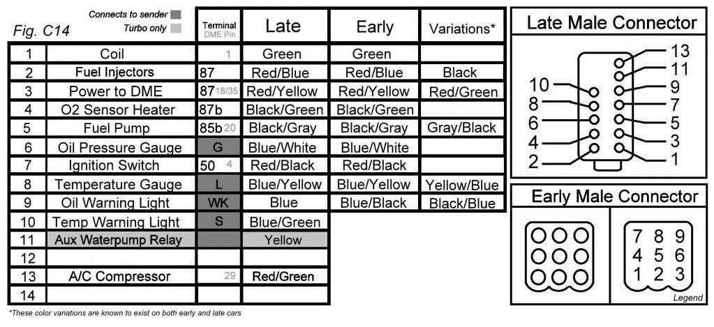
The main, and really only, connection that needs to be re wired is the connection between the 16V engine harness and the 8V body harness. The 16V engine harness uses a 14 pin black connector. The back of the connector can be popped off and the wires slid out to reveal a male pin on the end of each wire (NOTE: take a picture of how the wires are oriented in the connector before you remove them). The 8V body harness uses a 9 pin, white connector with female sockets matching the diameter of the male pins on the 16V connector. Conveniently, you can plug these in to test your configuration before finalizing your connections. This diagram was crucial to my success:
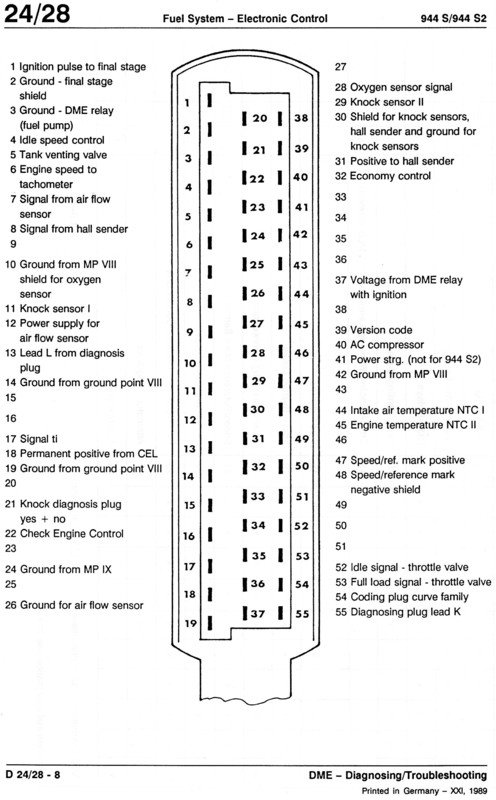
All credit to edredas on 924board via Odonnell�s thread here for this diagram:https://rennlist.com/forums/924-931-...nd-more-4.html I�m relying on memory here, which is risky for me, but I believe for numbers 2-9, you simply attach the matching wires to each other. You can verify by checking the female sockets with a multimeter to see how they react when the key is placed in different positions, etc. numbers 10-14 were only used for 16V gauges and aren�t necessary if you�ll be using the early gauges. Wire #1 is your ignition signal. The 8V body harness socket #1 will be wired straight to your coil if you haven�t removed the wires already. You�ll notice that on the back of the connector at the #1 socket there is a large green wire (to your coil) bundled with a smaller green wire that goes to the firewall. This smaller wire goes to your tach. More on this later. The 16V uses the ICM to fire the coil, so you don�t want to put your ignition signal into the #1 socket on the 8V harness, you want to put it into the third pin on your ICM. The first wire on your ICM, if you used the stock wiring, will be a large green wire shielded with a black wire. It will have a socket on the end of the inner wire and the outer wire (shield) that you will connect to the 16V engine harness. The inner green wire connects to the #1 pin from the 14 pin connector. On my harness, there was a black wire and pin in the #14 position that happened to be the shield for the ignition signal, eventually going to pin 2 on the DME. For a good pinout of the 16V DME, see here:
If you�re ever unsure of what wire in the engine bay goes where on the DME, I found it helpful to attach a long lead to the engine bay side and set my multimeter to test continuity. Remove the plug from the DME and probe the suspected pin on the plug. If you hear the tone, that�s your wire. If not, keep guessing. You can also test all your grounds by doing this same test but grounding the other lead. There was one wire that kept my car from running for over a month; see pin 18 on the DME pinout: �Permanent positive from CEL.� This will likely appear as an unknown red wire that was originally in the 14 pin bundle on the engine harness. Long story short, this wire needs a constant 12V while the engine is running. I wired it directly to my battery to test, but this has resulted in my battery draining while the car isn�t running. I�m investigating finding an unused fuse under the dash that is switched by the ignition switch to power this wire and solve the problem. If your car fires but won�t start, investigate this wire.
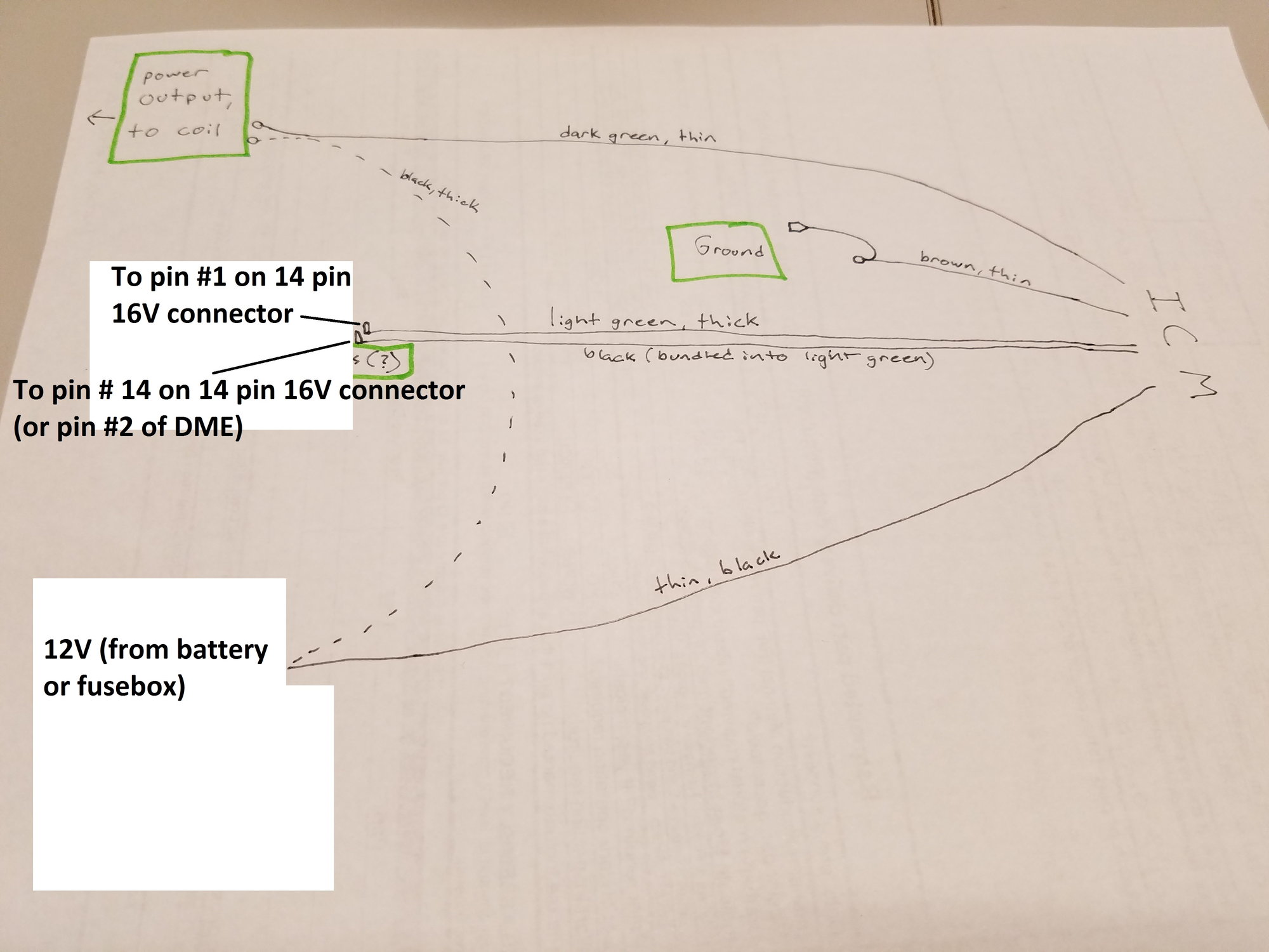
The ICM, as mentioned earlier, is fairly easy to wire. It uses 6 wires to control the ignition signal, as shown this (crude) diagram:
The first two wires will have copper loops on the end and will attach to the two pins of the coil. The green wire goes where the 8V green wire went, and the black where the 8V black wire went. There is a small brown ground wire, I found a pre tapped hole in the frame rail for an M6 bolt and cleaned it up so there would be a good connection. The large bundled wire is the wire mentioned earlier that will have sockets on the end and connect to the 14 pin 16V connector. The last wire is the power source, it will be a black wire and have another wire that bridges to it from the coil as seen in the diagram. This will need a constant 12V while the engine is running. It was originally fed from somewhere in the dash.
If you�ll be using the early gauges, wiring the tach is fairly simple. As mentioned earlier, the smaller green wire on the back of socket #1 on the 9 socket 8V connector goes to your tach. Since you�re no longer using this socket to deliver the ignition signal, you�ll need to find a way to get that small green wire the ignition signal. I found the easiest way was to simply leave the larger green wire connected to the socket and the coil terminal. The tach will not work with just the ignition signal, it will also need the fuel injector signal. There should be a 2 wire white leftover connector hanging above the driver�s feet that used to connect to the 8V engine harness. It will have a black wire and a black and yellow wire. The black wire needs the fuel injector signal. You can splice a wire from the connection in the engine bay (pin #2 on the connectors diagram, a red/blue wire), and run it through the firewall to this black wire. The tach should now function properly. The fuel consumption gauge will not. I imagine this would require the black/yellow wire to get a signal, but I�m not sure what.
For the starter/battery/alternator harness, use the harness that matches whichever alternator you decided to use.
There is a gray wire that clips to the front of the timing cover and runs down to the power steering pump area. It will have a boot on the end with two copper connectors in it. This was originally connected to the 16V power steering pump and would raise engine revs if the DME sensed the pump was struggling. If you leave this plug hanging or tied up with the leads exposed, it can cause a weird surging idle and random hanging when the revs should be dropping as the leads touch each other. Ask me how I know.
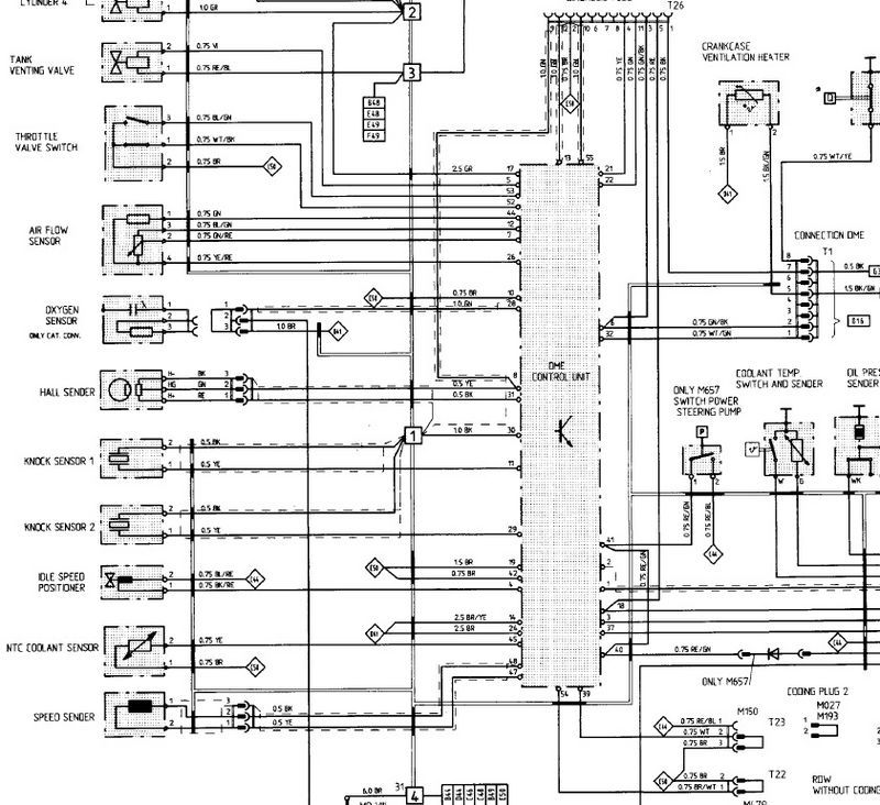
The last diagram I�ll throw in here is a 16V engine bay wiring diagram that I found helpful. It�s split in half:
I apologize for the lack of pictures. My garage is dark and I�m no photographer. If I come across anything helpful I�ll add it here. If you have any information to add or spot a mistake, let me know. For the record, I have about 200 miles on the engine so far and have loved every one of them. It was a lot of hard work and ate a good deal of my paychecks, but the 16V is a notable upgrade from a tired old 8V and I�m happy to have learned a bunch of new things about the 944. Thanks!
-Mike
Some added notes that might be useful for future swappers.
FYI, porsche cast the 87 944S bellhousings with the notch cut out, but later backtracked. If you ever have a "kickback" on startup issue, get the updated bracket and Sleeve for the Ref sensor from porsche to eliminate the issue. The issue is the magnetic interference from the starter messing with the sensor without that shielding. this is more of an issue of you use the smaller, "late" style starter vs the bigger early starter.
The S and S2 use the same clutch/PP as the 8v. So use whatevers best, the flywheel is the only difference. If you get a 968 engine, the S/S2 bellhousing, flywheel and the clutch will let you install the engine to a 924/944 torque tube.
The S2 is the same wiring wise as the S (same DME series), the 968 adds variocam but is also based on the same architecture. The 16V stuff it's own family.
The S/S2 header is the same, they both work with the 968 engine as well. My 968 swap uses my cars original S2 exhaust, the S/S2 full exhaust should bolt in to the early chassis if you have it to use. The 968 exhaust from the header back is different/
If you wanted to go really hard, the 944S dash, hvac and body interior harness would swap into the early chassis. You'll need to drill a few holes to make it happen, you'll also need to take the A/C lines, which need to go in before the motor does.
Thanks Arominus. You reminded me that I forgot to mention that I run a manual steering rack and deleted the AC long before the engine swap, so if you decide to do this swap you may want to check that those systems will fit if you plan to keep them.
You would only need to swap from the early AC lines to the late ones if you swapped hvac systems. The manual and power racks both work with the swap without issue.
Hi. Thank you for very helpful information.
Yesterday i was supposed to start up my rebuildt S engine that is swapped into a 8v late model. Unfortunately it would not start. No spark, no fuel and no tach bounce. Investigating the problem i luckily found this topic. And you introduced me to a new part, the ICM . This is now ordered. But i dont have the original wires or the connection. Can you please tell me where the different wires on your drawing will connect on the different ICM pins?
Thank you,
Martin
Hi Martin,
I believe the wires in this image:
attach as if you were looking down on the ICM from the top, meaning the dark green wire goes to pin #1, and the thin black wire goes to pin #5. I could be wrong though, so you might want to wire it up that way in a way that is easy to change if you find you still don't have spark. That being said, if you have no fuel, spark, or tach bounce, you've got bigger problems. Do you have the injector resistor pack for the S? I think it's unique for the S sized resistors. That might explain no fuel. You might not have tach bounce because you probably don't have the tach hooked up properly, but I would have guessed it was plug and play with a late 8V harness.
As listed above: "Injector resistor pack - PN 944 616 523 00"
I don't know what the number you listed above is, but it does not appear to be a standard porsche part number. If I remember tonight, I can take a look at mine and see if it has that number on it.
Martin, I checked my resistor pack last night and it has your same (Bosch) part number on the case. This leads me to believe you have the correct part.
Thank you Mike!
New question: on my 14 pin connector from the16v harness there is no pin/wire at #7. I understand that this is needed for the dme relay to engage the fuel pump?
I will try to connect #7 to 12v from the battery tomorrow, hopefully it will work then.
Do you know witch pin on the dme connection should be connected to #7?
(Fuel pump works when bypassing dme relay, and i have 12v on pin 37/24 at the dme connection.)
 03-12-2018, 04:49 PM