
Projects on my new, to me, 1974 914-6
 09-27-2018, 08:13 PM
#61
Racer
Thread Starter

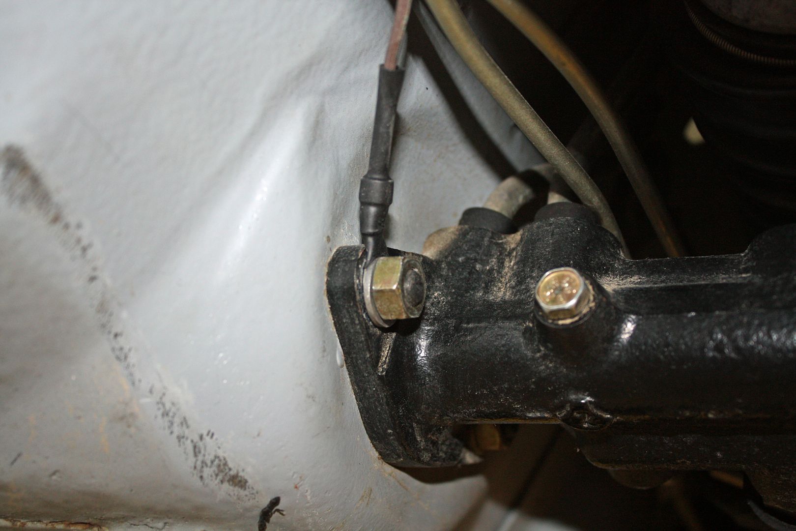
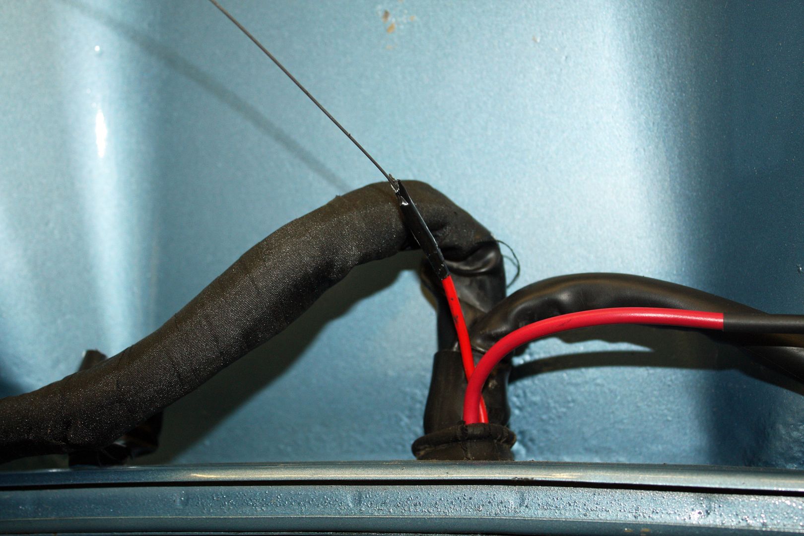
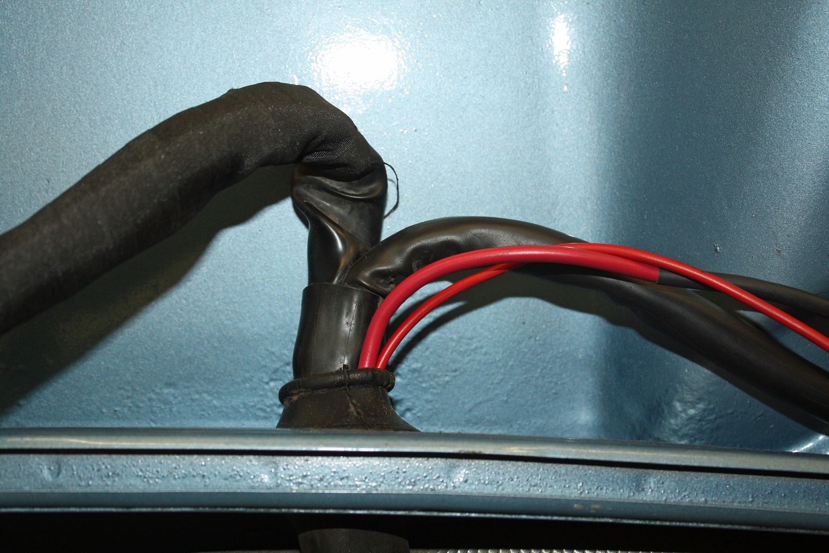
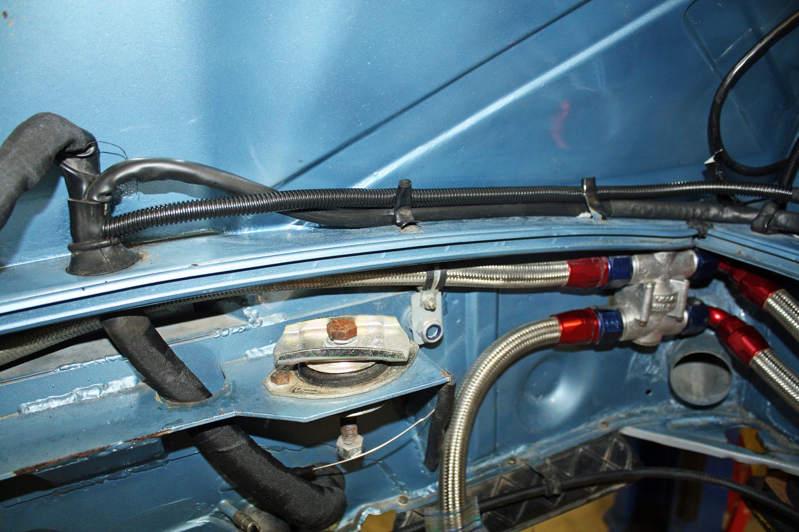
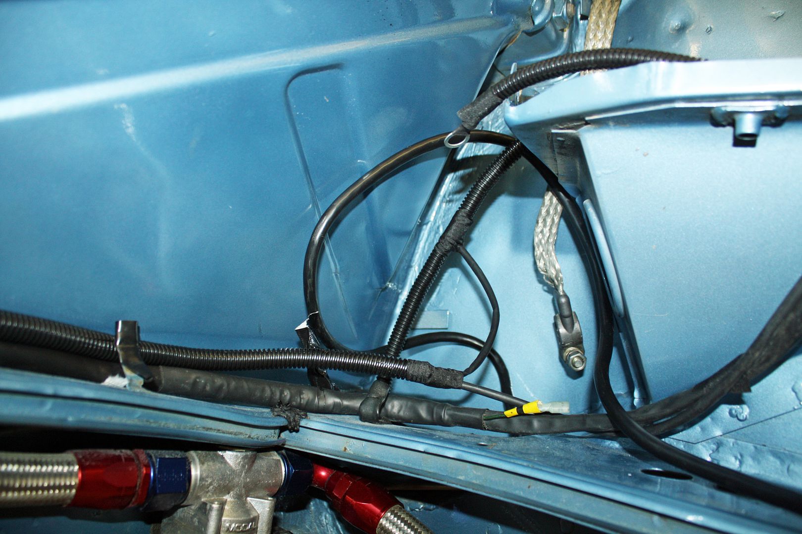
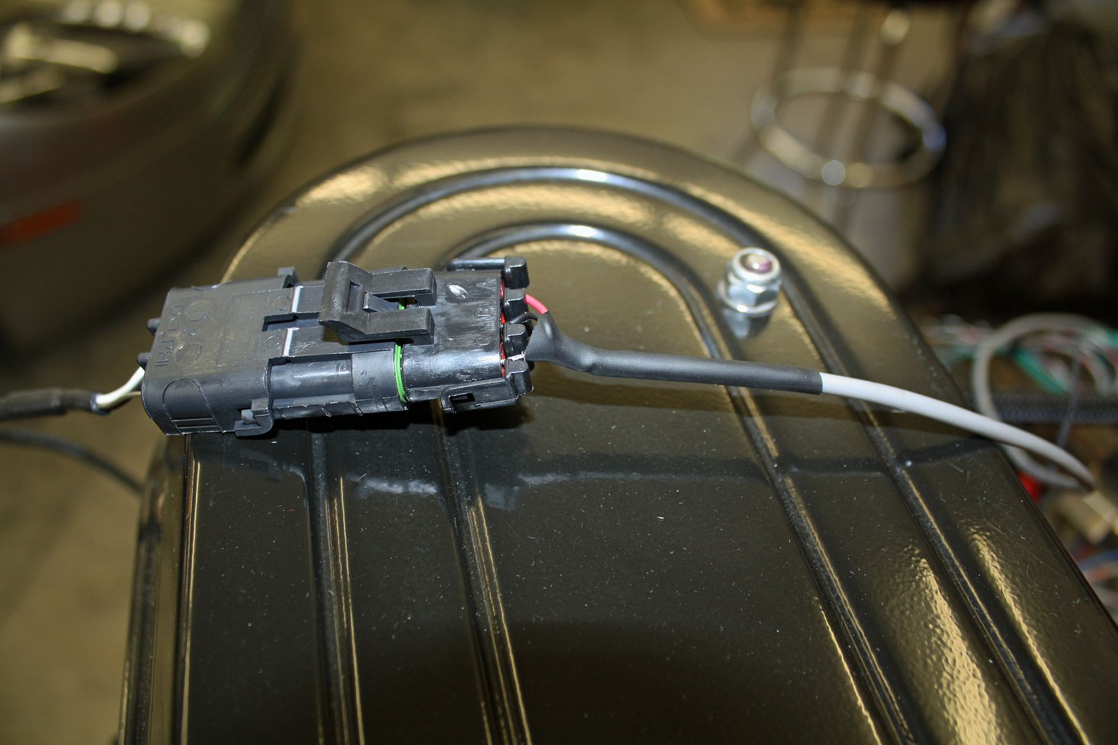
Now I could finish up the fuel pump wiring. I used a ground on one of the bolts for the master cylinder and ran the plus wire out of the fuel tank bay to the pump.
At the other end of the car, I couldn't find a good way to get the wire up to the battery area and then back to the trunk. I finally decided to remove all of the fabric tape I had applied to the wiring harness and rout the wire up through the harness and then over to the right side of the engine bay. I used a wire to pull the wire up through the harness boot. After soldering the wire from the front of the car to the wire from the power harness and running it over to the negative lead for the battery, I re-applied the fabric tape to the wiring harness boot.


At the other end of the car, I couldn't find a good way to get the wire up to the battery area and then back to the trunk. I finally decided to remove all of the fabric tape I had applied to the wiring harness and rout the wire up through the harness and then over to the right side of the engine bay. I used a wire to pull the wire up through the harness boot. After soldering the wire from the front of the car to the wire from the power harness and running it over to the negative lead for the battery, I re-applied the fabric tape to the wiring harness boot.


 10-02-2018, 05:56 PM
#62
Racer
Thread Starter
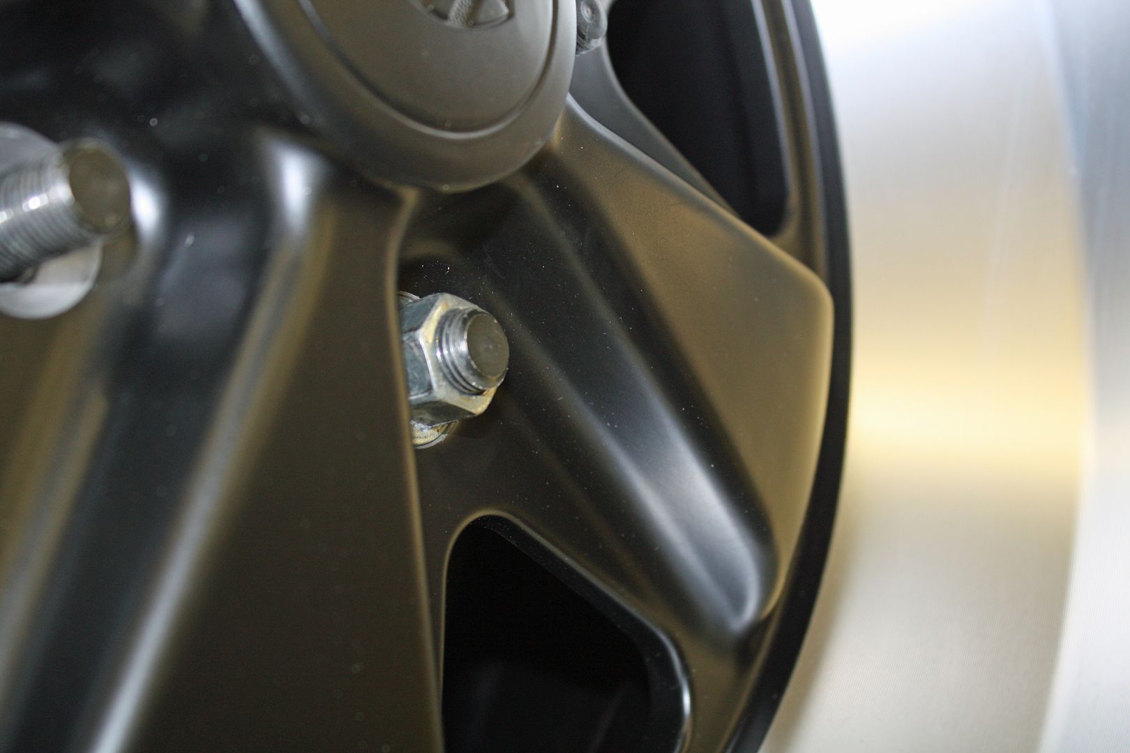
After being busy with other things the past few days, I got back to working on the car today. After installing the new wheels, the wheel studs for the rear were the right size but the front ones were too short. I did some measuring and ordered ten 56mm studs for the front wheels.
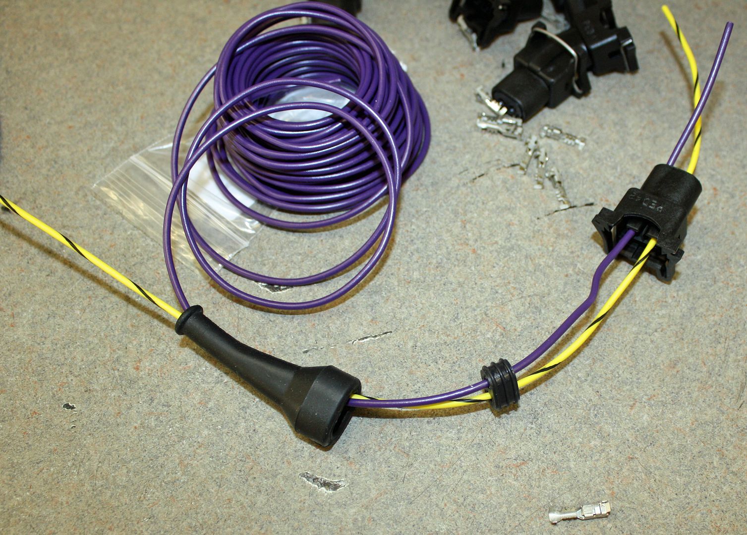
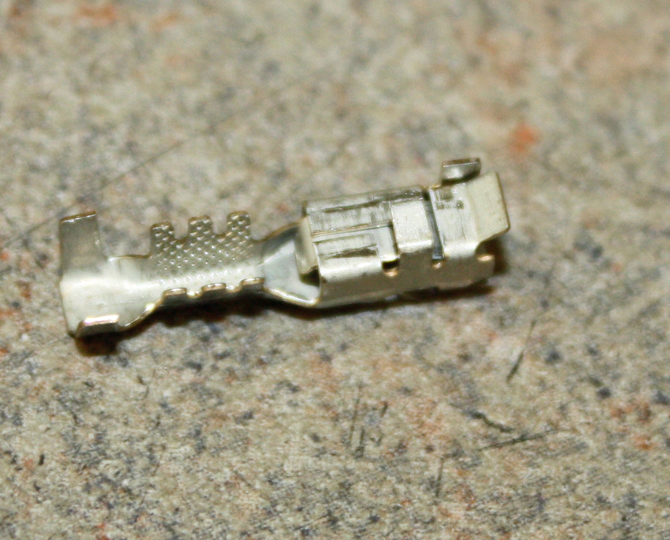
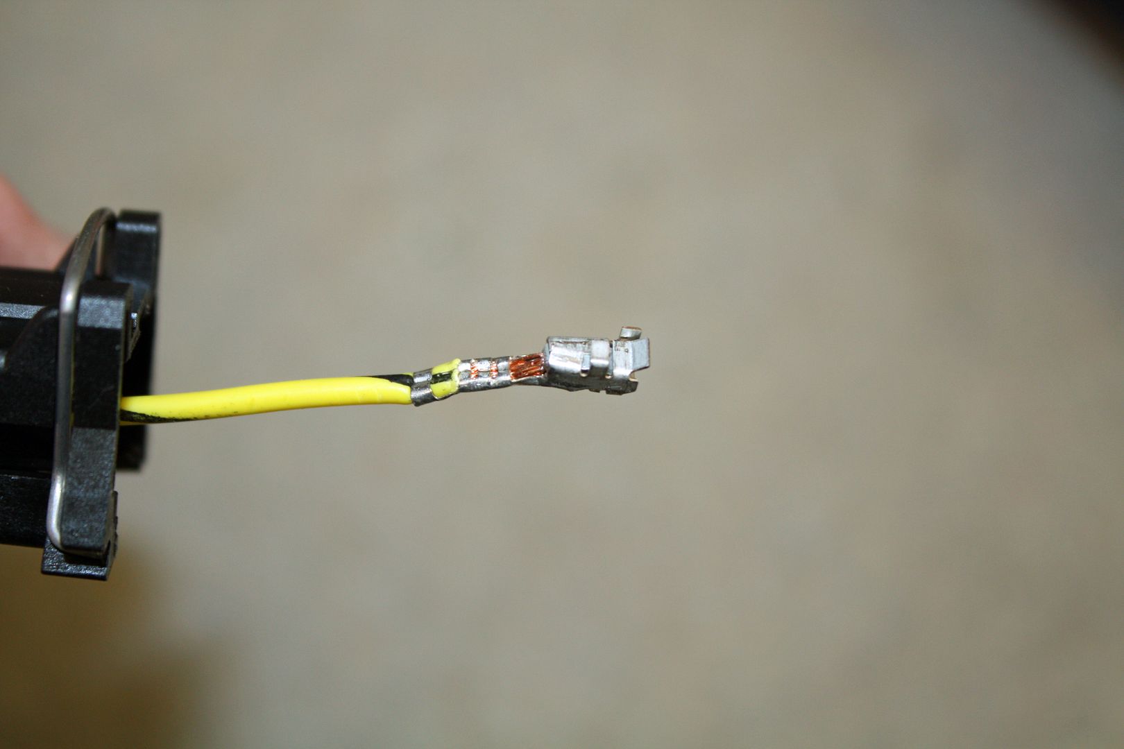
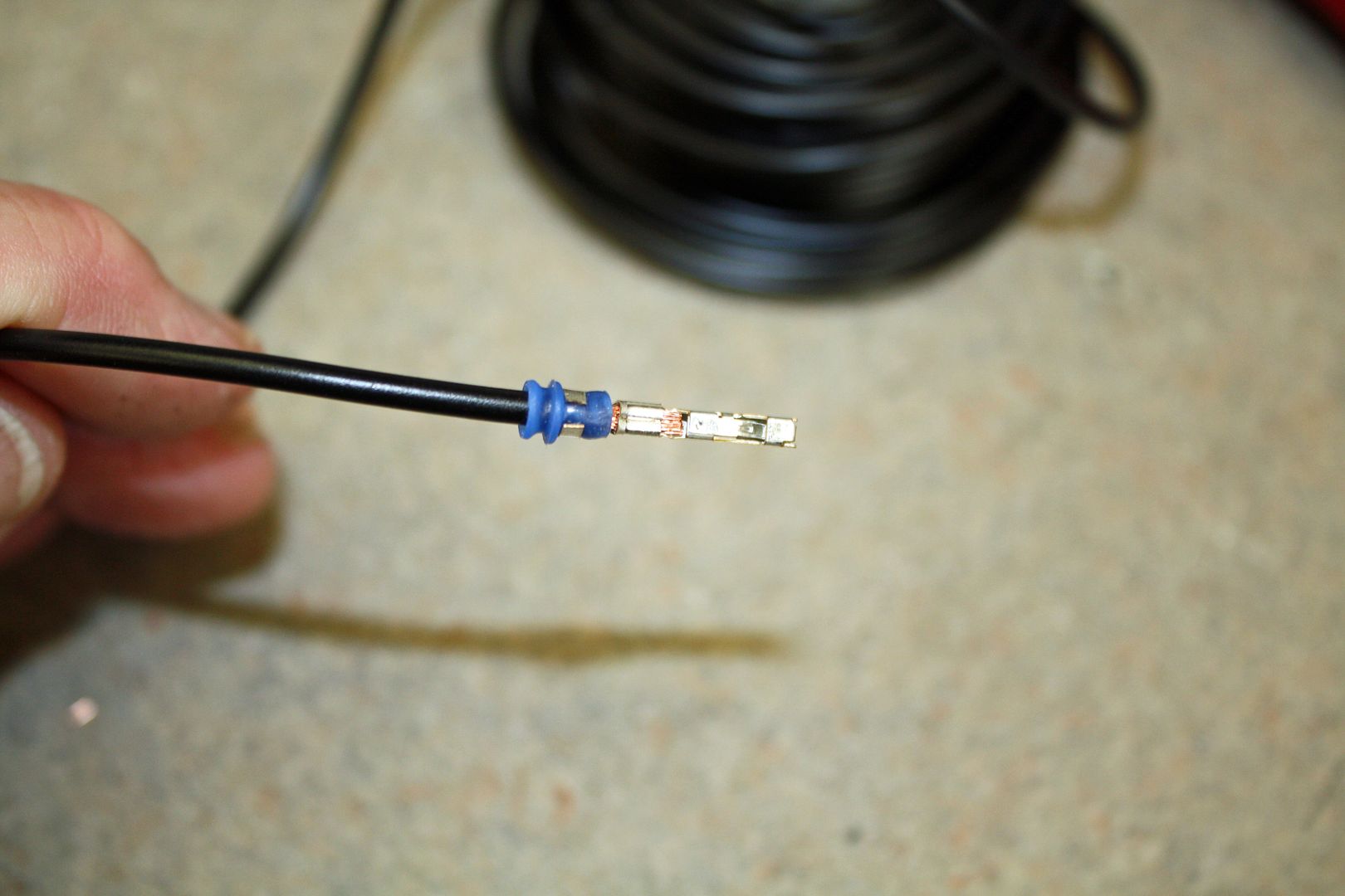
This afternoon I began wiring the harness for the fuel injectors. I have done quite a bit of wiring in my past but this is the first time I have worked with weatherpack connectors. So there is a learning curve. The fuel injector plug uses a GT-150 female terminal. The seal is built into the plug so it does not use a seal on the wire. Richard Clewett says he uses the weatherpack crimper with all of the connectors in his kit. After some trial and error, I figured out how that crimper worked with these terminals. But not until I had already used up the extra three terminals, and then some, that Richard had sent. I have more on the way.
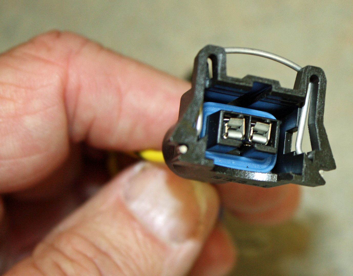
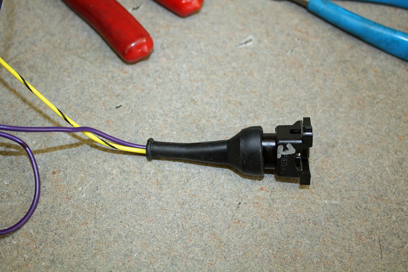
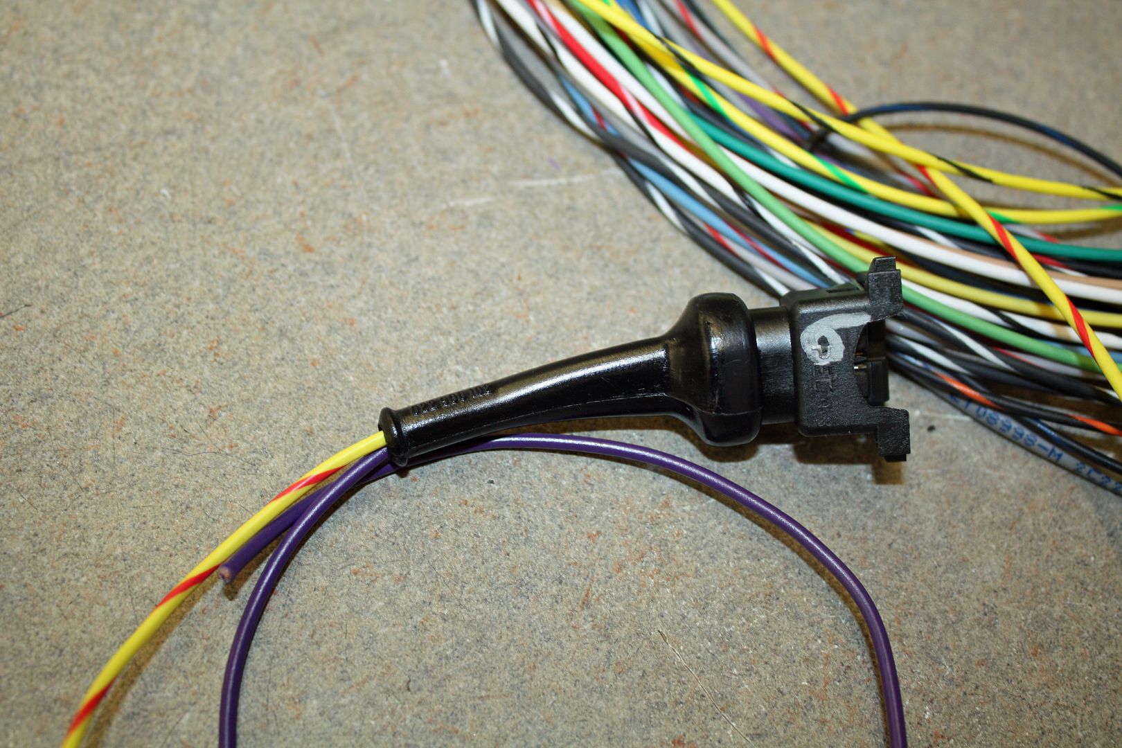
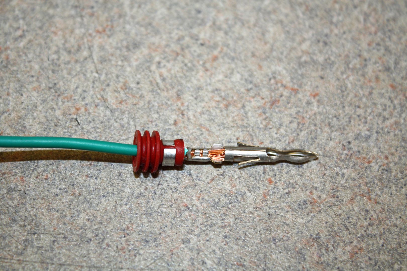
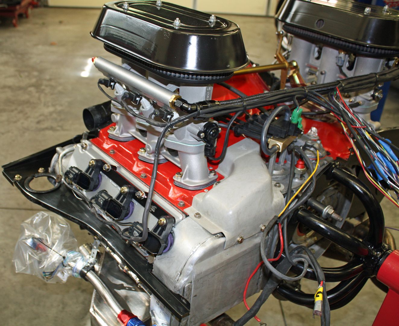
There are pull through terminals which means the wire has to be run through the plug, the terminal crimped and then then the wire is pulled back to lock the terminal in place. With the terminals in place, i can re-insert the seal into the plug. At Automobile Atlanta, I found these fuel injector boots. They may not be necessary but add an OEM touch to the wiring.
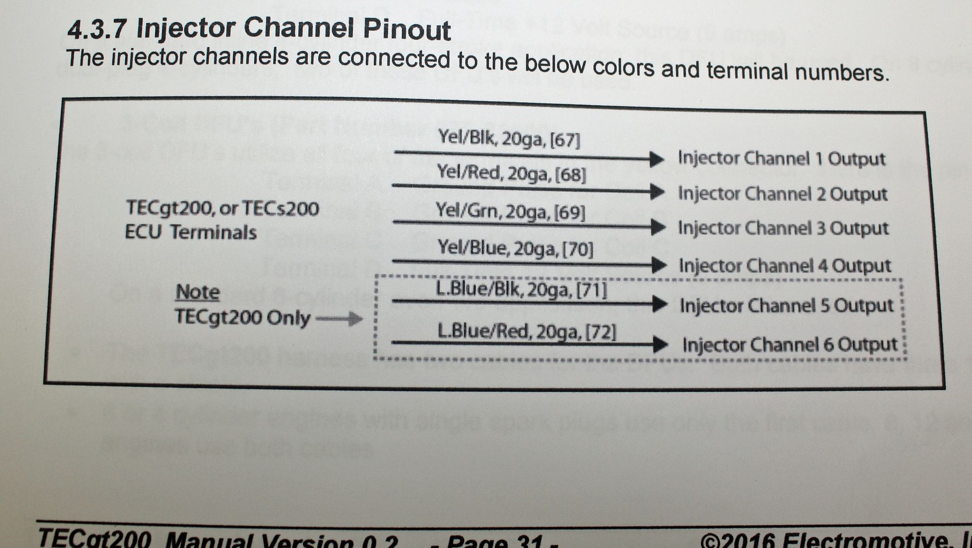
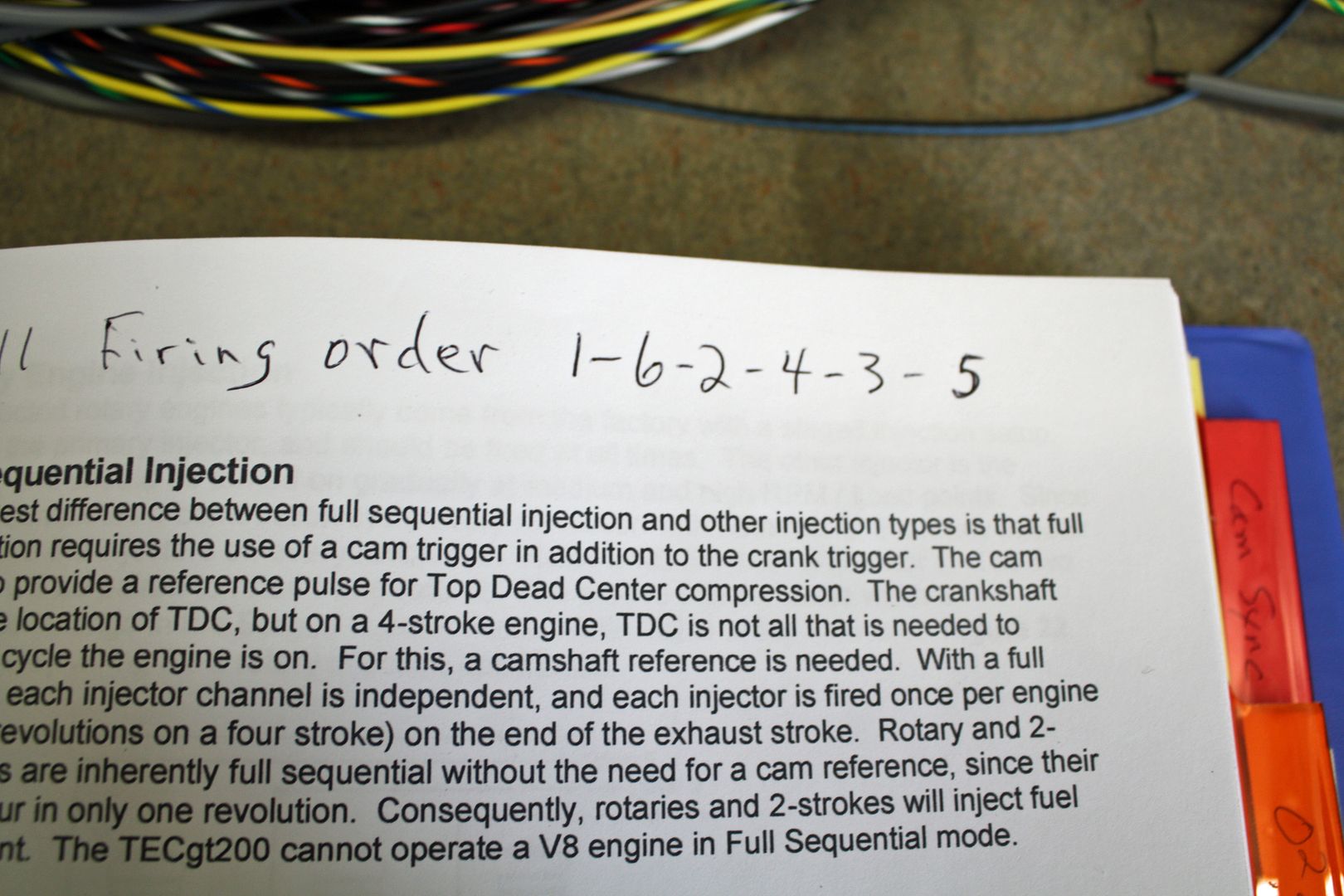
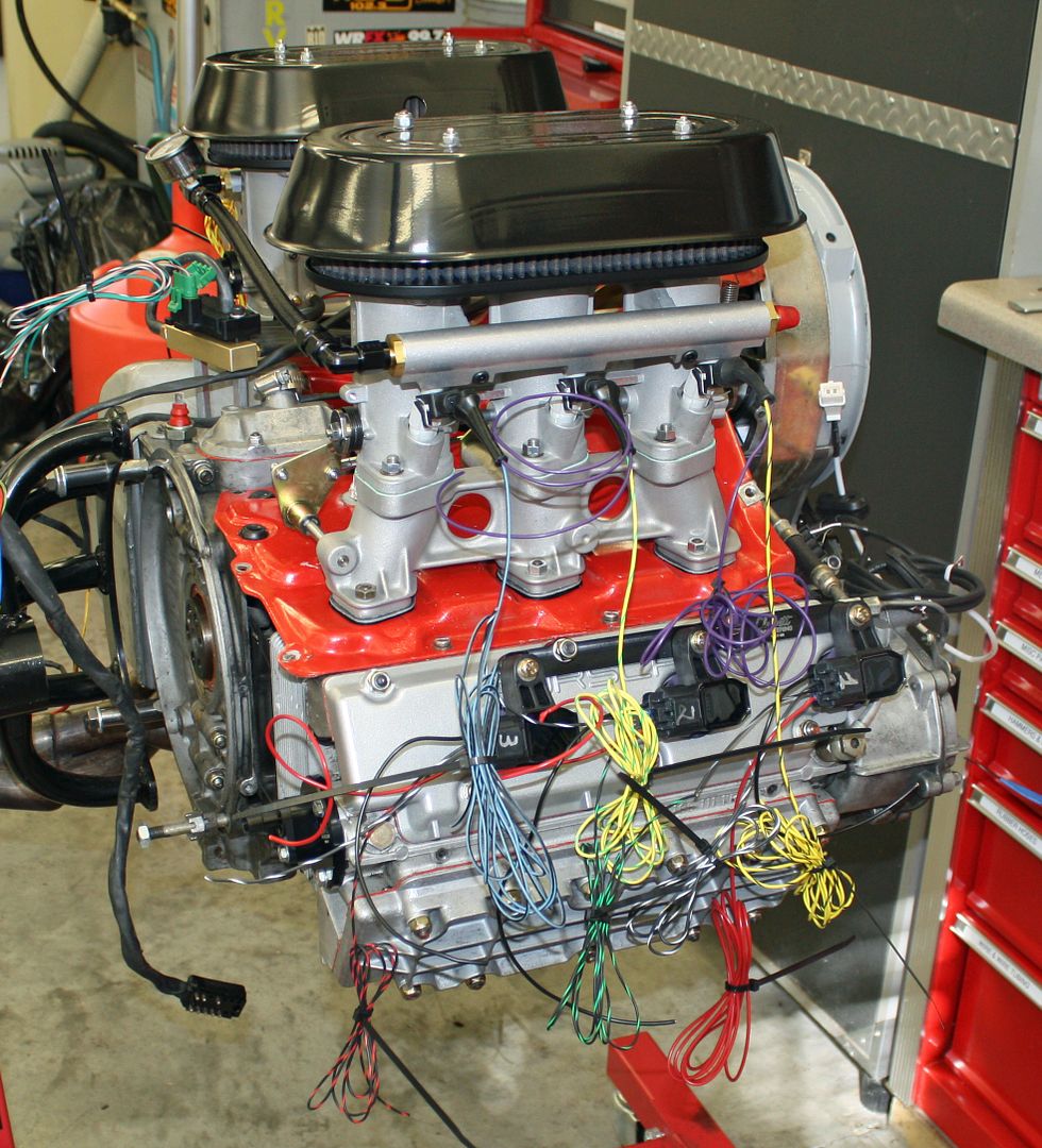
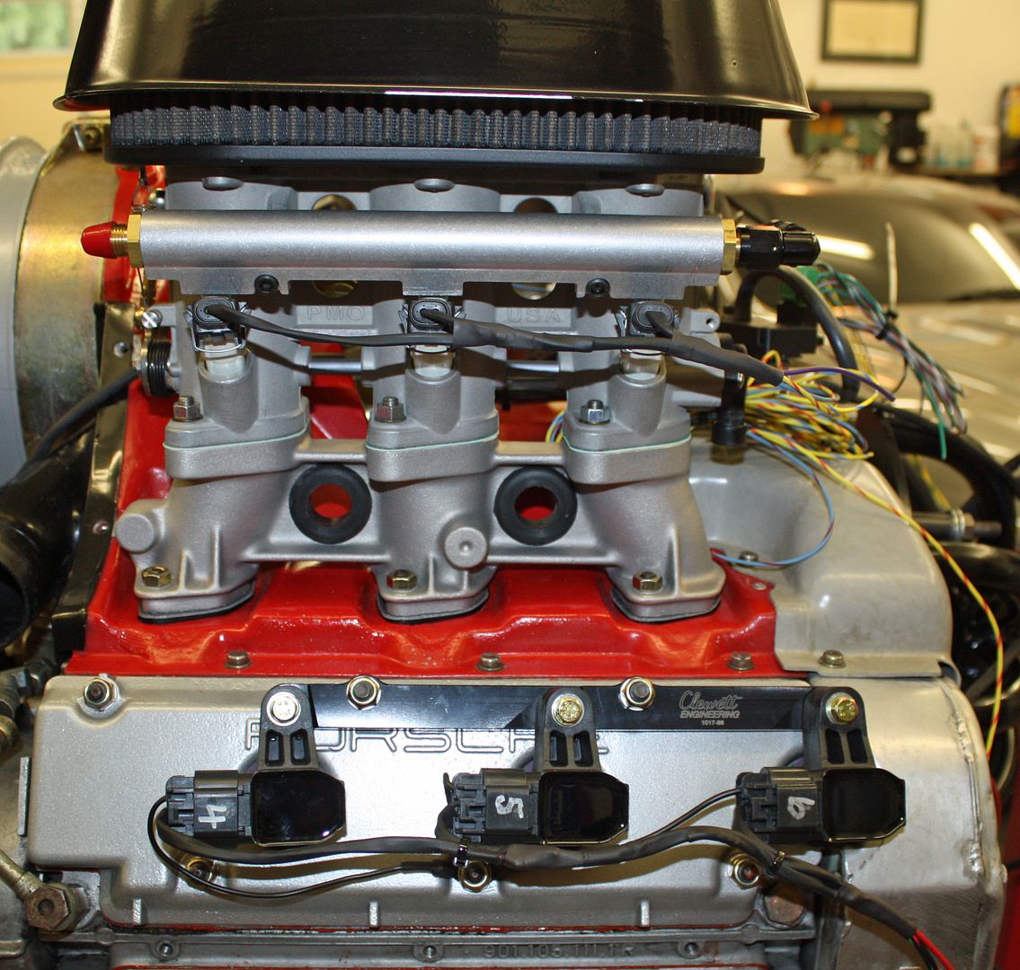
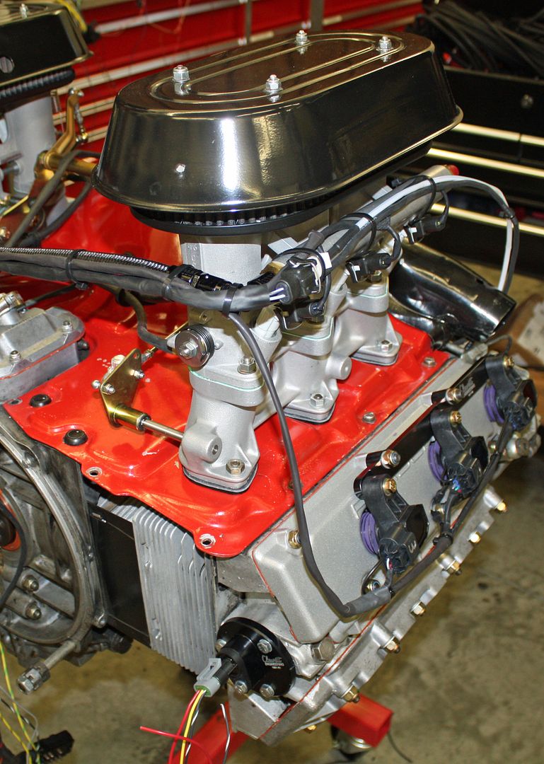
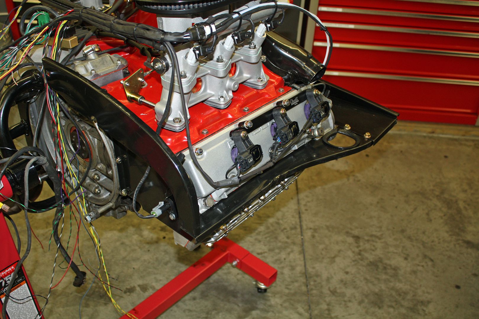
The TEC GT-200 ECU is capable of running a number of different types of fuel injection. Richard's kit is set up for sequential fuel injection which explains the need for the cam sensor. There are six output channels from the ECU. Channel one goes to the first cylinder in the firing order, which on a 911 engine is cylinder one. Channel two goes to the next cylinder that fires, cylinder six in a 911 engine. It is critical that the output channels are wired to the corresponding injector.
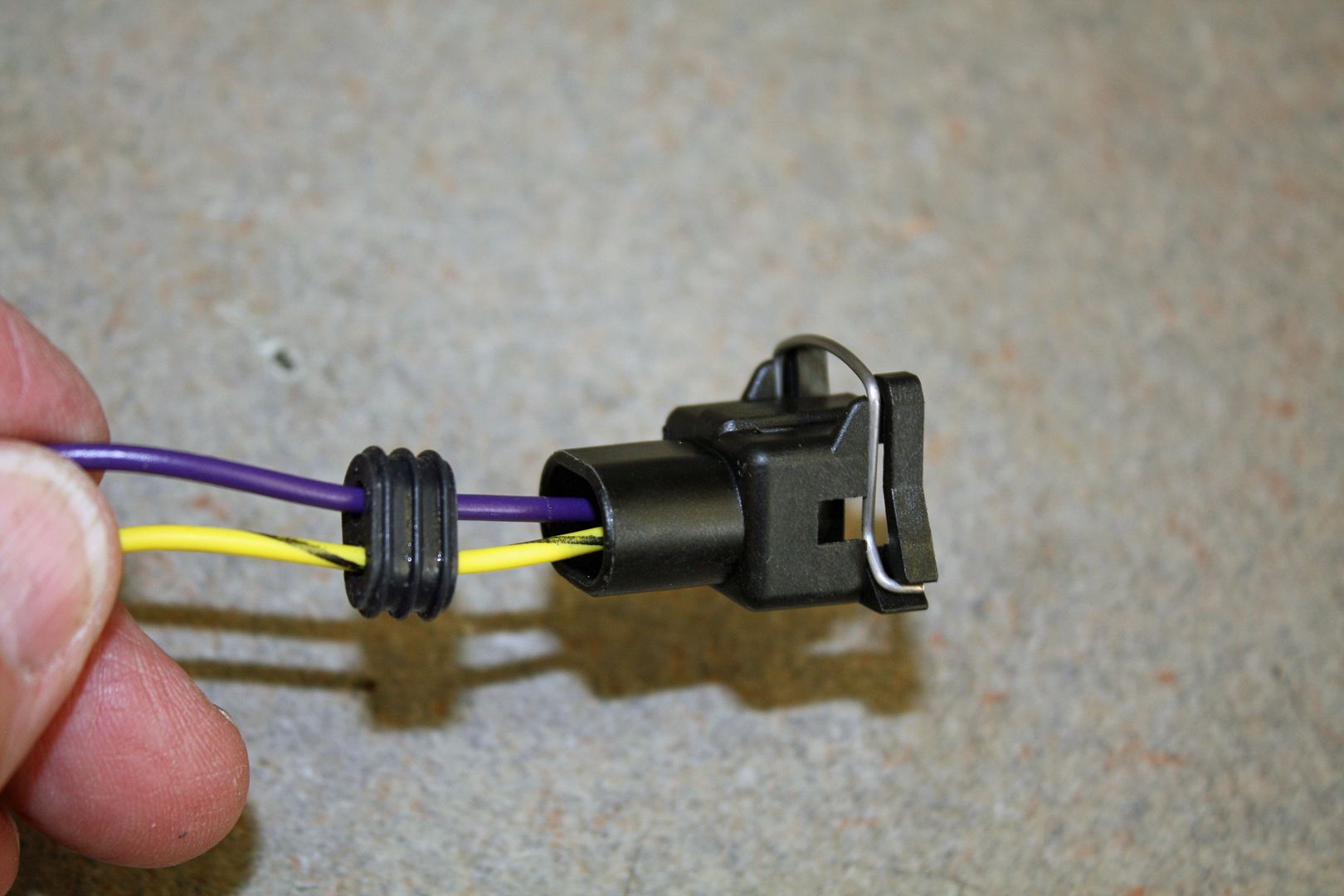
The output channel wire goes to the left side terminal of the injector. The right side is connected to the purple/white wire in the power harness. The injectors in wired in parallel so every injector's right side terminal will be the wired to this same wire. I couldn't find a purple/white wire locally so this solid purple wire will have to suffice.
This afternoon I began wiring the harness for the fuel injectors. I have done quite a bit of wiring in my past but this is the first time I have worked with weatherpack connectors. So there is a learning curve. The fuel injector plug uses a GT-150 female terminal. The seal is built into the plug so it does not use a seal on the wire. Richard Clewett says he uses the weatherpack crimper with all of the connectors in his kit. After some trial and error, I figured out how that crimper worked with these terminals. But not until I had already used up the extra three terminals, and then some, that Richard had sent. I have more on the way.
There are pull through terminals which means the wire has to be run through the plug, the terminal crimped and then then the wire is pulled back to lock the terminal in place. With the terminals in place, i can re-insert the seal into the plug. At Automobile Atlanta, I found these fuel injector boots. They may not be necessary but add an OEM touch to the wiring.
The TEC GT-200 ECU is capable of running a number of different types of fuel injection. Richard's kit is set up for sequential fuel injection which explains the need for the cam sensor. There are six output channels from the ECU. Channel one goes to the first cylinder in the firing order, which on a 911 engine is cylinder one. Channel two goes to the next cylinder that fires, cylinder six in a 911 engine. It is critical that the output channels are wired to the corresponding injector.
The output channel wire goes to the left side terminal of the injector. The right side is connected to the purple/white wire in the power harness. The injectors in wired in parallel so every injector's right side terminal will be the wired to this same wire. I couldn't find a purple/white wire locally so this solid purple wire will have to suffice.


 10-03-2018, 05:17 PM
#63
Racer
Thread Starter
After making a Sam's run this morning, I finished up the wiring on the fuel injectors, save one where I had used up all of my terminals. The additional terminals are supposed to be here tomorrow.
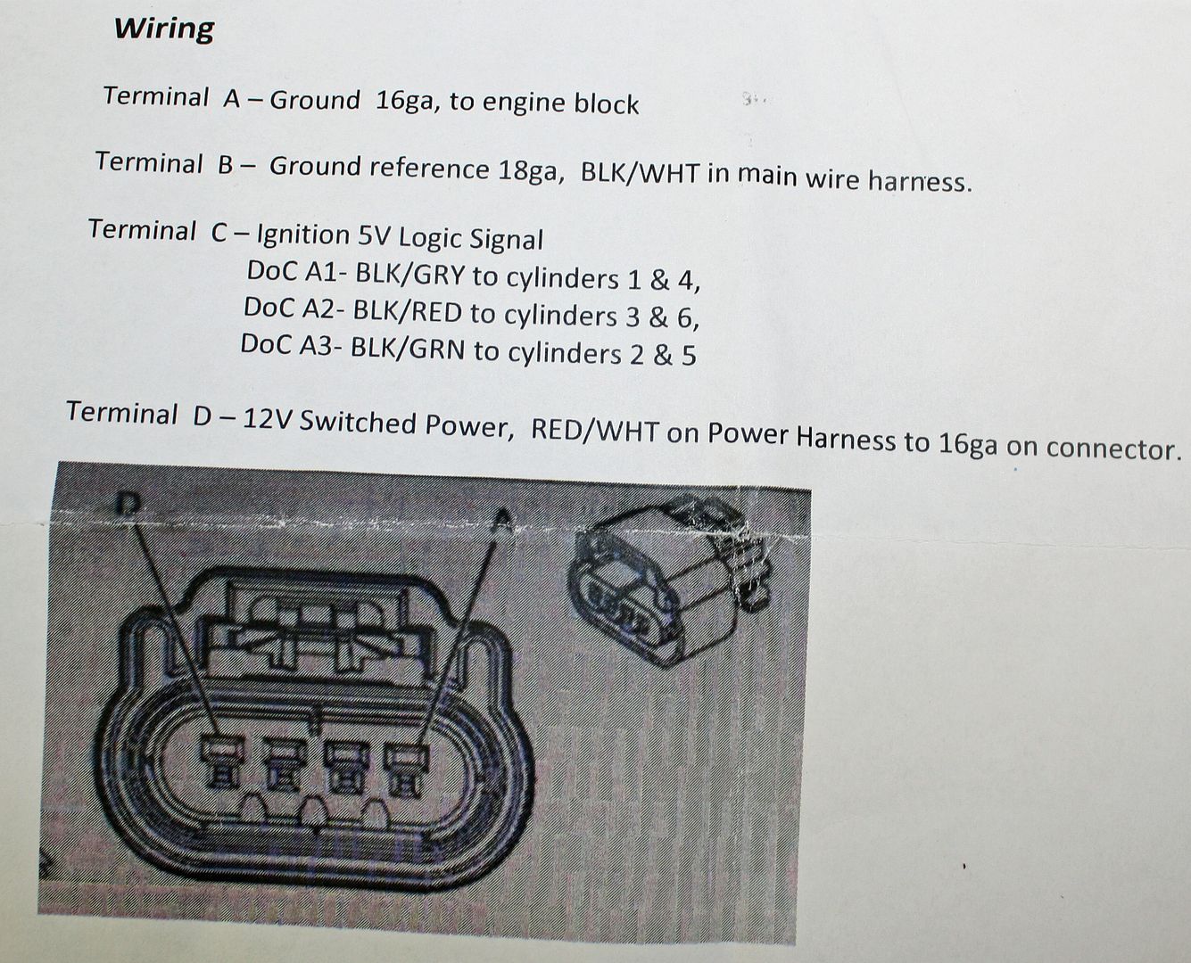
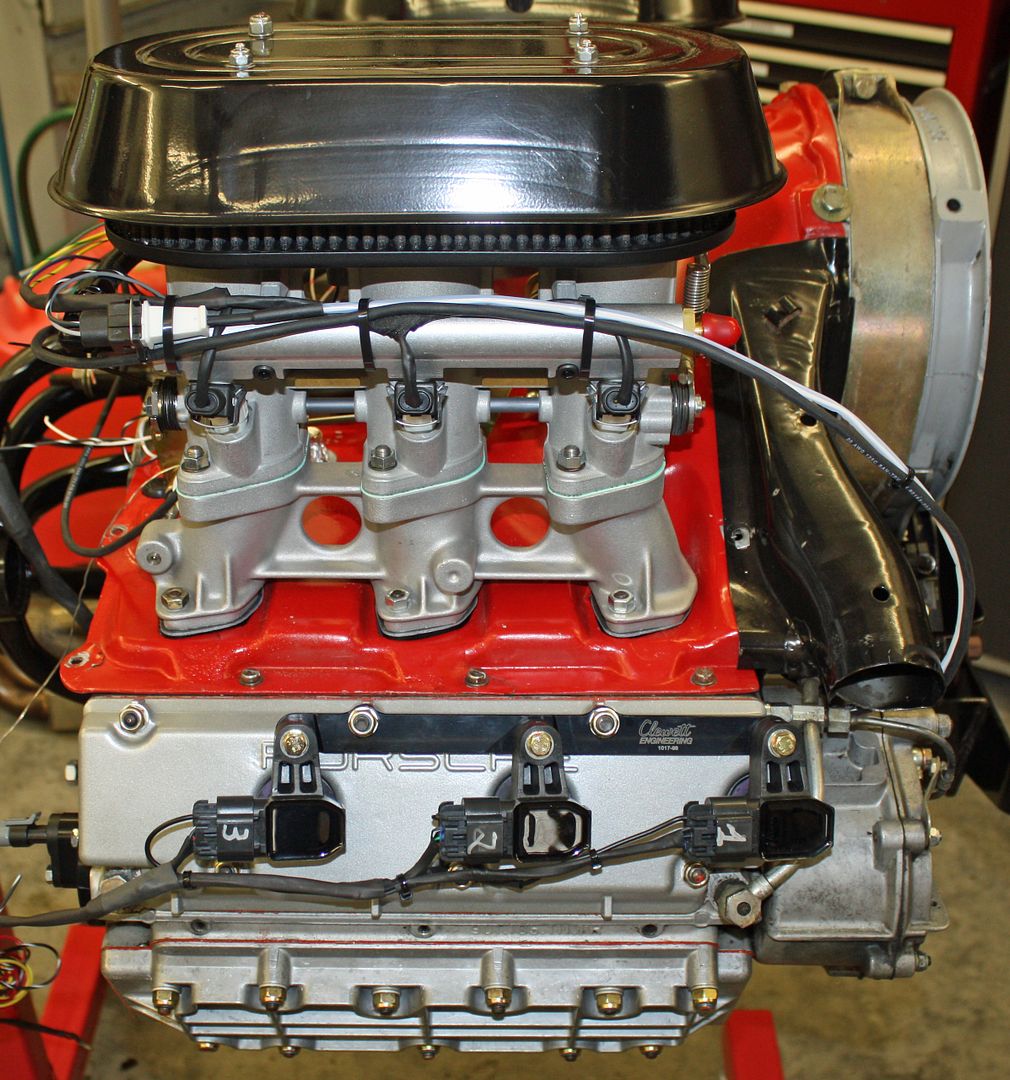
I then moved on to the wiring for the Coil On Plug's (COP). The terminals for these plugs used the weatherpack seal on the end of the wire. Another learning curve happened here and I progressively became faster at doing the wiring as the afternoon wore on. However, it was time consuming making the crimps and then getting the terminal to seat in the plug. I can see why Richard charges $900 for a custom wiring harness.
There are four wires to each of the plugs. One is a ground to the engine. Another is a reference ground from the ECU. Another is a 12V source while the last one is the firing signal wire for cylinders. One wire fires cylinders 1 & 4, another fires cylinders 3 & 6 while the other one fires cylinders 2 & 5.
The COP's that came with the kit had a tab that prevented the plug from being attached. A call to Richard confirmed that those tabs needed to be cut off. He said he was having trouble getting the parts and that these COP's could be used with another plug as well as the ones that came with the kit. The tabs were easily removed.


 10-04-2018, 05:42 PM
#64
Racer
Thread Starter
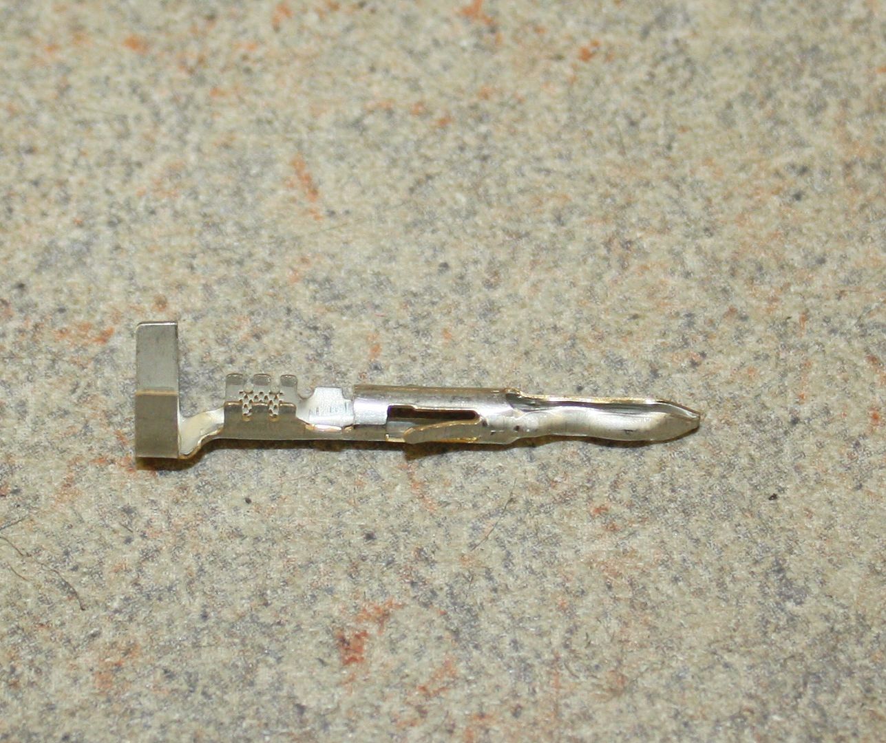
I finished up the COP plugs today. The terminals used on both the injector and COP plugs are called metripack. The MSD crimper die I have is for the weatherpack terminals. Richard says he uses the weatherpack crimper for all of the terminals. I struggled with that a bit as I had to do the crimp on the seal again to make it small enough to fit into the plug. That's one reason why it took me so long to do these crimps.
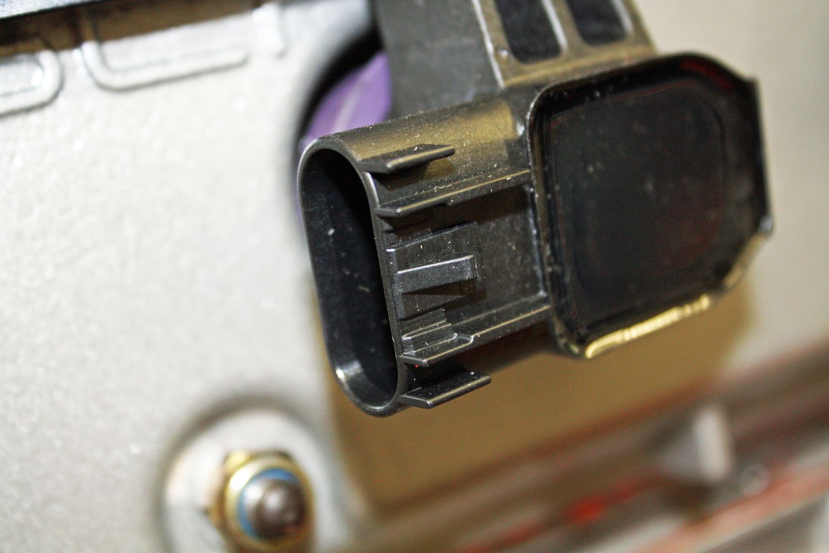
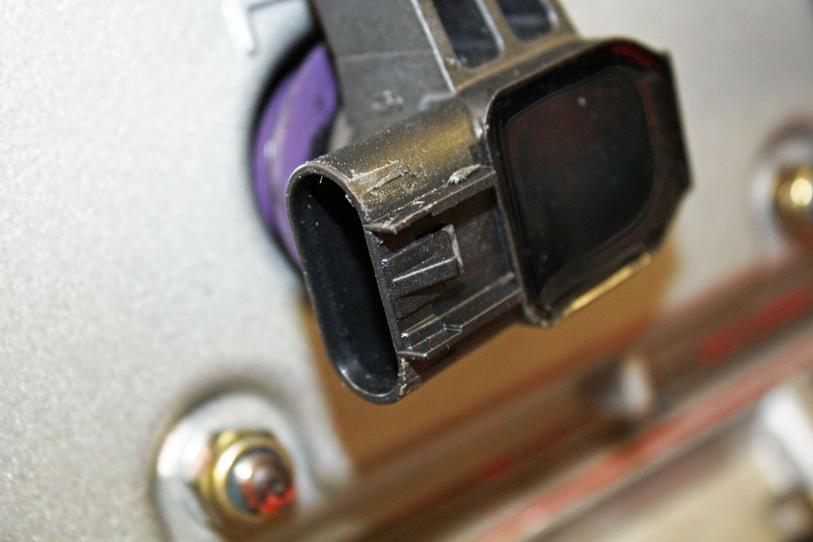
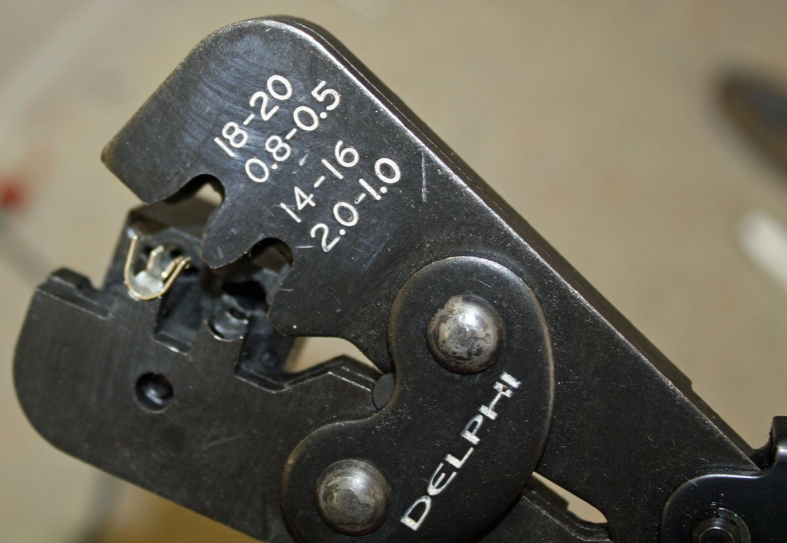
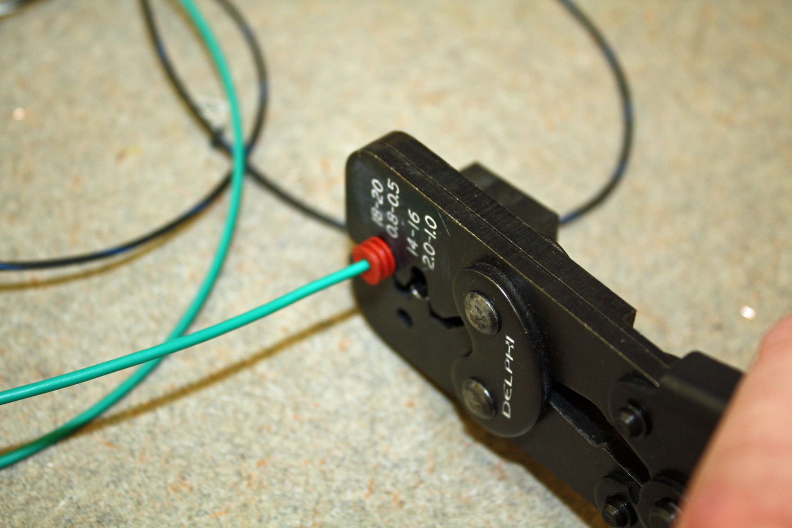
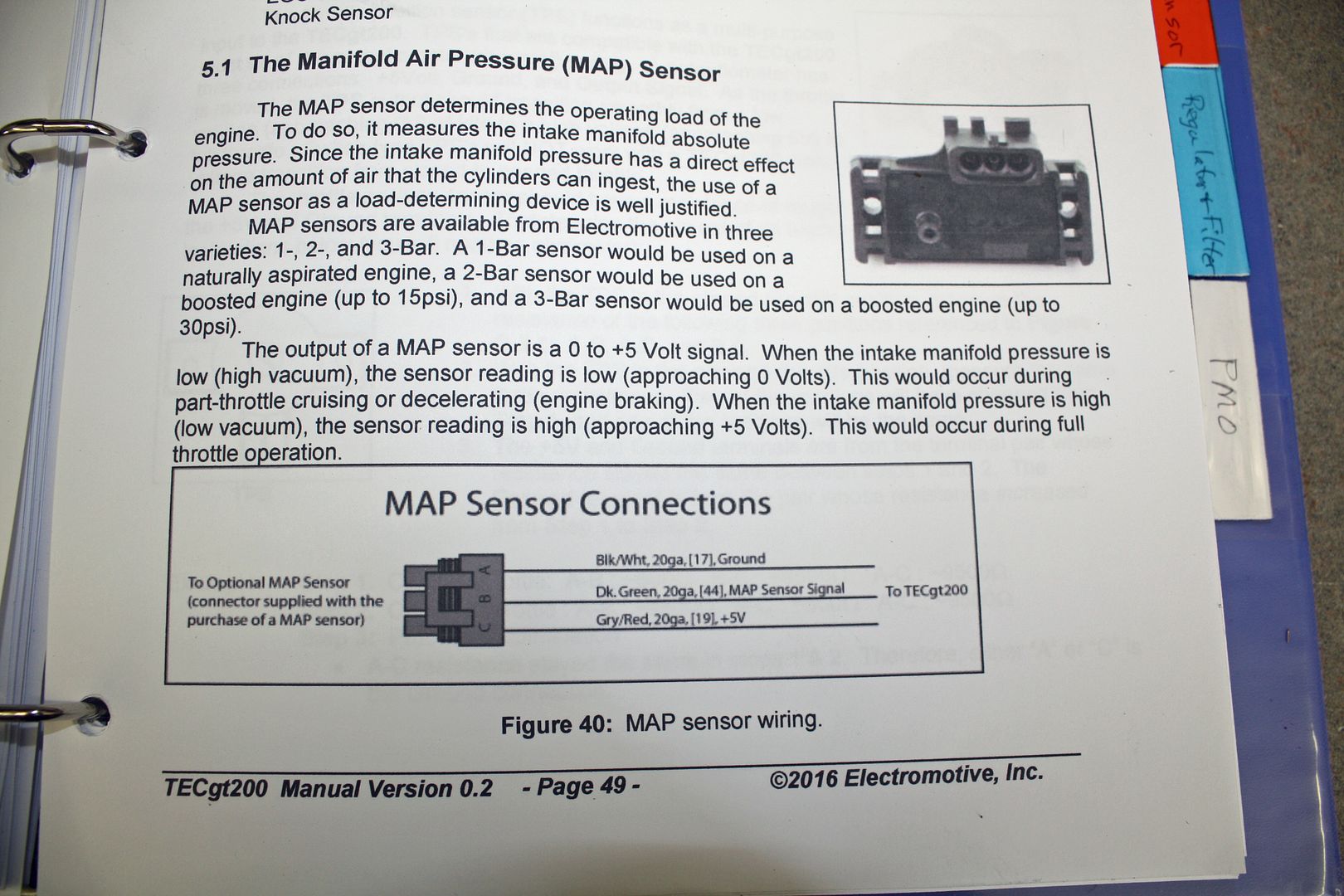
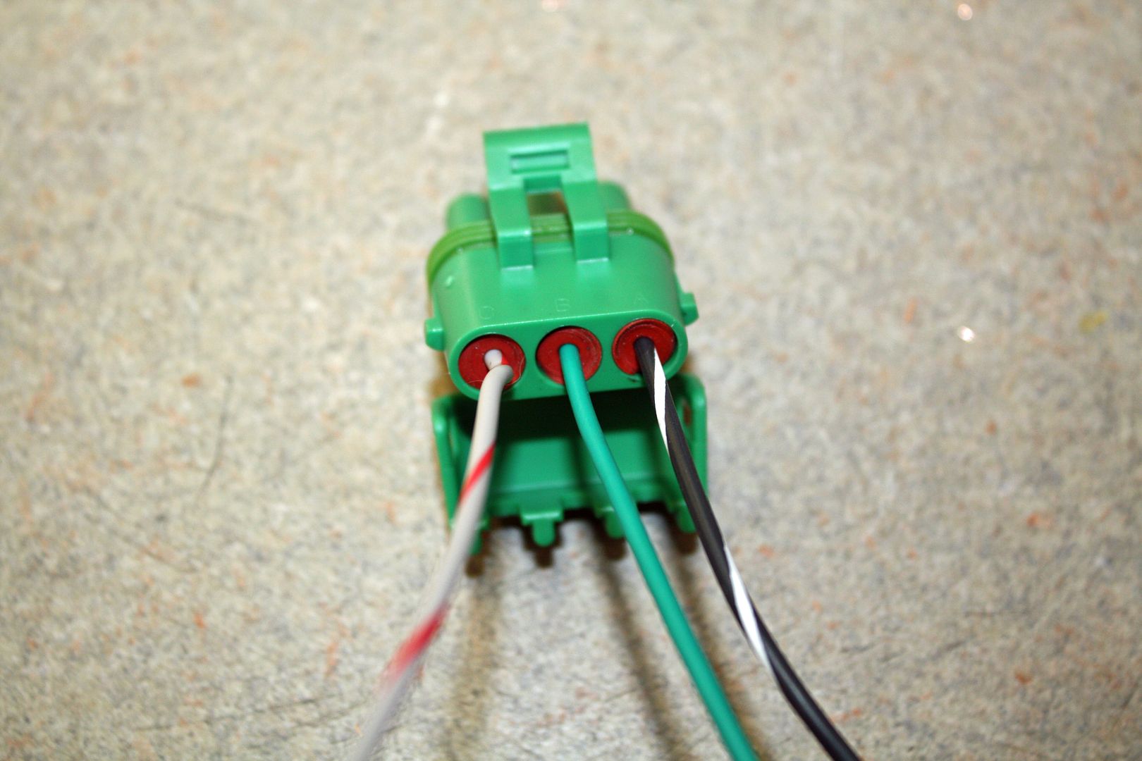
I was doing some studying on crimping when I came across someone saying that, for the weatherpack terminals, the OEM Delphi crimper works best. One advantage it has over the MSD crimper is that it has a guide for the terminals. You simply insert the terminal into the guide and it perfectly positions it. I ordered one and it came today. The MAP sensor is the first plug to use the weather pack terminals. The Delphi crimper made perfect crimps each time. It won't work with the other style of terminals. One advantage of the MSD crimper is that you can order different dies for different types of terminals. But they do not have one for metripack terminals. Now that I have it figured out, I can use the MSD tool with the weatherpack die to do the metripack terminals.
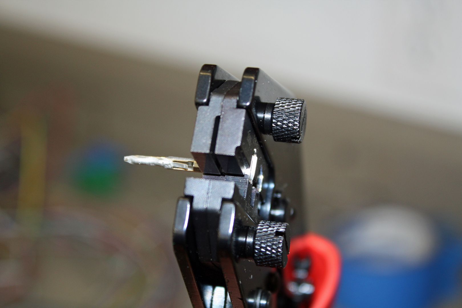
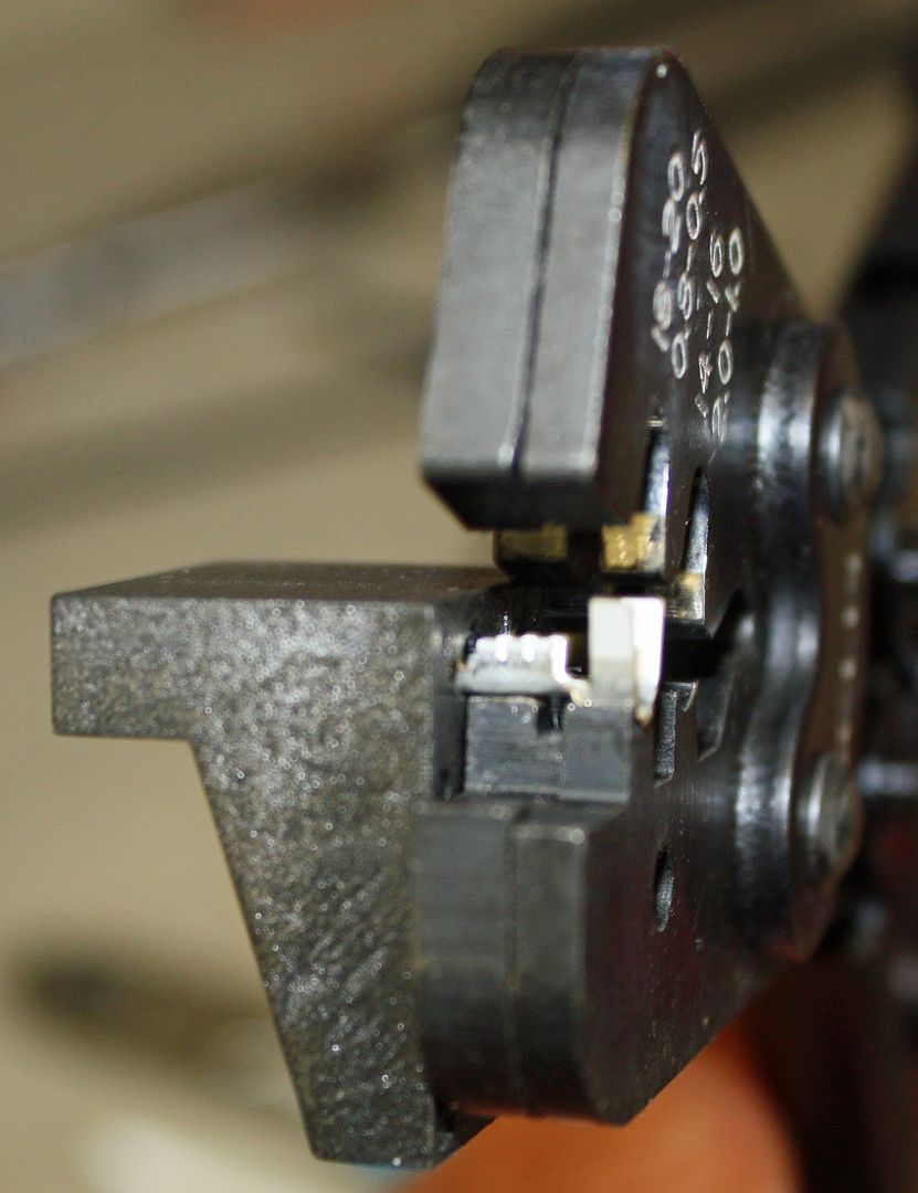
This is the MSD crimper with a terminal in place.
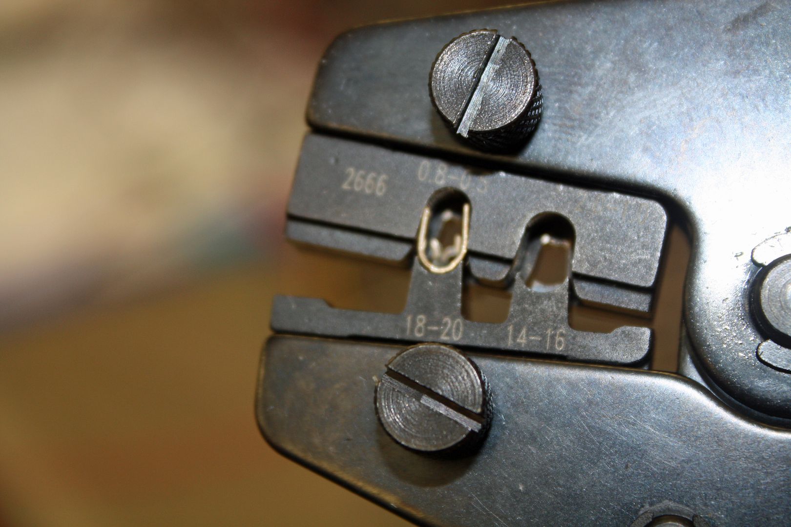
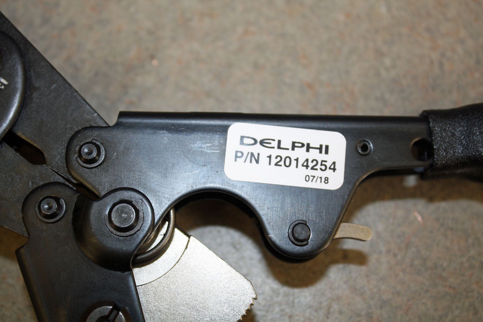
This is the Delphi crimper.
I was doing some studying on crimping when I came across someone saying that, for the weatherpack terminals, the OEM Delphi crimper works best. One advantage it has over the MSD crimper is that it has a guide for the terminals. You simply insert the terminal into the guide and it perfectly positions it. I ordered one and it came today. The MAP sensor is the first plug to use the weather pack terminals. The Delphi crimper made perfect crimps each time. It won't work with the other style of terminals. One advantage of the MSD crimper is that you can order different dies for different types of terminals. But they do not have one for metripack terminals. Now that I have it figured out, I can use the MSD tool with the weatherpack die to do the metripack terminals.
This is the MSD crimper with a terminal in place.


This is the Delphi crimper.


 10-04-2018, 05:49 PM
#65
Racer
Thread Starter
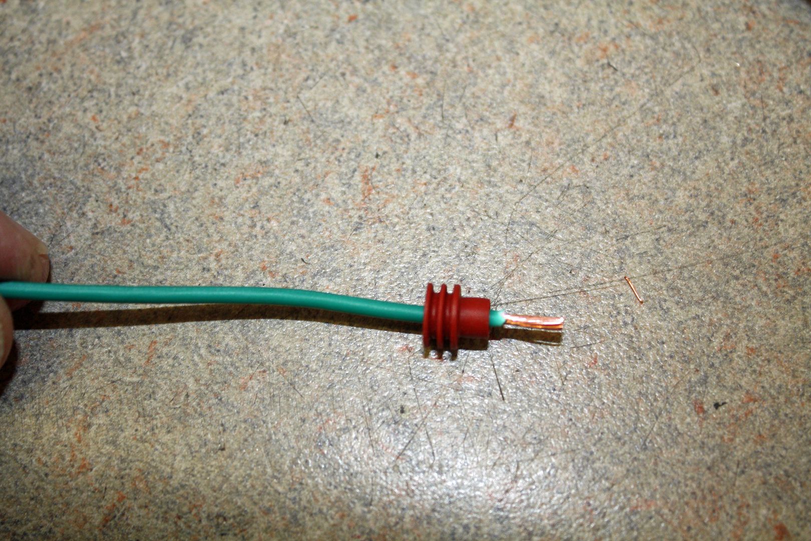
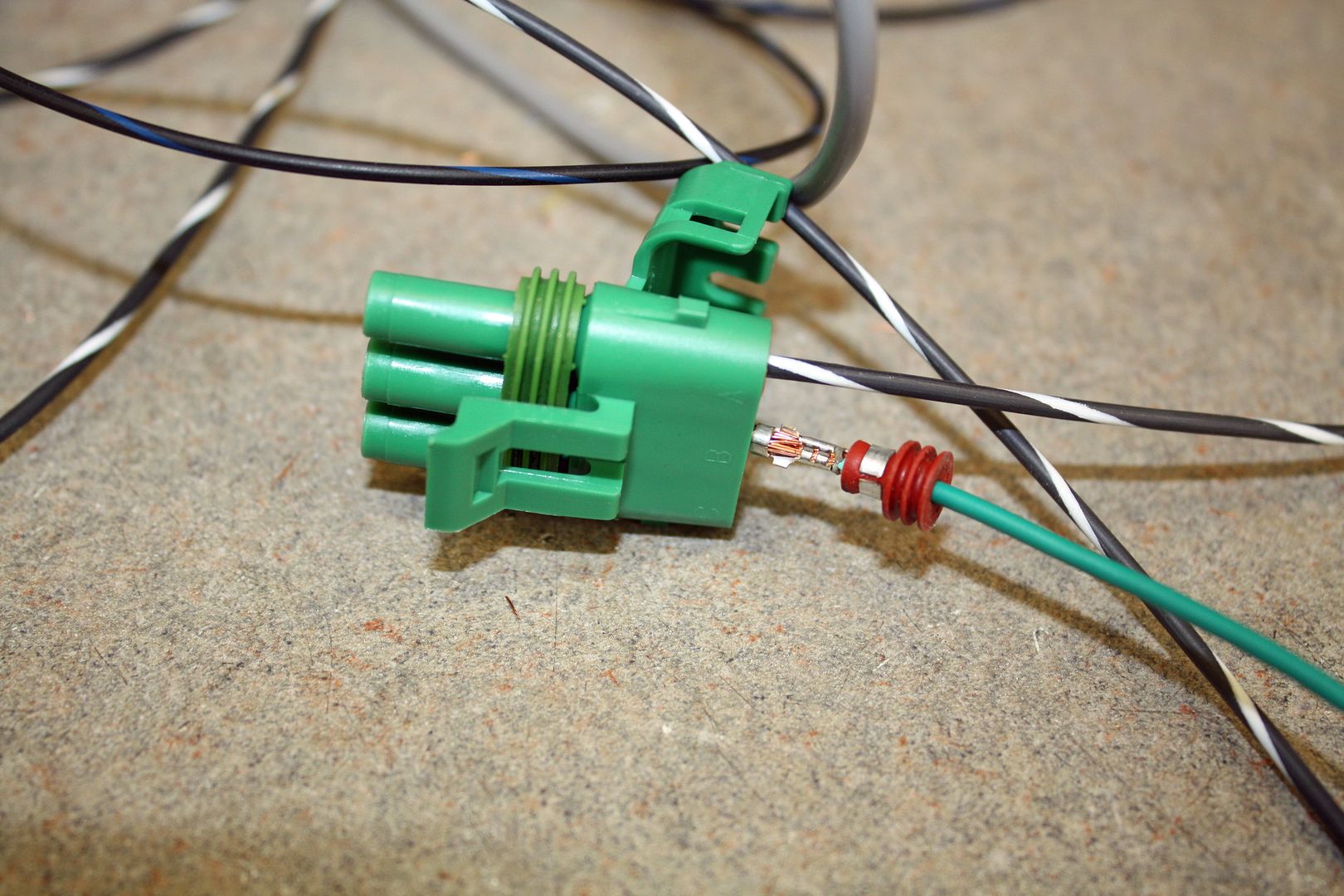
With the new crimper, it did not take long to do the three wires for the MAP plug.
I also spent some time pulling each wire that i have used so far out of the harness, cutting it to a length that will go from the ECU to the bulkhead plug that I will be using and labeling them. I then inserted each plug in place and tidied bunched up the wires in preparation for the final running of the wires.
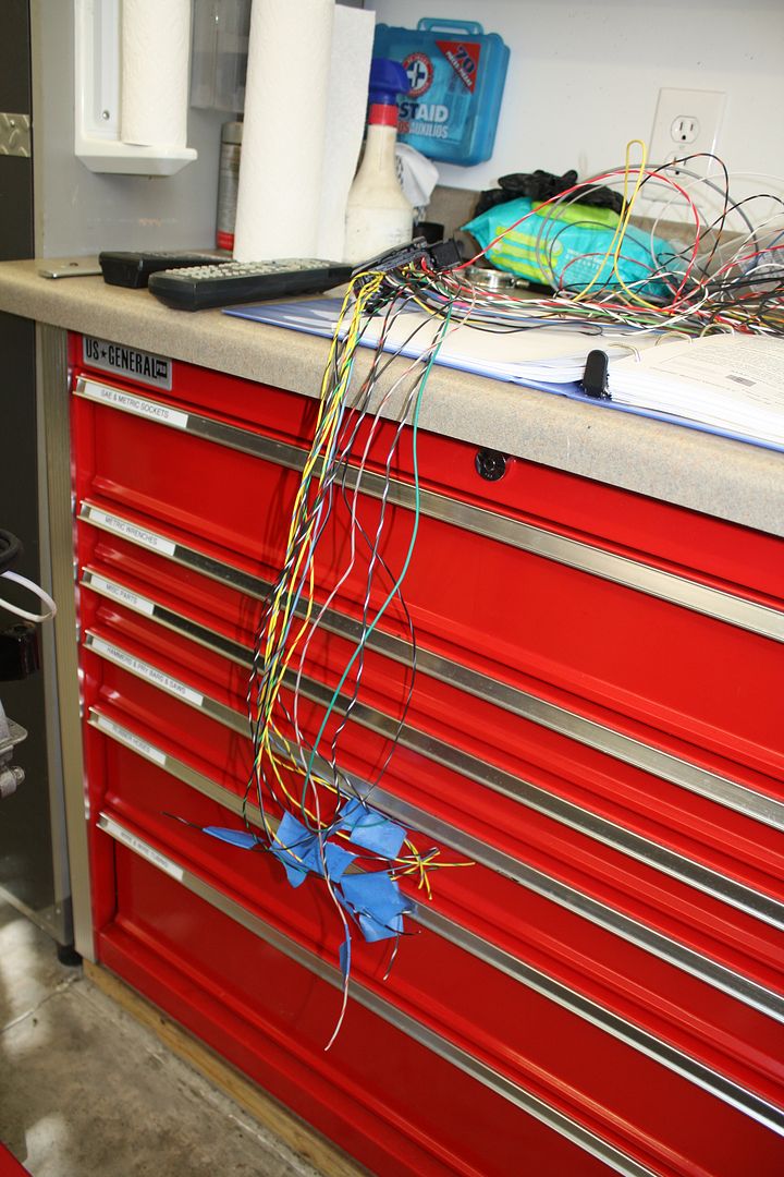


I also spent some time pulling each wire that i have used so far out of the harness, cutting it to a length that will go from the ECU to the bulkhead plug that I will be using and labeling them. I then inserted each plug in place and tidied bunched up the wires in preparation for the final running of the wires.


 10-08-2018, 05:45 PM
#67
Racer
Thread Starter
Usually my project cars move along a bit faster than this one. Other things that have to be done keep popping up. Such is life.
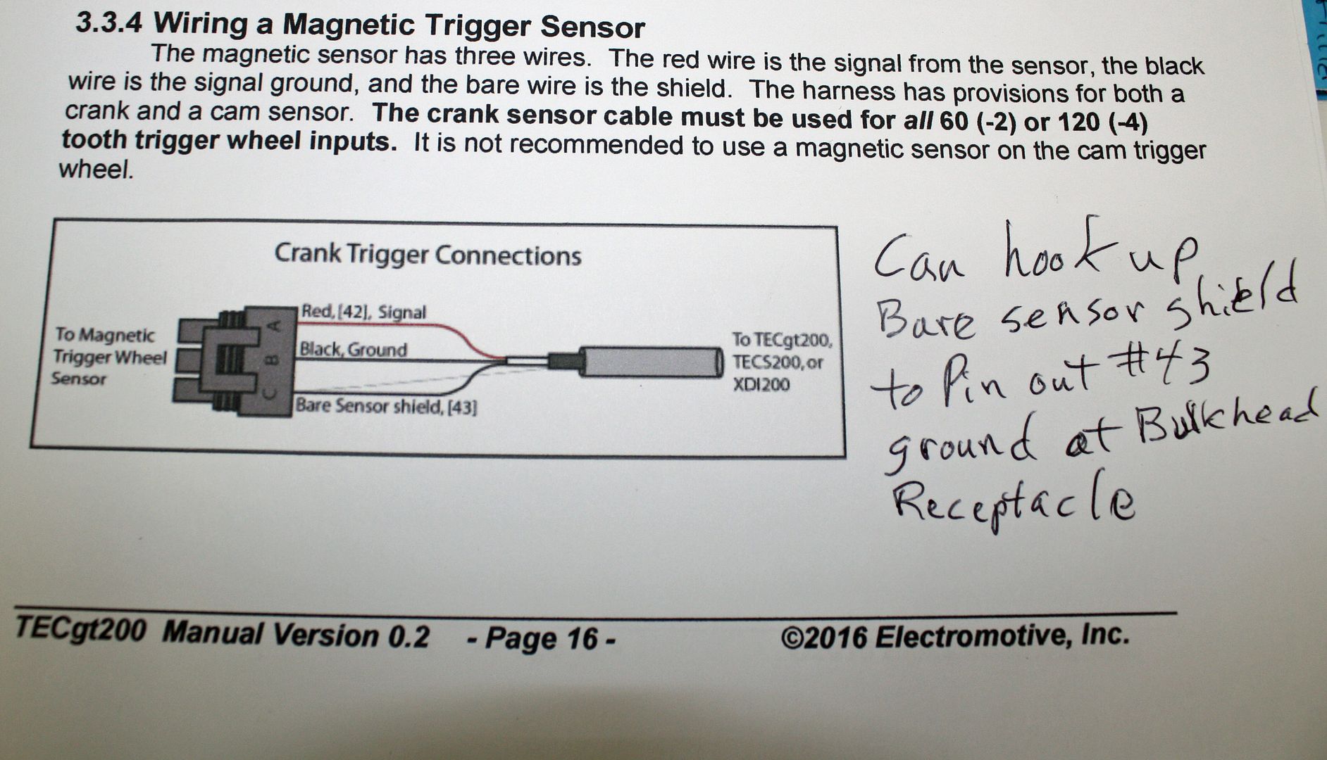
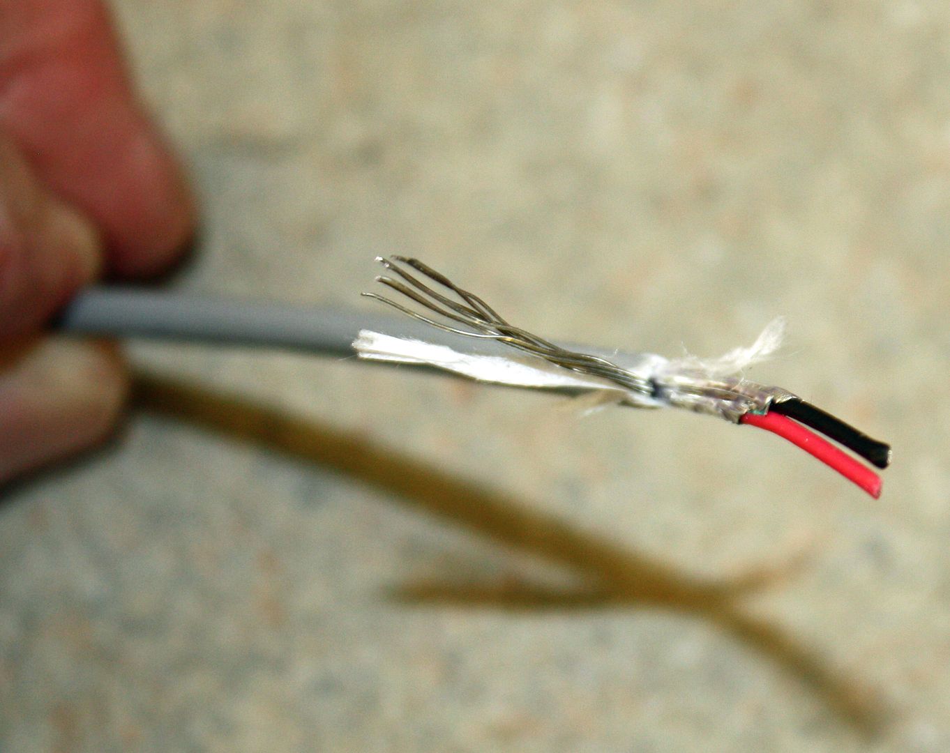
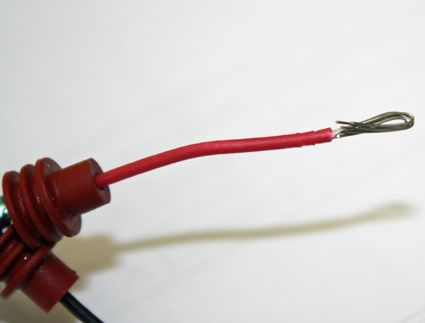
More wiring was completed today. The crank trigger cable is shielded and contains a red, black and bare wire. These are very small wires so I doubled up the stripped wire to have more wire to crimp to.
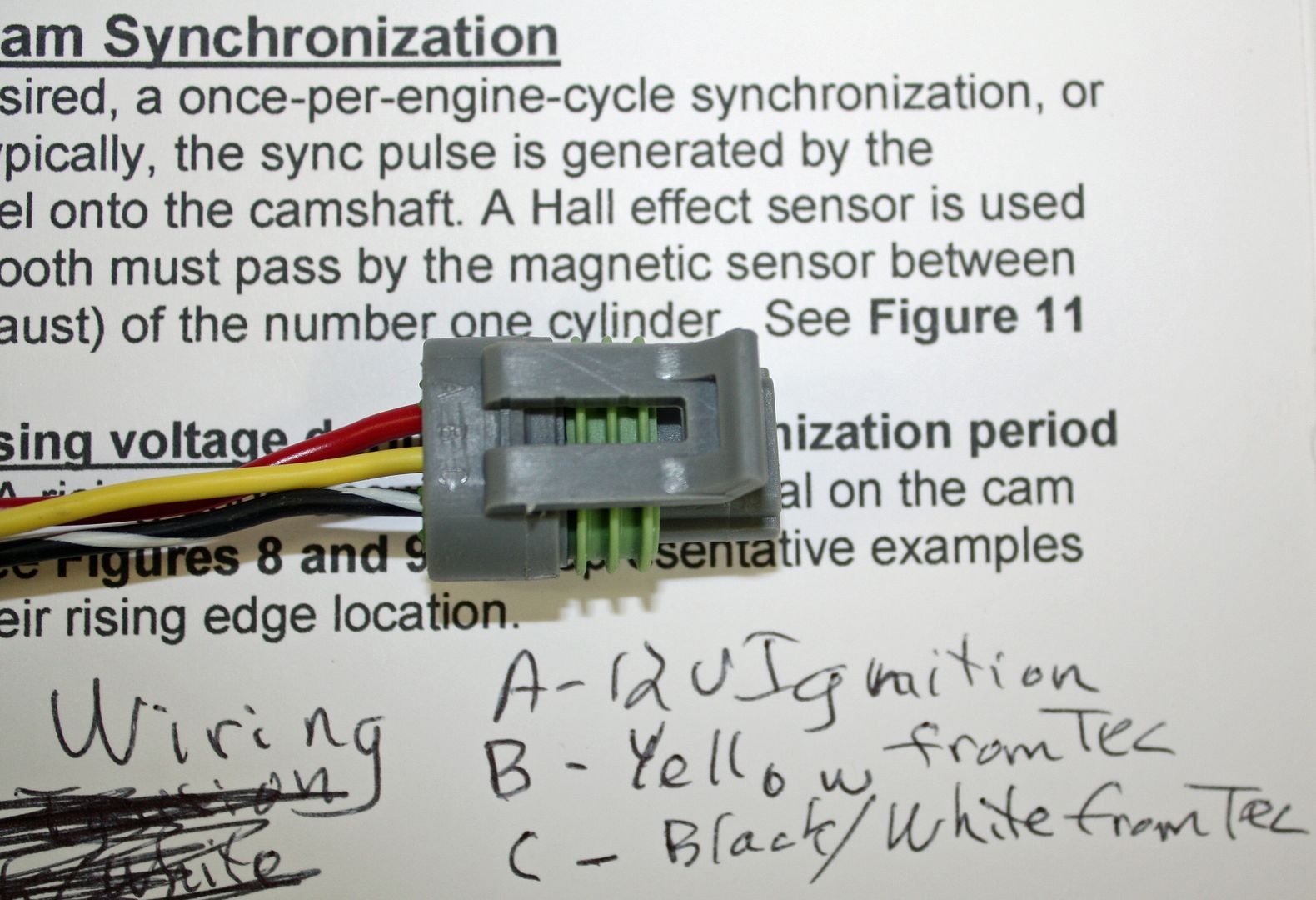
The cam sensor wiring was next.
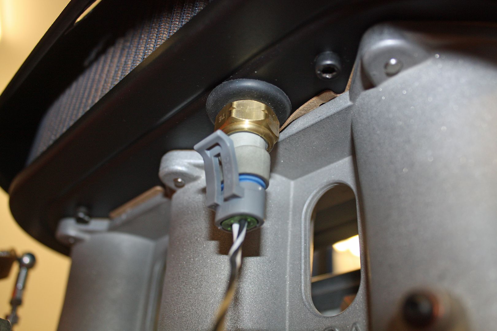
Next up was the head temp sensor.
And then came the air temp sensor.

More wiring was completed today. The crank trigger cable is shielded and contains a red, black and bare wire. These are very small wires so I doubled up the stripped wire to have more wire to crimp to.


The cam sensor wiring was next.


Next up was the head temp sensor.

And then came the air temp sensor.

 10-09-2018, 05:24 PM
#68
Racer
Thread Starter
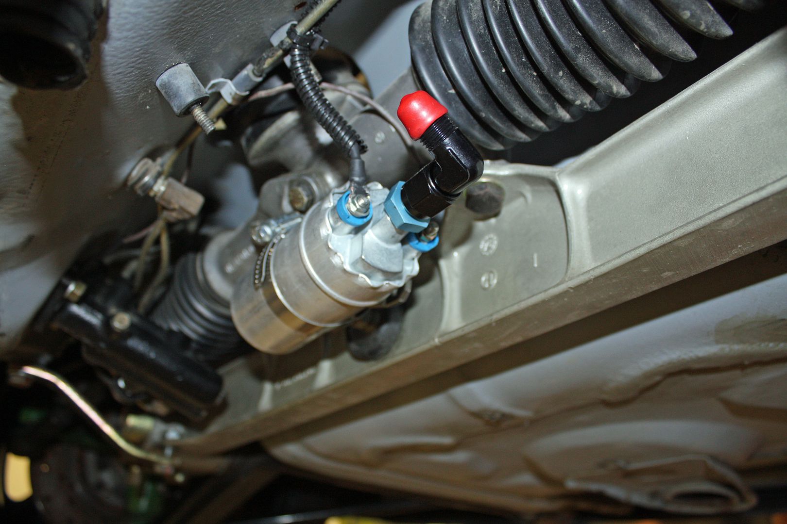
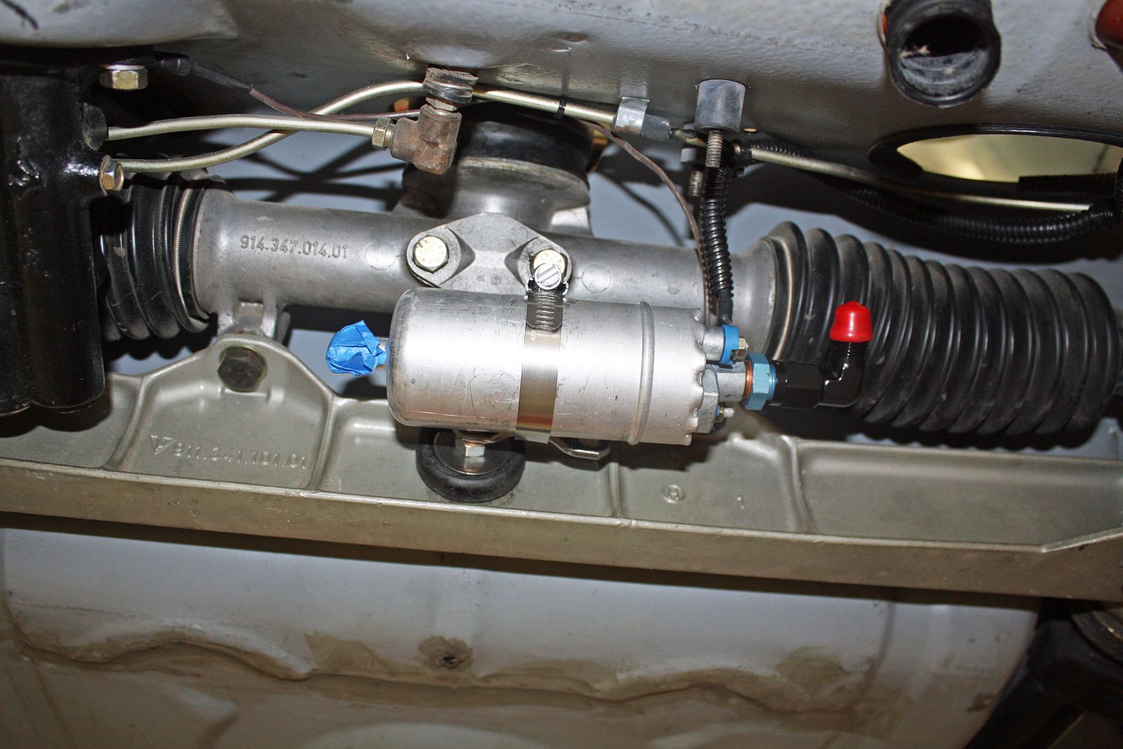
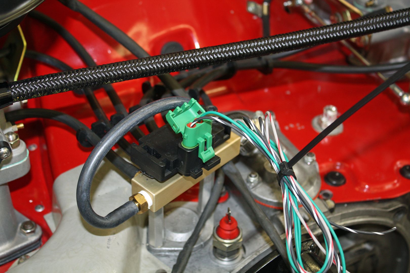
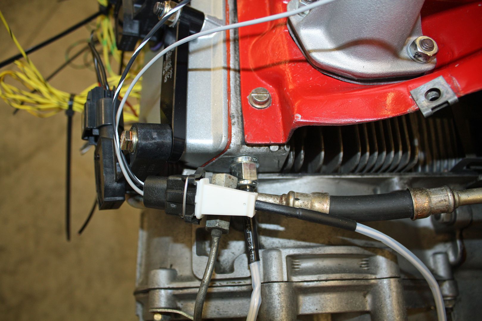
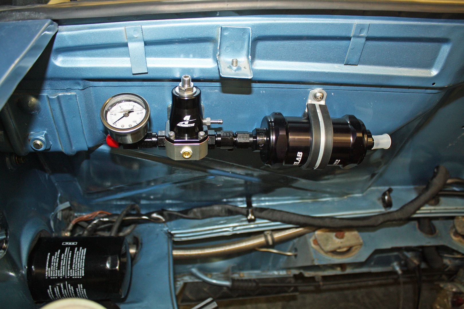
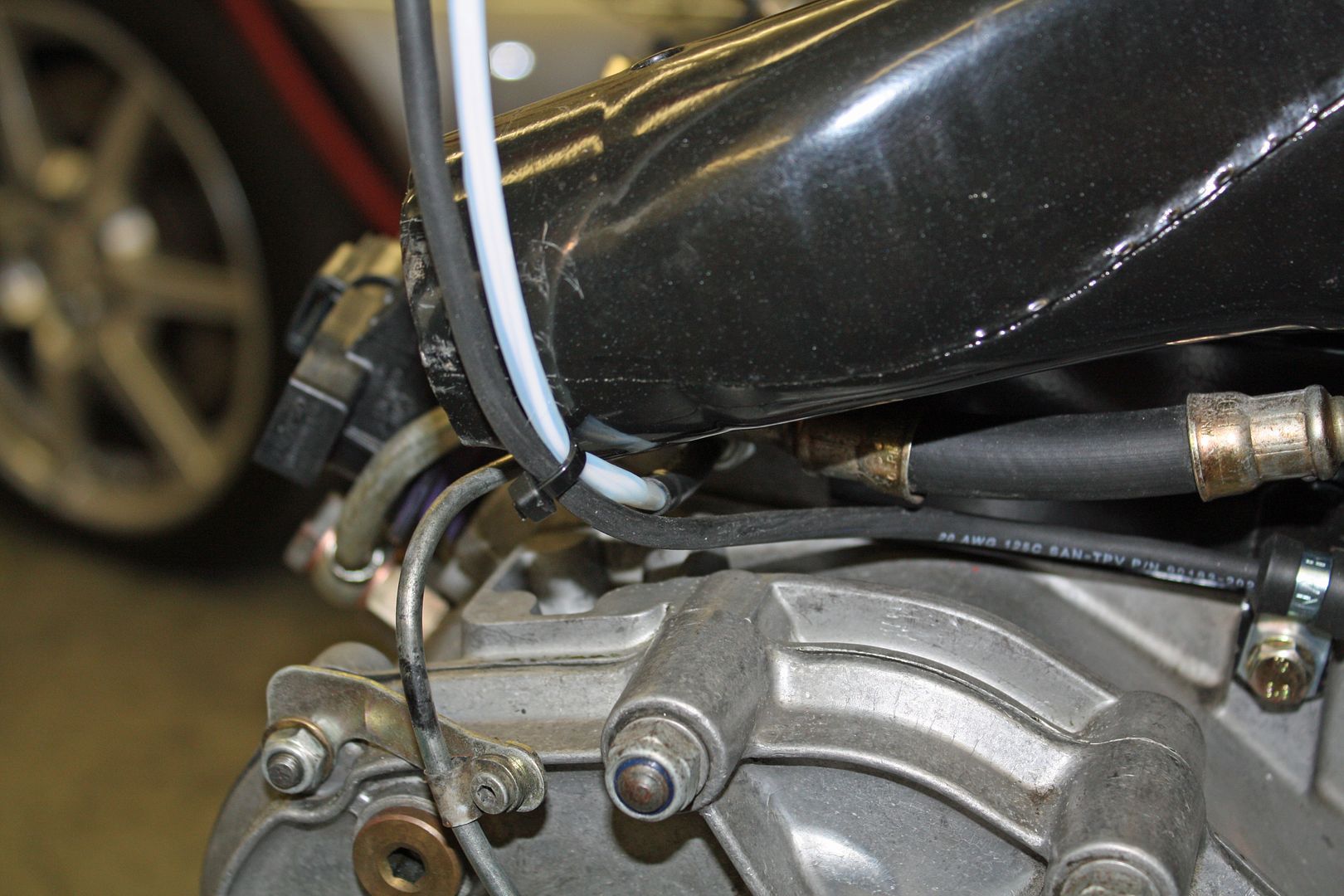
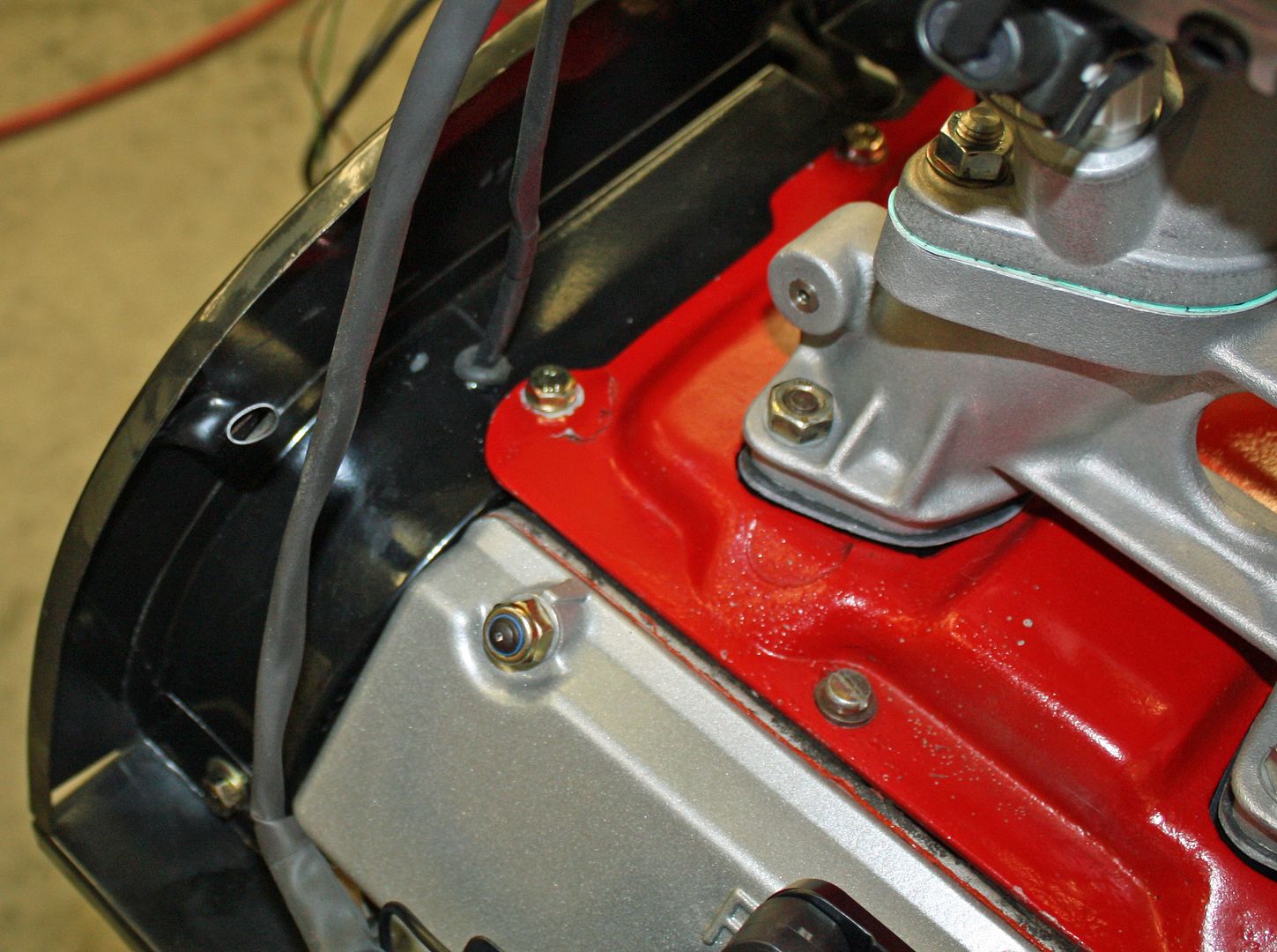
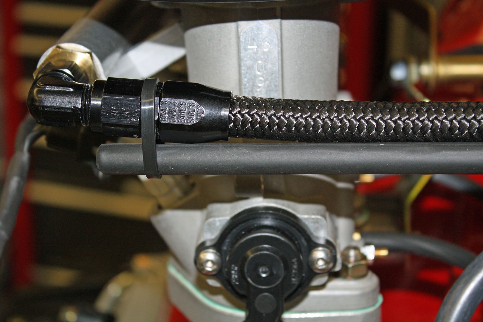
One night last week when I couldn't go back to sleep, I began thinking about the fuel pressure gauge. I had initially installed it on the fuel line at the rear of the throttle bodies. That was before I installed the fuel pressure regulator and the filter on the firewall. It came to me that it would be better to have the gauge installed there as it would be easier to read and would not be subject to engine vibration. So, today, I moved it and then made a new line to connect the throttle bodies.
I spent the rest of the day finishing up the wiring on the left side. On the COP's, each one is individually grounded to the motor. I used one of the valve cover studs for that ground. The black/white wire and the red wire go to all of the COP's. I had to tap into the main red and black/white line at each unit. I also ran the wiring for the crank fire and the head temp sensor.
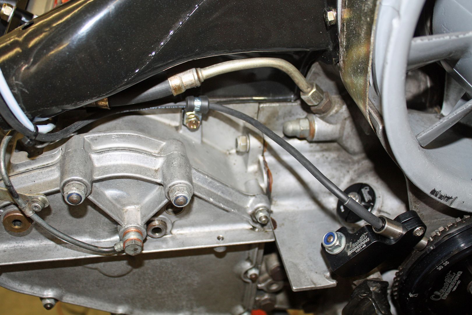
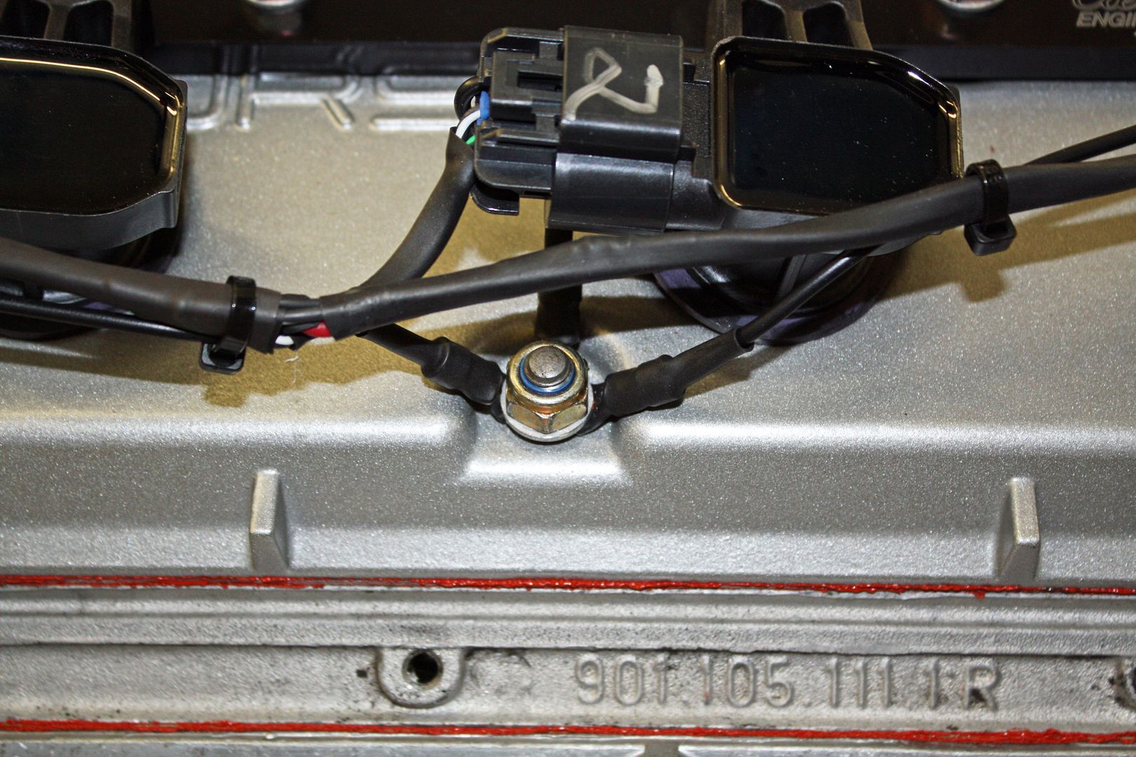


I spent the rest of the day finishing up the wiring on the left side. On the COP's, each one is individually grounded to the motor. I used one of the valve cover studs for that ground. The black/white wire and the red wire go to all of the COP's. I had to tap into the main red and black/white line at each unit. I also ran the wiring for the crank fire and the head temp sensor.


 10-10-2018, 05:44 PM
#70
Racer
Thread Starter
You're welcome. While videos about a project are very helpful, I find good photos with a good description to be better. So hopefully these photos help someone in the future.
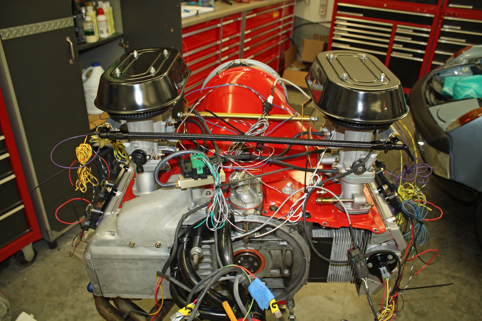
Between taking the dog to the groomer and picking her up, I got the right side done as well as beginning to run everything to the center. It is very time consuming figuring out what part of the wiring to apply the shrink tubing to, soldering the wire connections, installing the next pieces of shrink tubing, and then moving on to the next one.
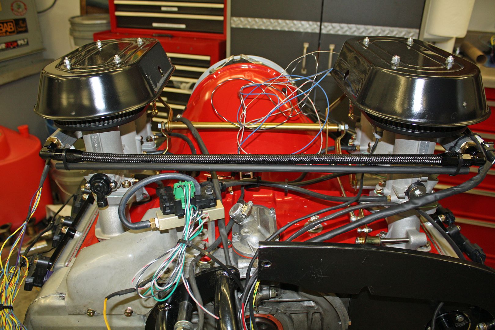
I like running the wiring along the fuel line to keep everything away from the throttle linkage, but I am concerned about putting too much weight on the line. I think I will find a rod of some type to run between the two sides, attach the rod at each end and then attach the harness to that rod. From the center of that fuel line, I plan on taking all the wires up to a bulkhead connector.
Between taking the dog to the groomer and picking her up, I got the right side done as well as beginning to run everything to the center. It is very time consuming figuring out what part of the wiring to apply the shrink tubing to, soldering the wire connections, installing the next pieces of shrink tubing, and then moving on to the next one.
I like running the wiring along the fuel line to keep everything away from the throttle linkage, but I am concerned about putting too much weight on the line. I think I will find a rod of some type to run between the two sides, attach the rod at each end and then attach the harness to that rod. From the center of that fuel line, I plan on taking all the wires up to a bulkhead connector.

 10-11-2018, 05:19 PM
#71
Racer
Thread Starter
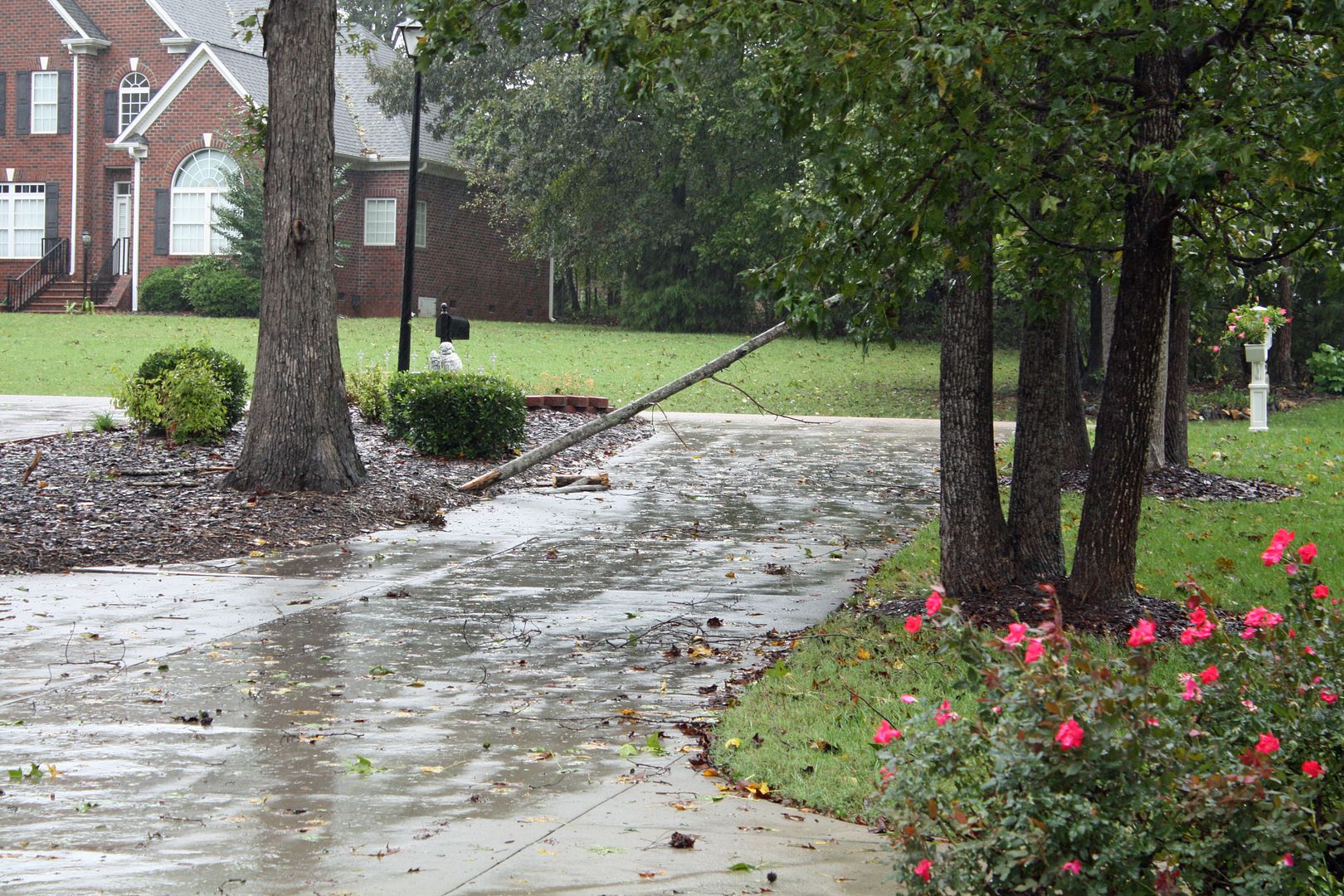
We had more wind today than during the previous hurricane. I had to remove this limb so my wife can get into the driveway. We had quite a bit of rain but everything passed through quickly.
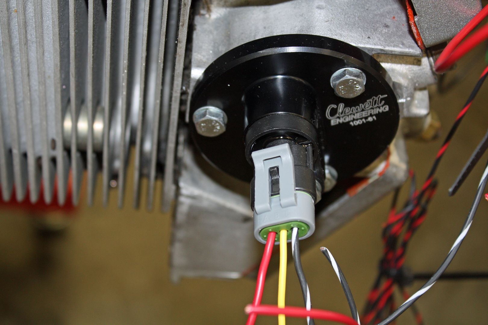
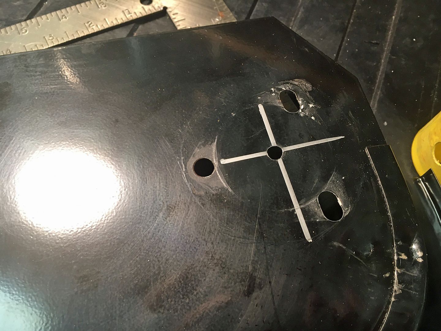
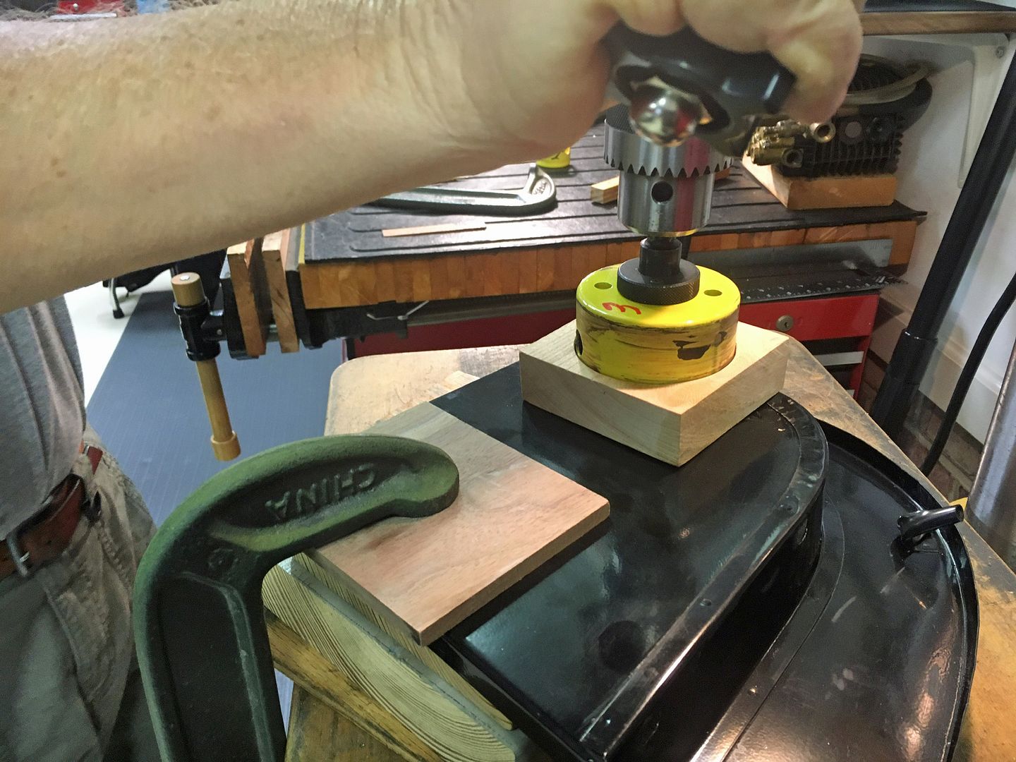
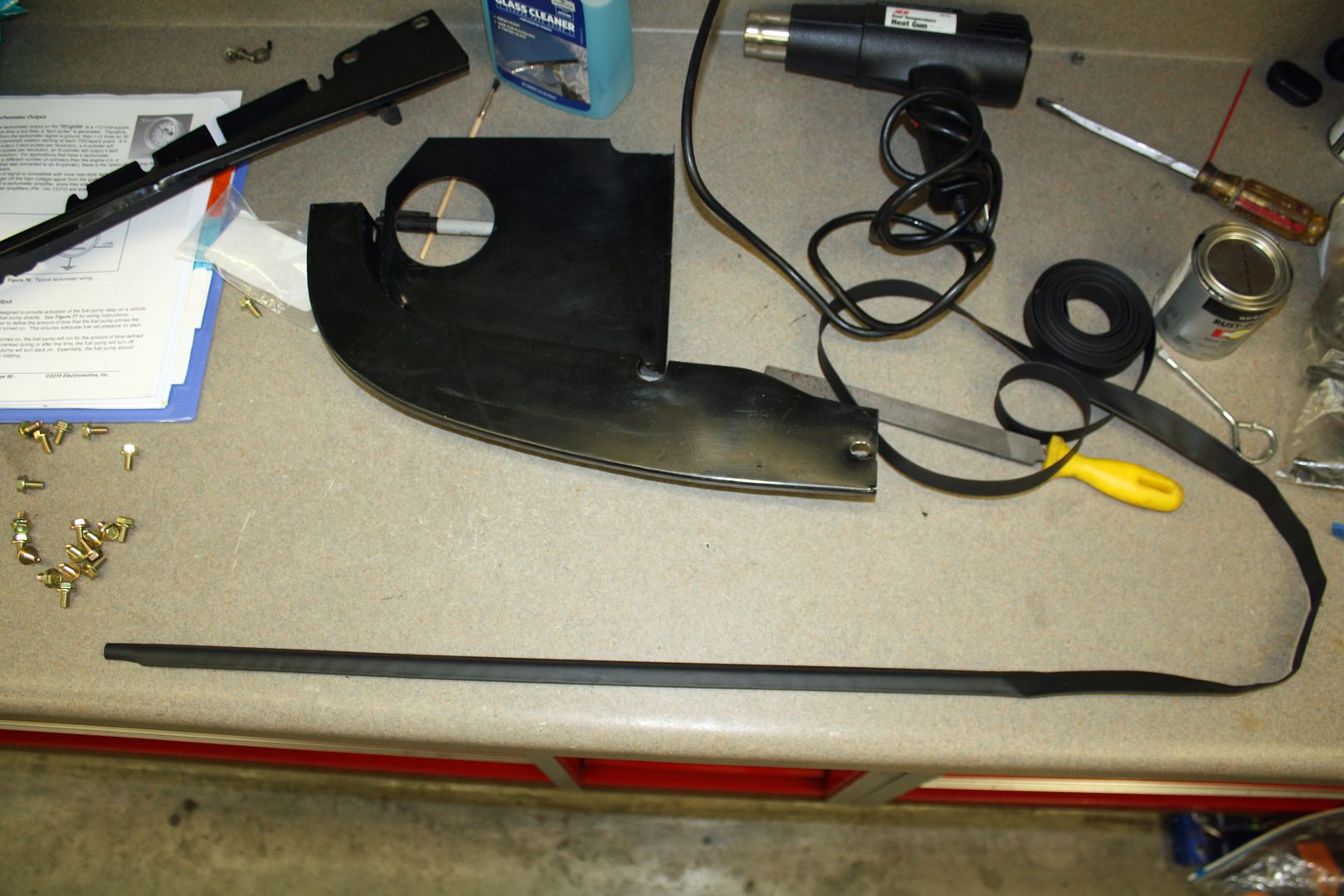
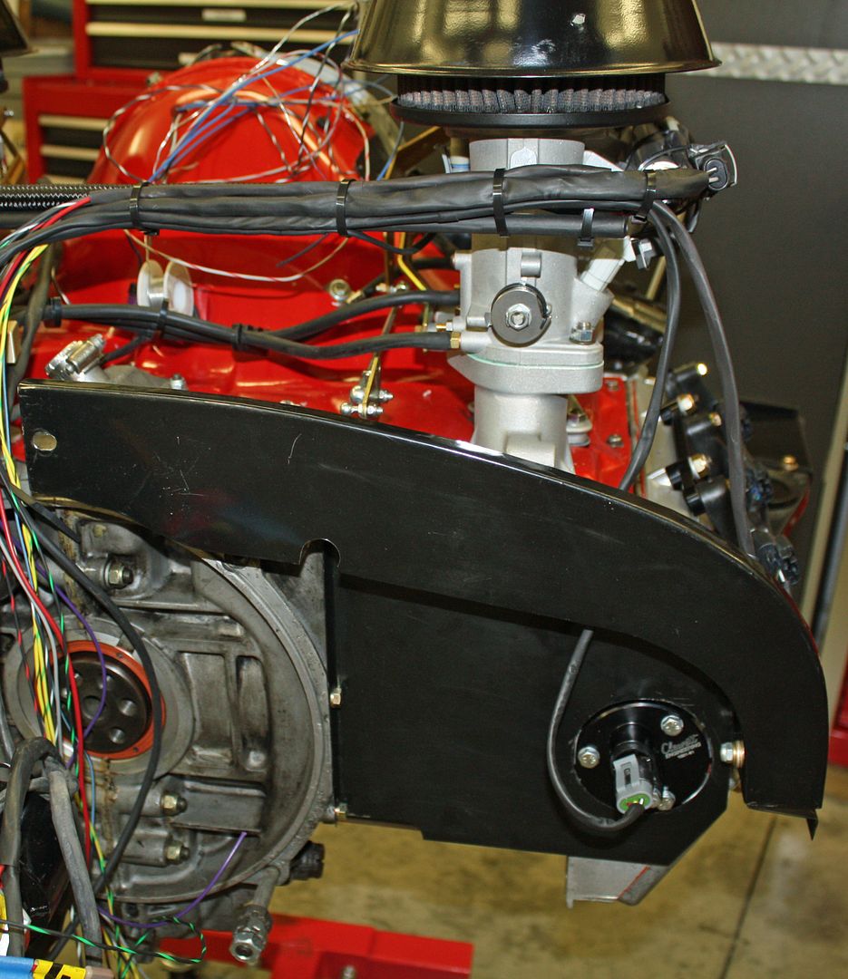
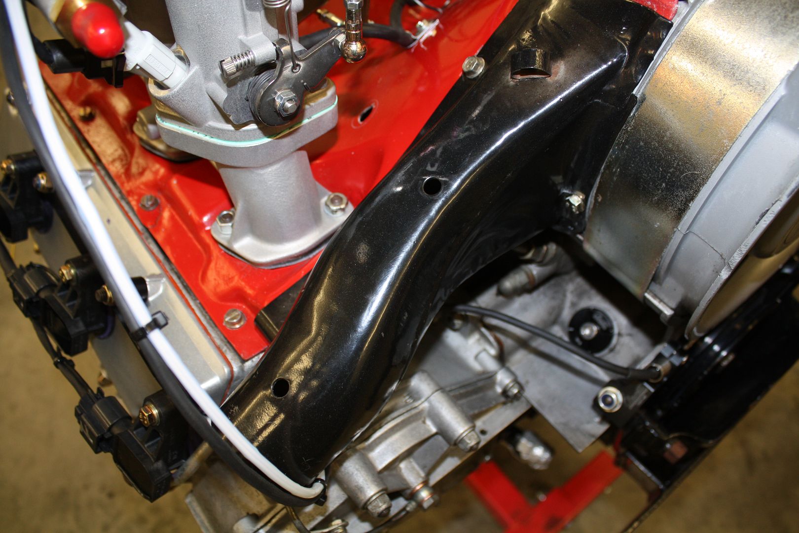
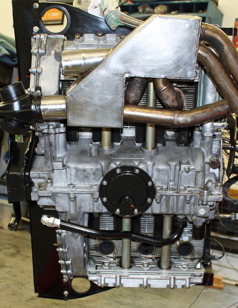
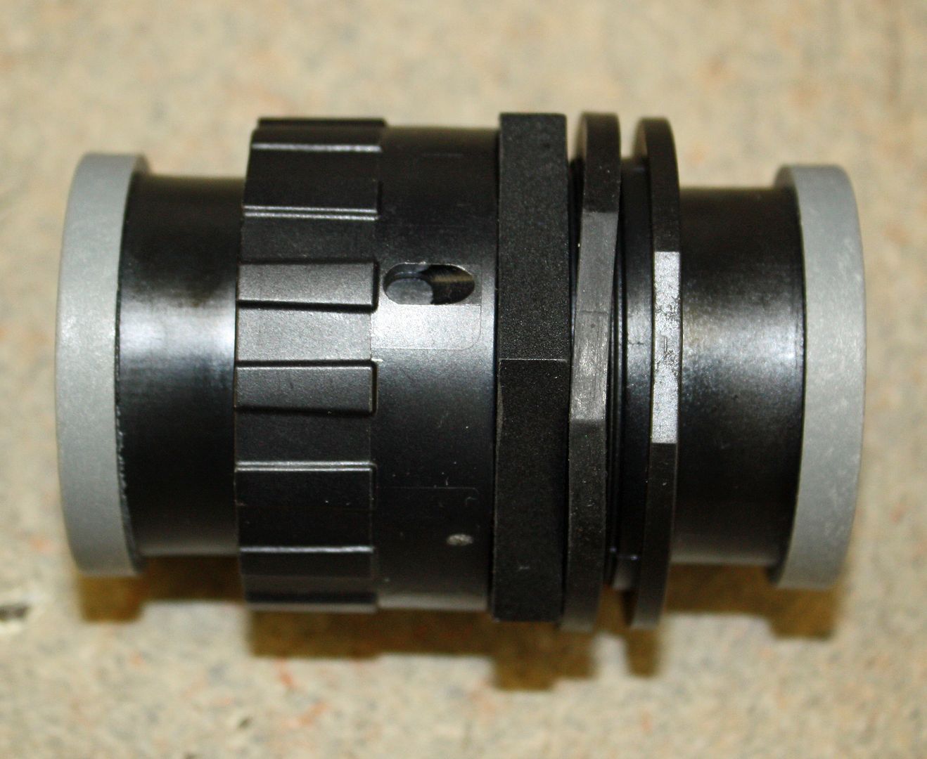
Yesterday I realized that I had to modify the engine tin around the cam sync adapter. Normally the engine tin here fits flush against the back of the block and there is a seal between the tin and the cam carrier. After measuring the diameter of the cam sync adapter, I needed to drill a three inch hole. I didn't have a hole saw that large but my buddy and neighbor did have one. He has every tool known to mankind!! I took the tin to him to show him what I needed to do. He took pity on me and proceeded to drill the hole in his garage. BTW, compared to his garage, my garage is filthy!!! After getting back to my garage, I drilled a hole and installed a grommet for the cam sync adapter harness.
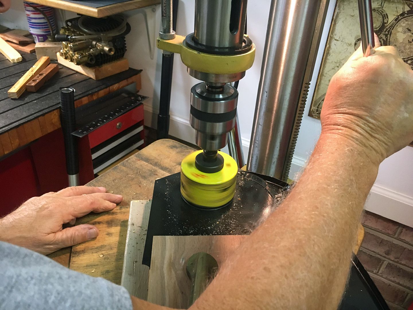
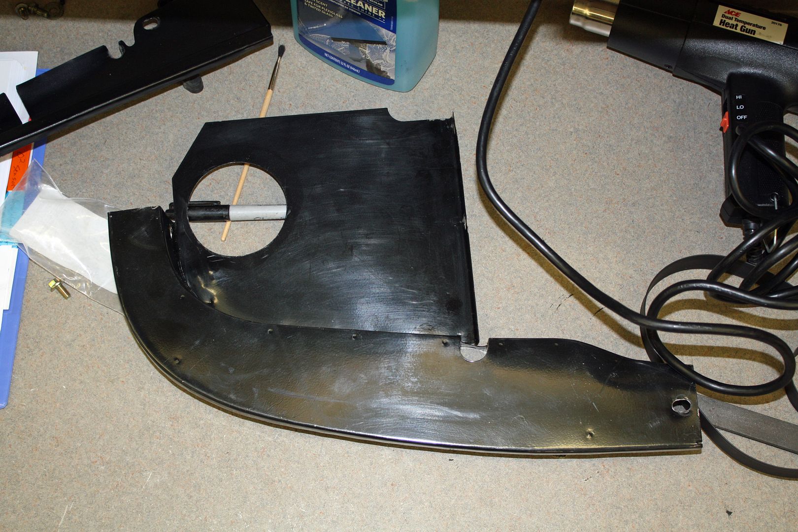
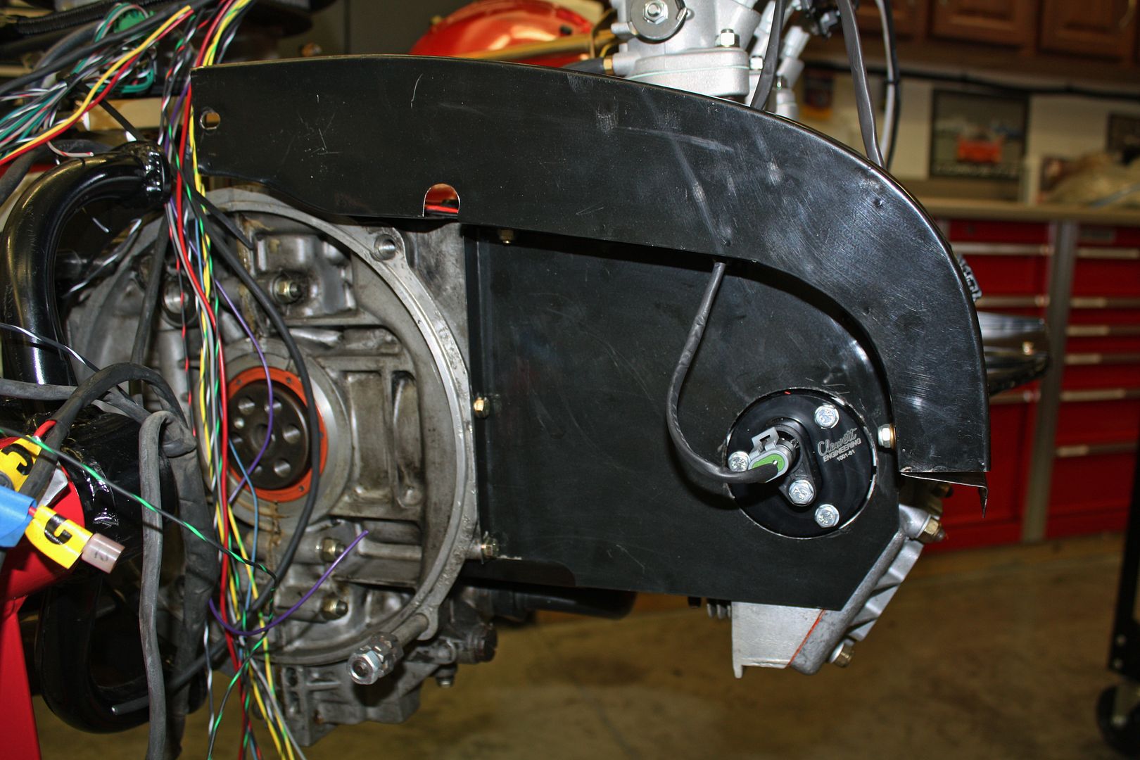
I also installed the rest of the engine tin except for the piece on the right rear. I can't install it until i remove the engine from the engine stand.

Yesterday I realized that I had to modify the engine tin around the cam sync adapter. Normally the engine tin here fits flush against the back of the block and there is a seal between the tin and the cam carrier. After measuring the diameter of the cam sync adapter, I needed to drill a three inch hole. I didn't have a hole saw that large but my buddy and neighbor did have one. He has every tool known to mankind!! I took the tin to him to show him what I needed to do. He took pity on me and proceeded to drill the hole in his garage. BTW, compared to his garage, my garage is filthy!!! After getting back to my garage, I drilled a hole and installed a grommet for the cam sync adapter harness.


I also installed the rest of the engine tin except for the piece on the right rear. I can't install it until i remove the engine from the engine stand.

 10-11-2018, 05:47 PM
#72
Racer
Thread Starter
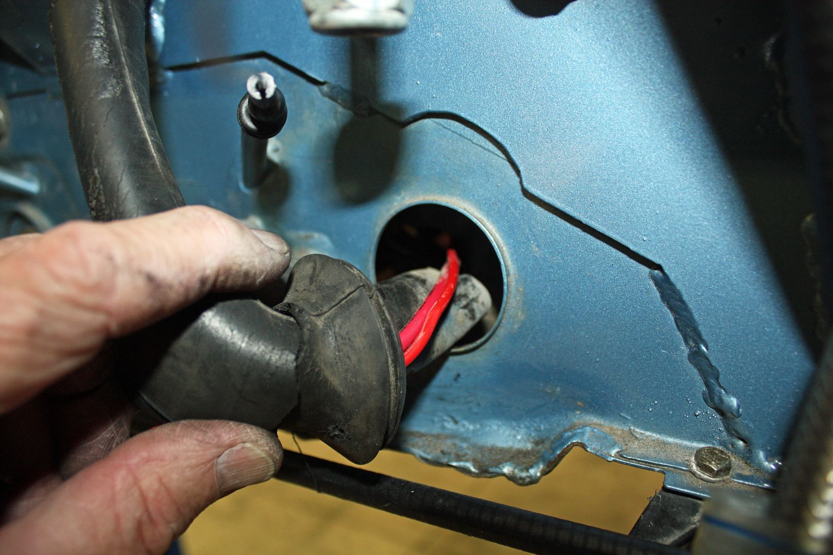
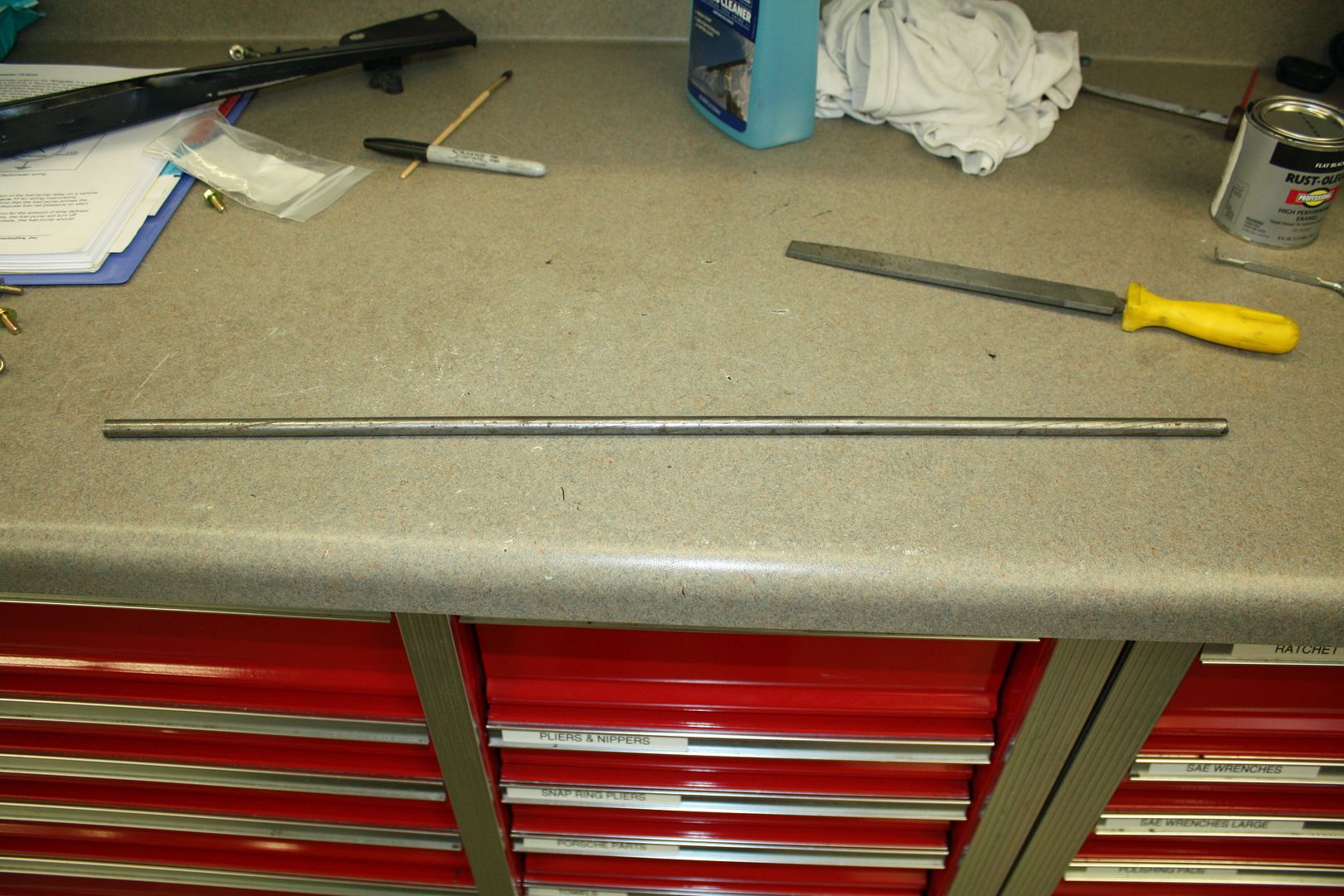
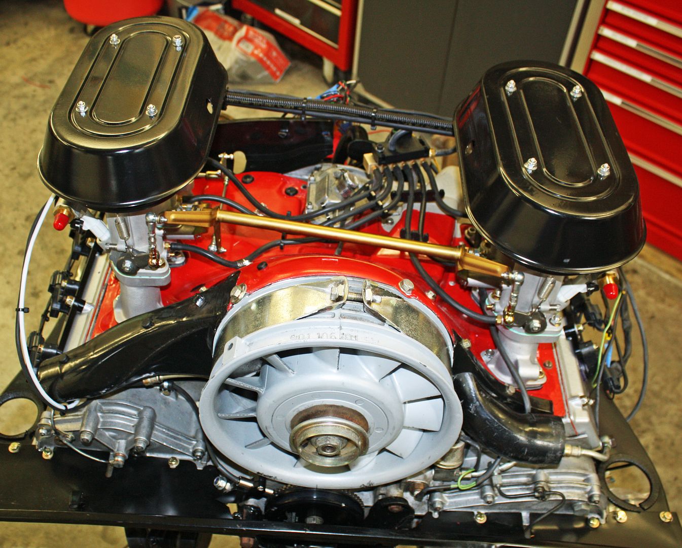
As I mentioned yesterday, I felt I needed to install a rod of some kind along the fuel line for support. A quick rummage through my metal bin turned up a 1/4" rod. After cutting it to length, I covered it with 1/2" shrink tube so it would blend in and to reduce chafing.
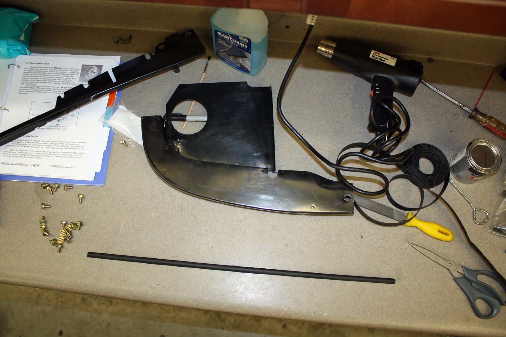
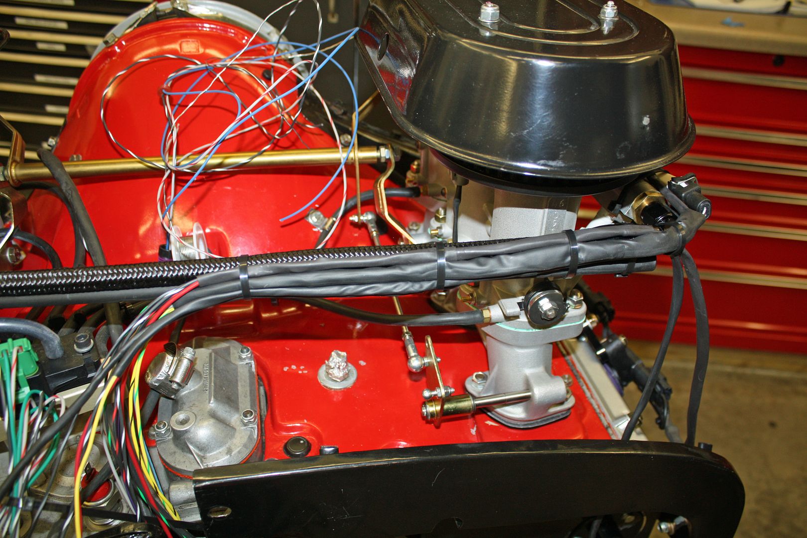
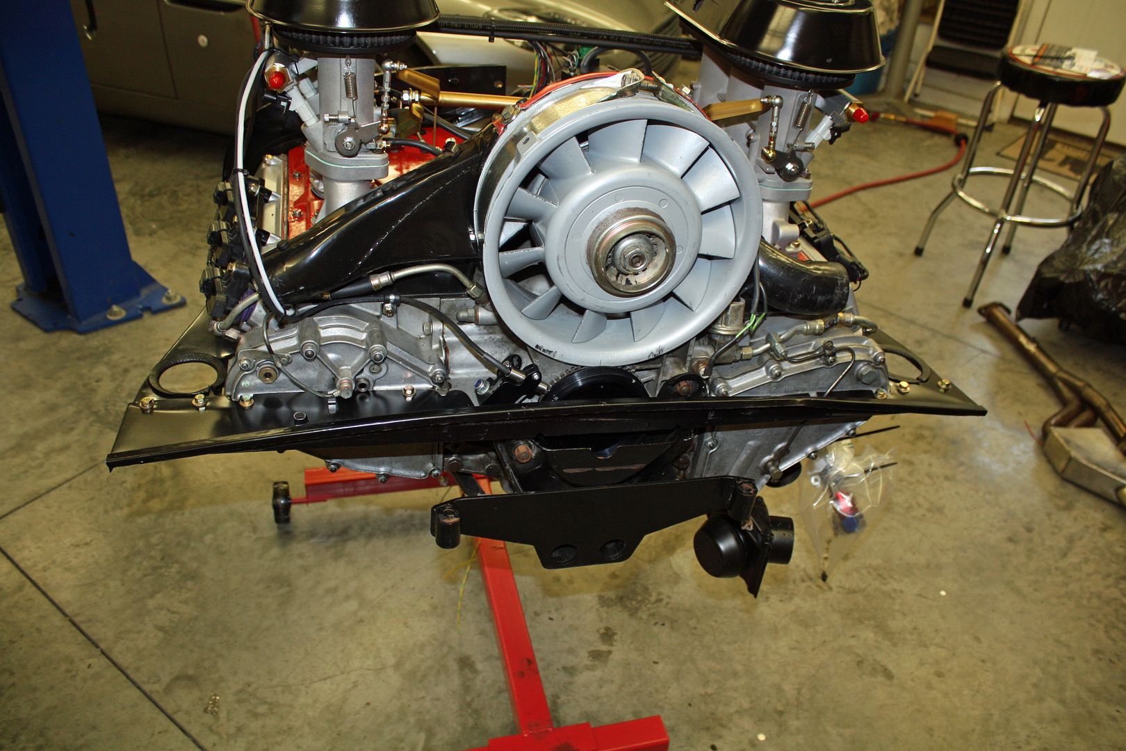
Since I won't have any spark plug wires, I inserted rubber plugs in the holes in the tin and the fan shroud.
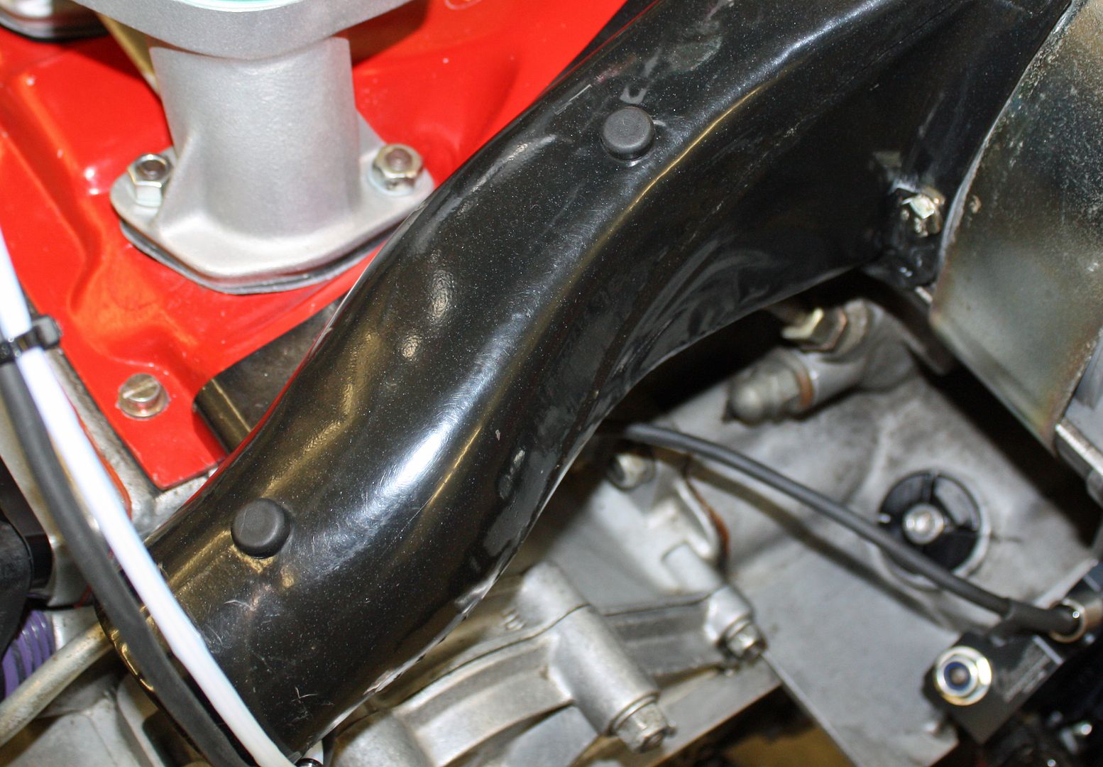
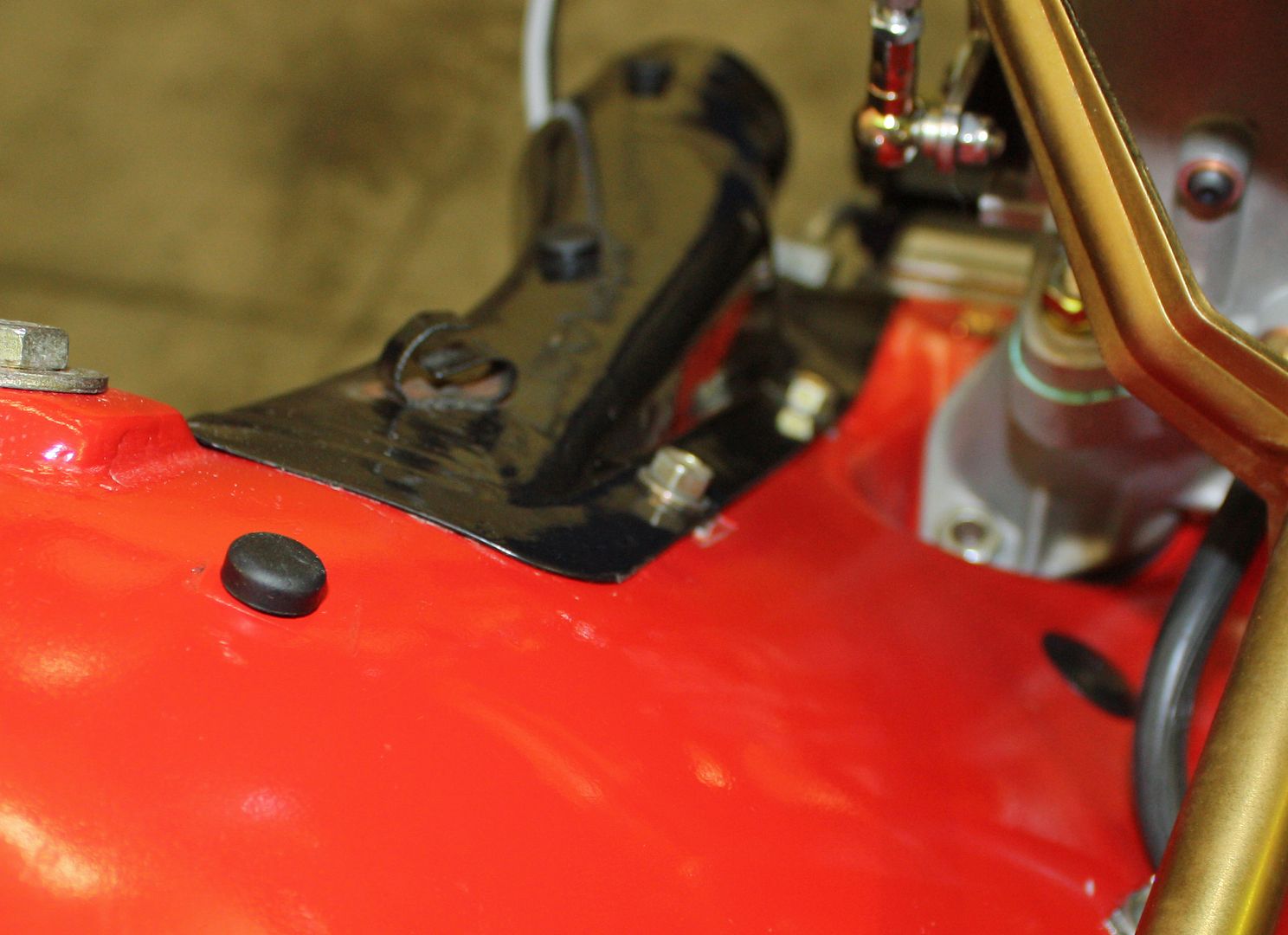


Since I won't have any spark plug wires, I inserted rubber plugs in the holes in the tin and the fan shroud.


 10-13-2018, 05:58 PM
#73
Racer
Thread Starter
Yesterday was spent cleaning up the yard after the latest hurricane and mowing the lawn! We are planning a motorhome trip for a year from now that will see us in Albuquerque for the balloon festival, as well as visiting other western destination points. To that end, I spent yesterday afternoon making reservations for that trip. There are so many RV travelers that, for some places and events, the reservations need to made this far in advance. A lady at a RV park in Moab, Utah said that she only had a few sites available that would accommodate our coach. September is their peak season.
I am at a standstill on the wiring, for a couple days, waiting for some terminals for the TPS sensor. MY 56mm wheel studs arrived yesterday so I installed them.
I had removed the left side exhaust when I was investigating the broken dowel a few weeks ago. My plan was to re-install it today. It then occurred to me that this would be the perfect time to clean the bottom of the motor while it was off. I proceeded to clean the entire bottom of the motor but ran out of time to install the exhaust. But a dirty job has been completed.
I am at a standstill on the wiring, for a couple days, waiting for some terminals for the TPS sensor. MY 56mm wheel studs arrived yesterday so I installed them.

I had removed the left side exhaust when I was investigating the broken dowel a few weeks ago. My plan was to re-install it today. It then occurred to me that this would be the perfect time to clean the bottom of the motor while it was off. I proceeded to clean the entire bottom of the motor but ran out of time to install the exhaust. But a dirty job has been completed.
 10-13-2018, 06:43 PM
#74
Racer
Thread Starter
I have to toot my son's horn today. His project has been to install a Tesla motor into a 1979 911SC. His maiden voyage was today.
https://www.diyelectriccar.com/forum...d.php?t=192602
https://www.diyelectriccar.com/forum...d.php?t=192602


 10-15-2018, 05:14 PM
#75
Racer
Thread Starter
My wife curbed one of the wheels on her Fiat 500 Abarth on one of the granite curbs used in Salisbury, NC. After washing the car, I spent some time working on the curb rash to at least make it less noticeable.
The terminals for the TPS plug came today and were installed this afternoon.
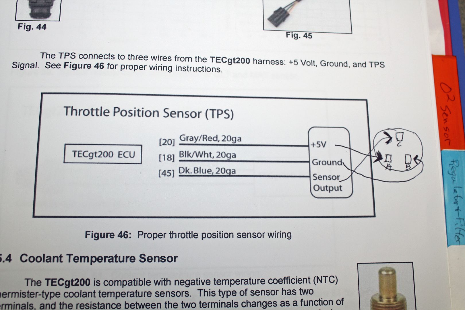
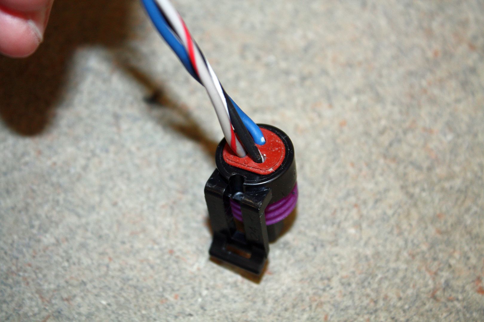
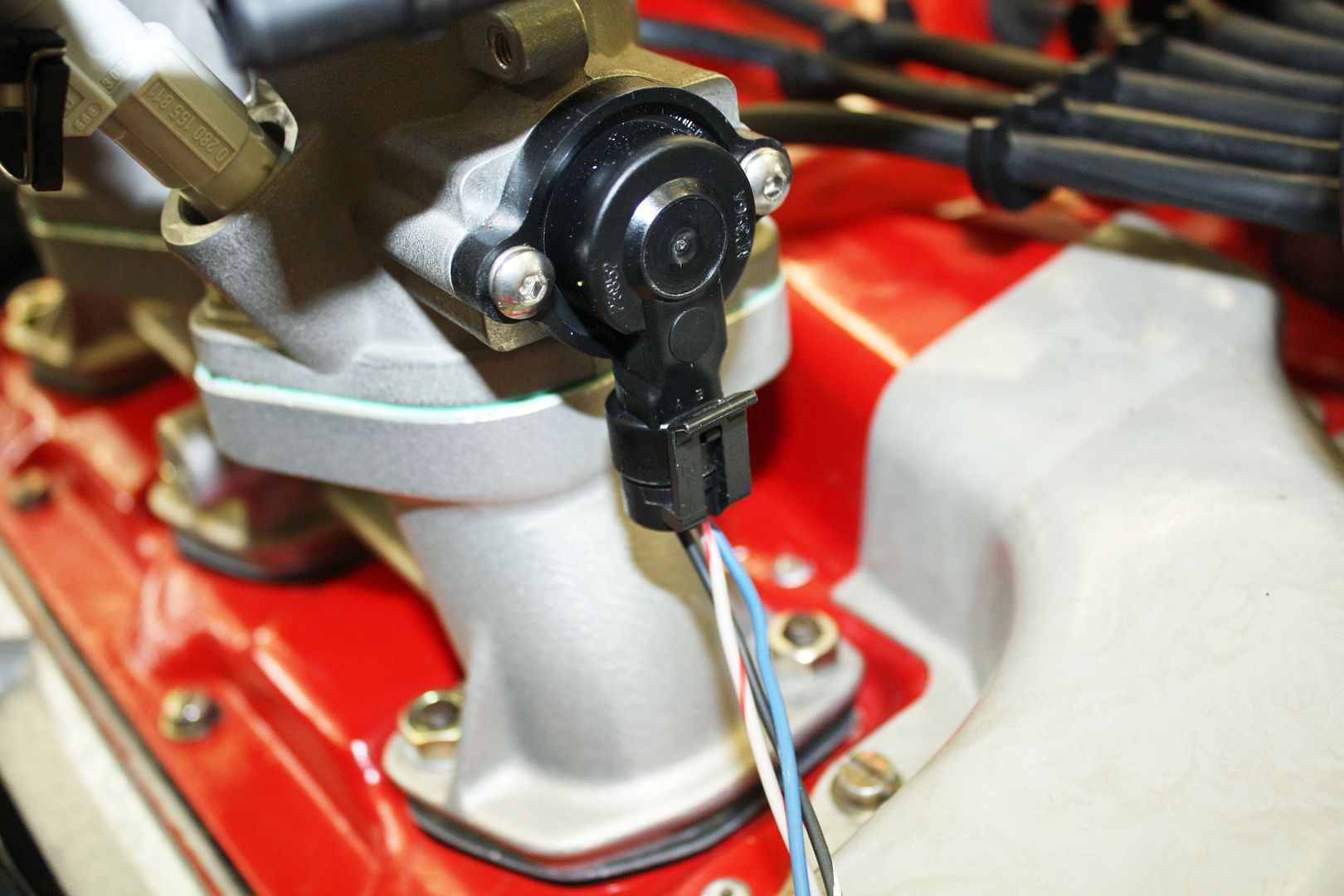
Now that all of the sensors were wired, I could finish running the wiring harness. I ran everything to the center of the rear fuel line.
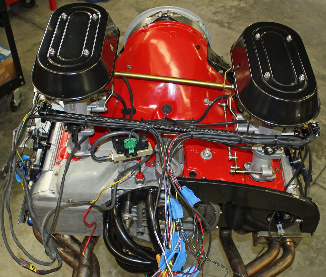
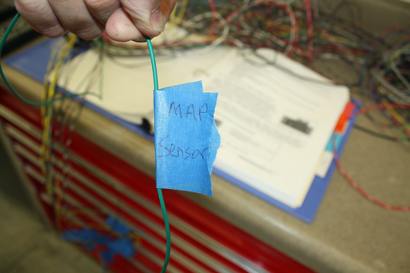
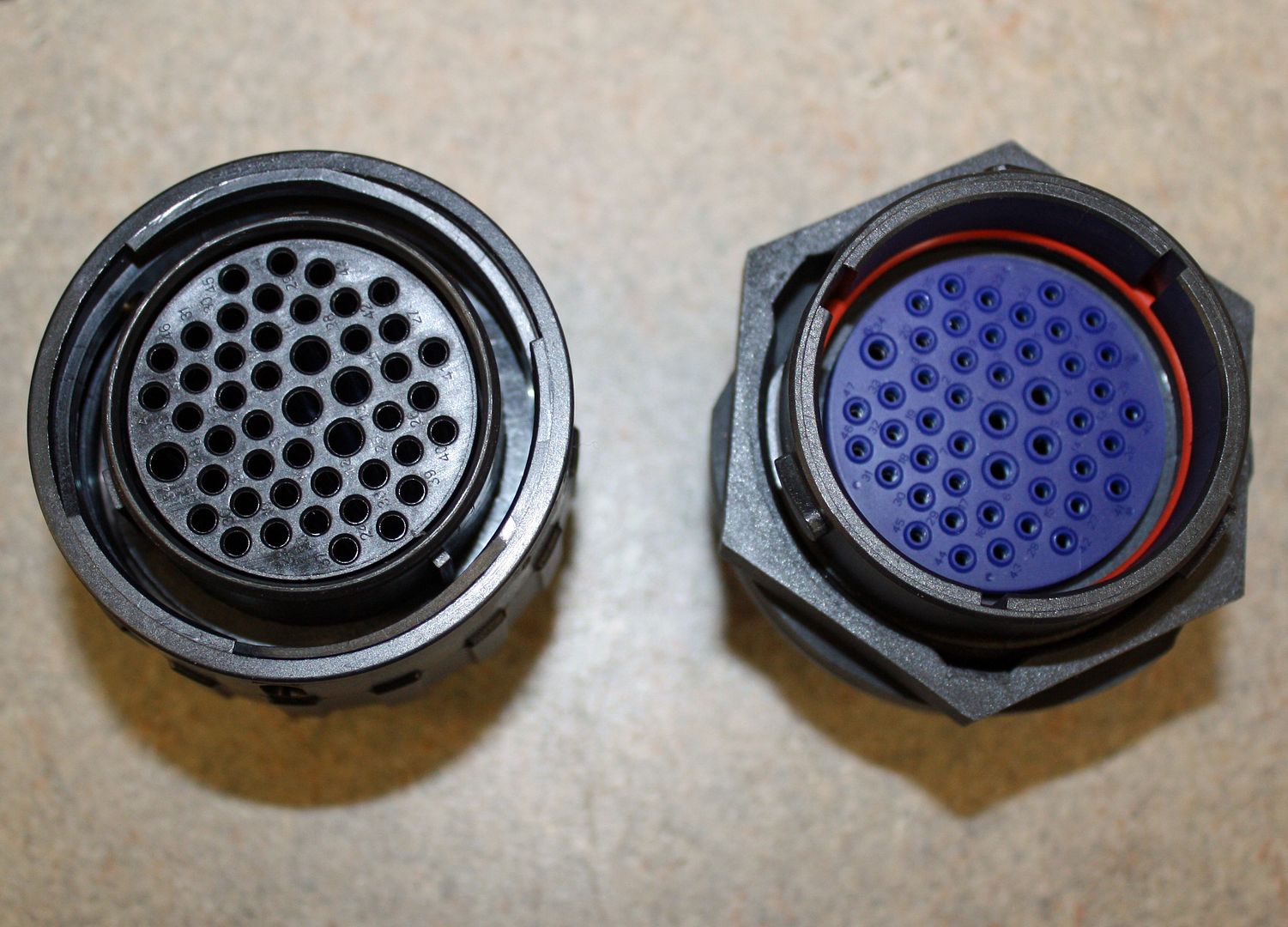
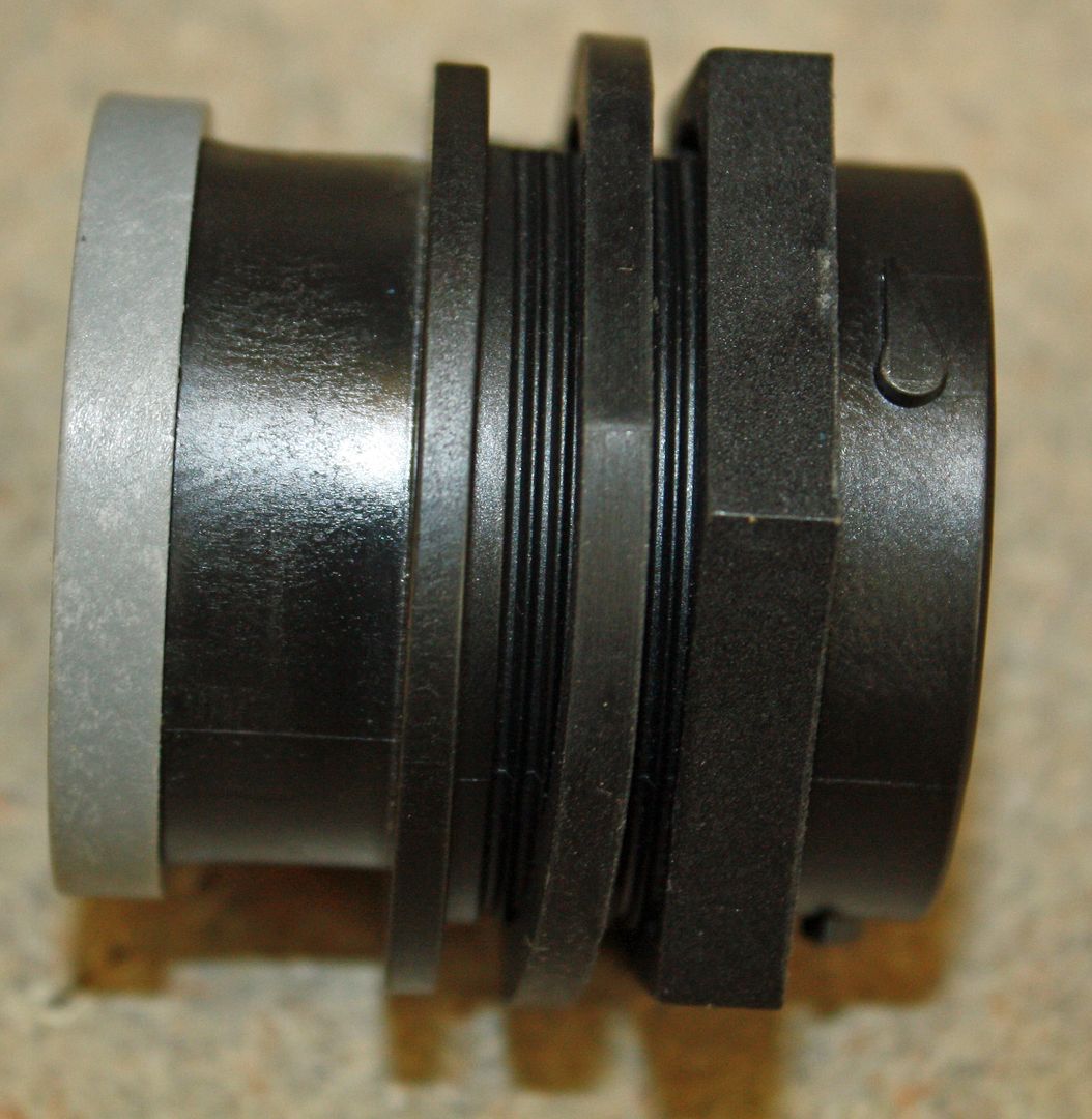
I labeled all of the sensor wires. Now comes the tricky part. I am going to use a 47 pin bulkhead connector. It uses Deutsch terminals which are more compact. Making sure all of those connections on both the female and male connectors are correct will be critical.
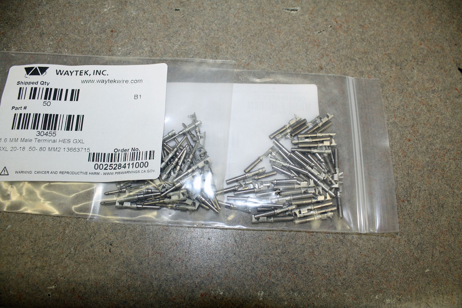
The terminals for the TPS plug came today and were installed this afternoon.


Now that all of the sensors were wired, I could finish running the wiring harness. I ran everything to the center of the rear fuel line.


I labeled all of the sensor wires. Now comes the tricky part. I am going to use a 47 pin bulkhead connector. It uses Deutsch terminals which are more compact. Making sure all of those connections on both the female and male connectors are correct will be critical.


