
Projects on my new, to me, 1974 914-6
 11-21-2018, 07:13 PM
#106
Racer
Thread Starter

I have made some progress that past few days. It had been pointed out to me that I had used the wrong torque figure for the flywheel bolts. The 66ft lb figure was for a nine bolt flywheel while mine was a six bolt with torque figures of 110lb ft. I got out my trusty torque wrench, set it at 110 and had a problem. My socket was very old and worn and slipped out of the bolt head and jamming my hand. As I was afraid I had compromised the bolts, I ordered a new set and a new socket. Now I finally could set the torque where it should be.
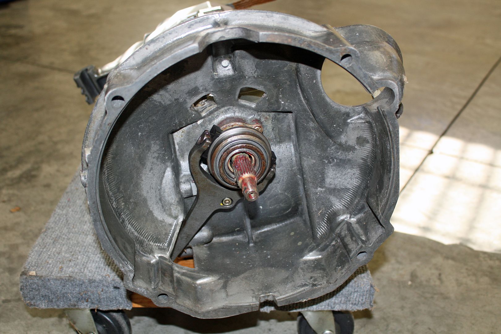
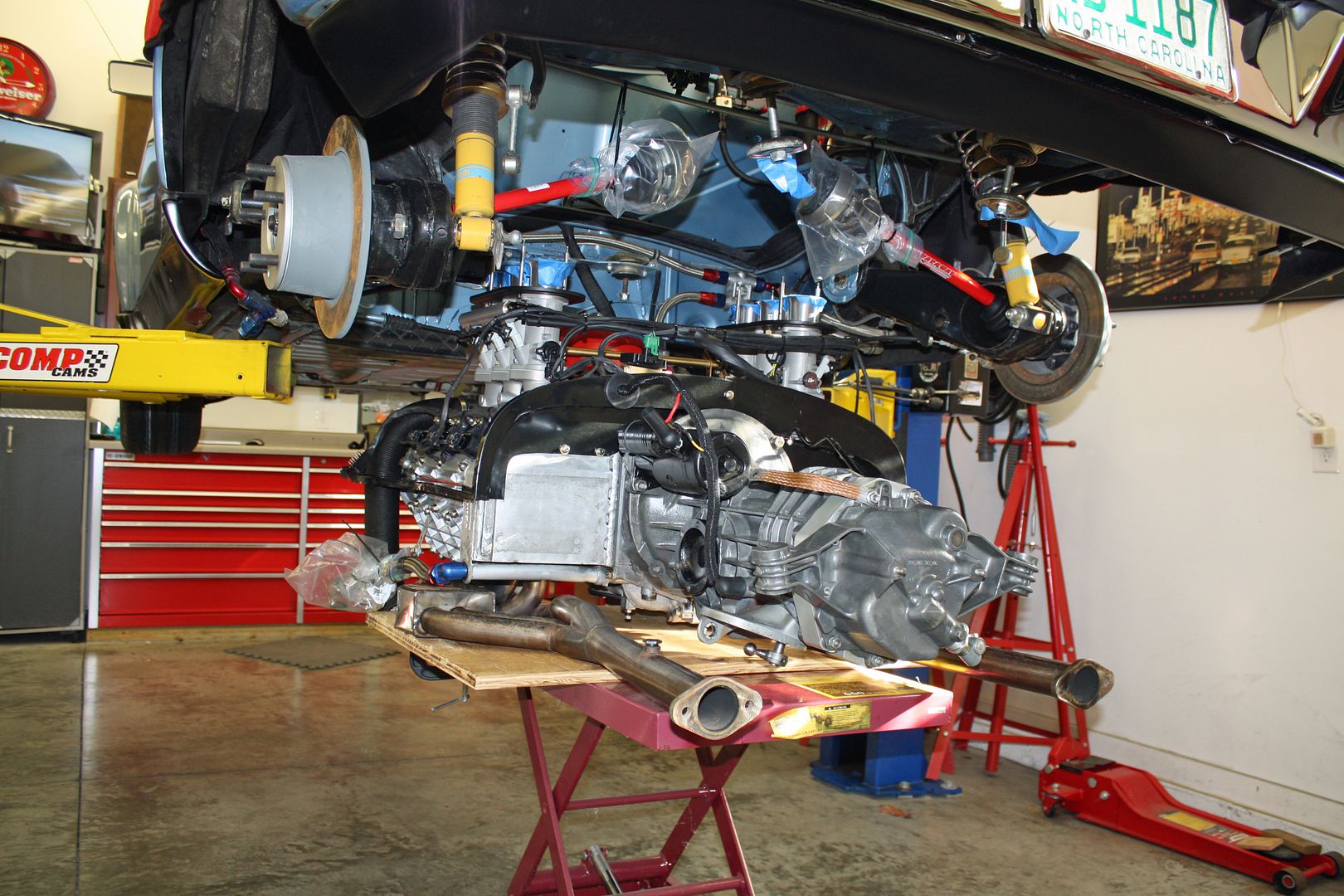
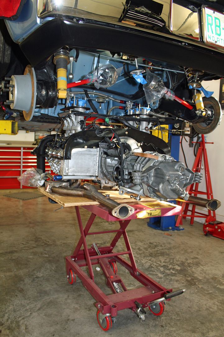
My 12.9 bolts for the pressure plate arrived as well so the clutch could be installed. After installing the throw out bearing and clutch fork, I was ready to mate the transmission with the motor. I used the lift to lift the transmission into place. The starter was also installed as well as the fan belt.
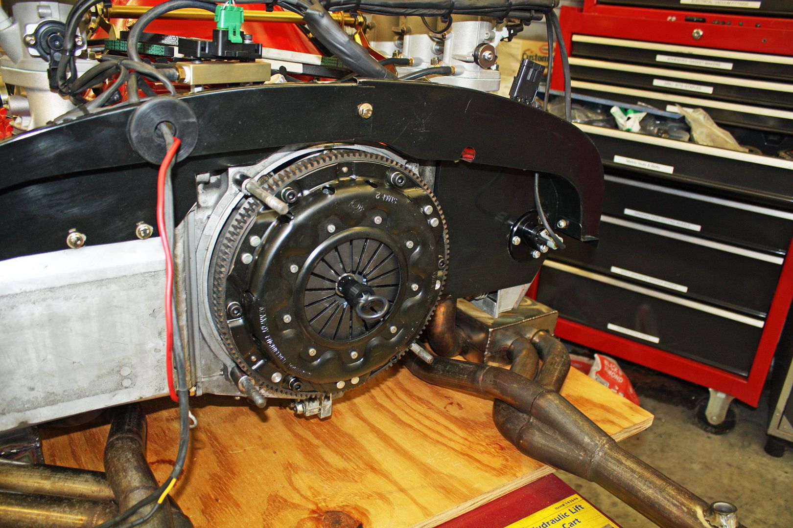
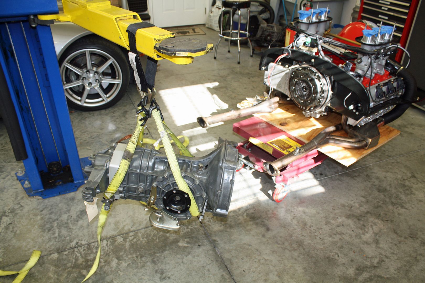
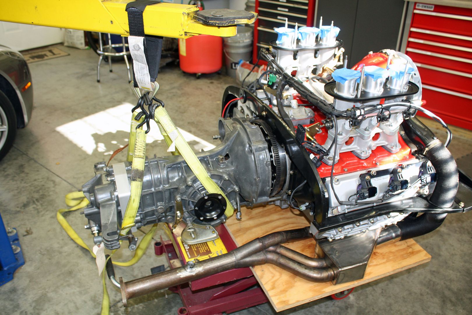
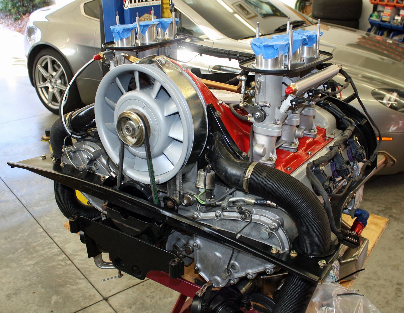
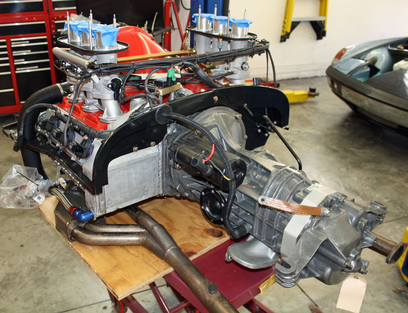
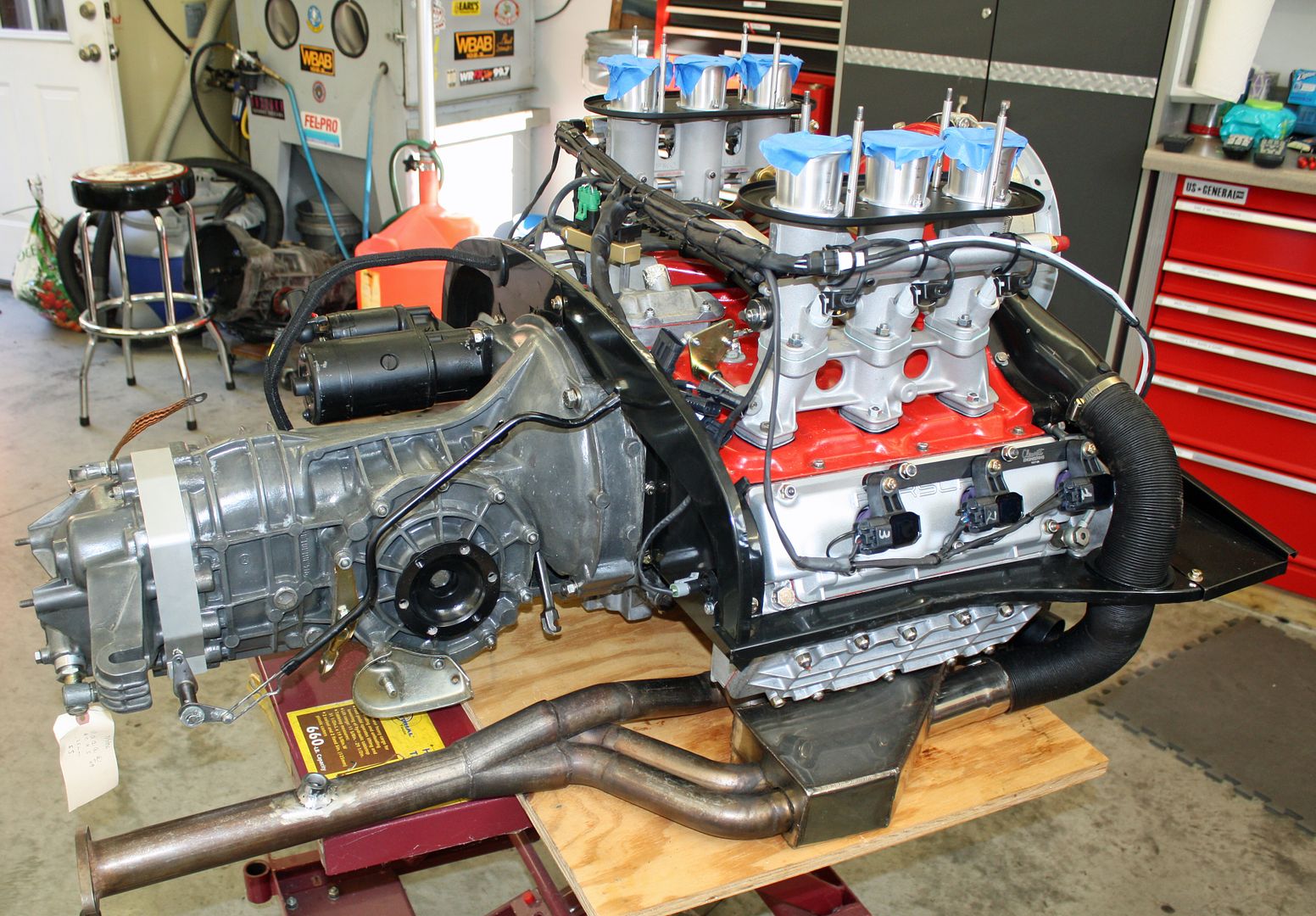
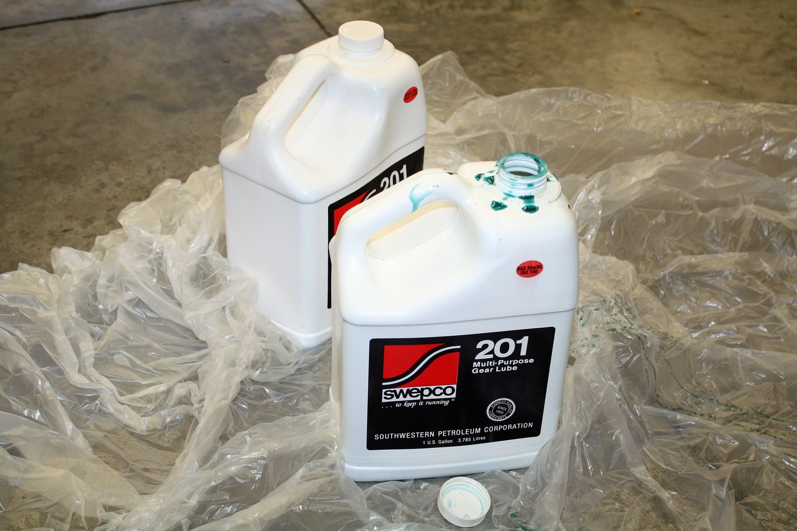
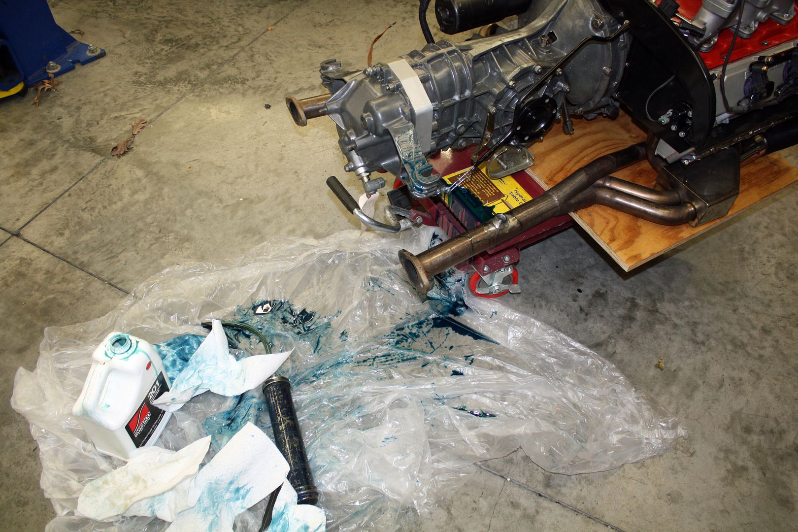
Today I filled the transmission with gear lube, always a messy job. The engine and tranny are ready to go back into the car!!!
My 12.9 bolts for the pressure plate arrived as well so the clutch could be installed. After installing the throw out bearing and clutch fork, I was ready to mate the transmission with the motor. I used the lift to lift the transmission into place. The starter was also installed as well as the fan belt.


Today I filled the transmission with gear lube, always a messy job. The engine and tranny are ready to go back into the car!!!


 11-21-2018, 07:24 PM
#108
Racer
Thread Starter
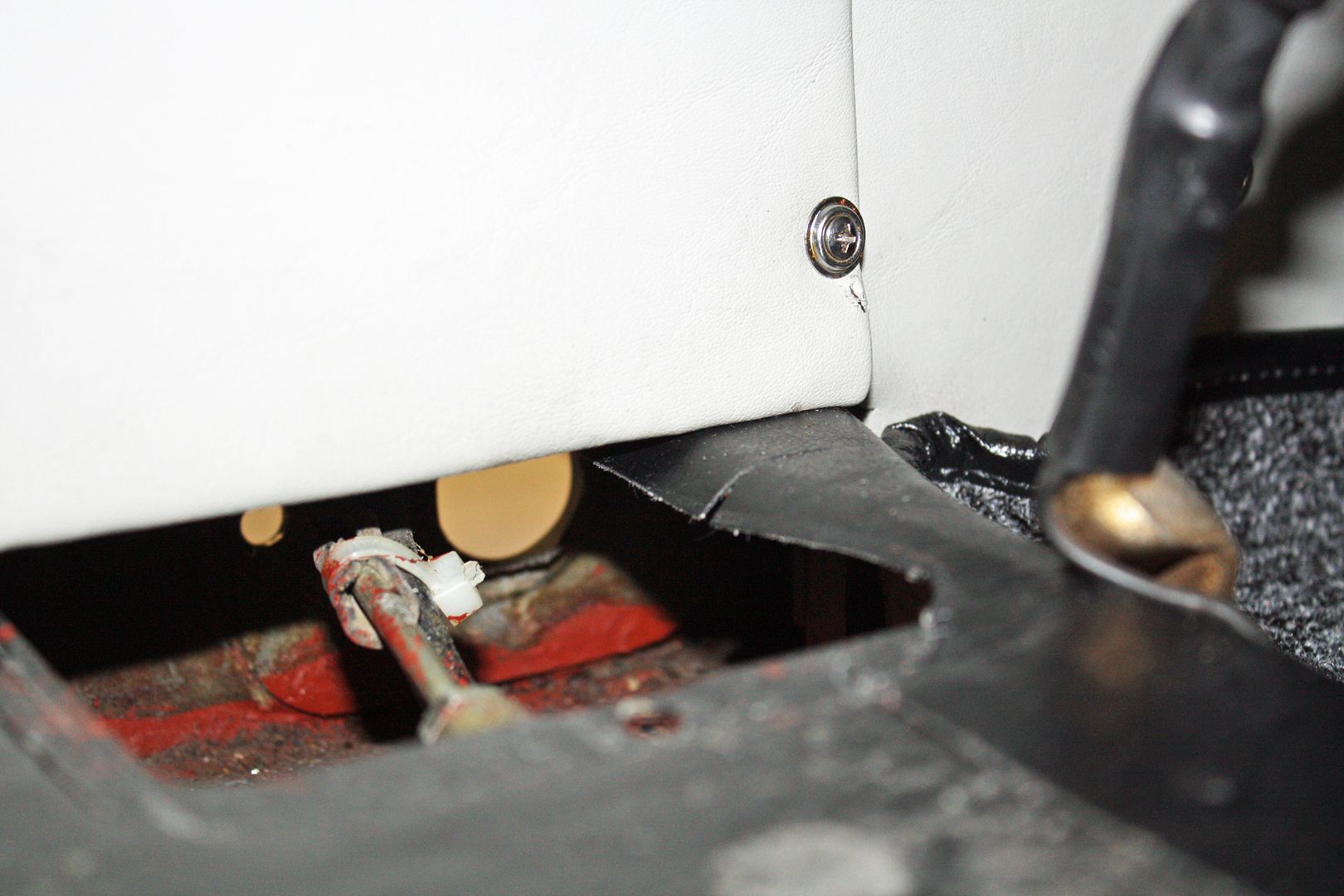
Based on the positive comment on the Jwest shift linkage, I decided to use it. I removed the shifter, undid the pinch bolt and removed the front shift rod through the firewall. The shift rod bushing at the firewall must also be removed.
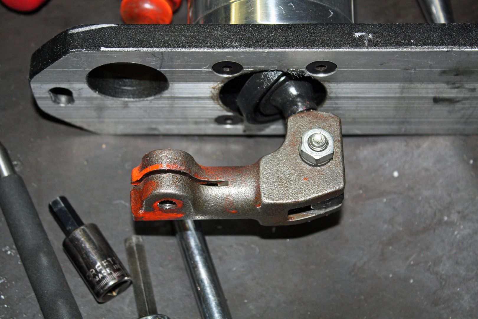
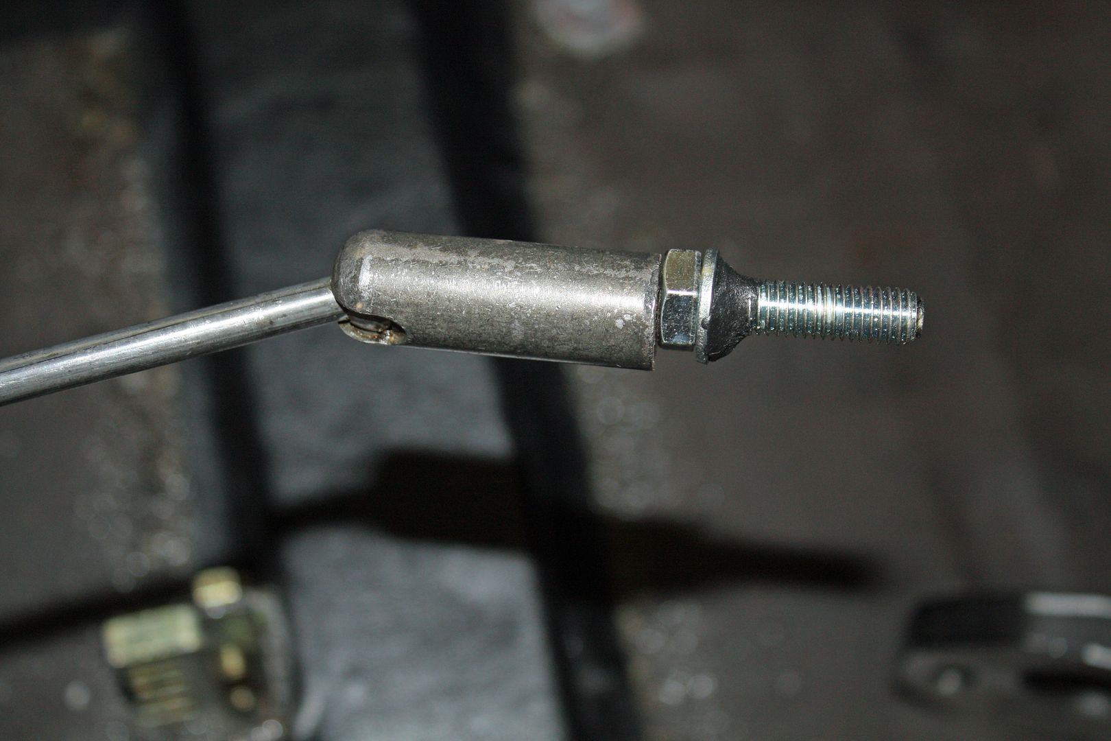
The splined end of the shift rod must be removed and then welded onto a new rod supplied in the kit. Since I don't weld, I took everything over to my son's house. He proceeded to ground off the existing welds and then weld the end to the new rod at the prescribed length. After cleaning up the welds at home, I painted the welded area to prevent corrosion.
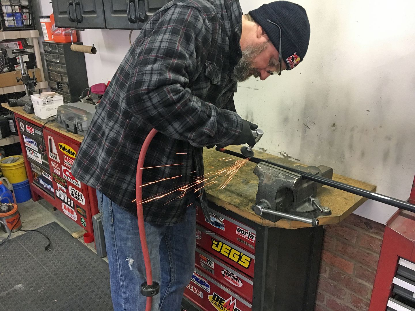
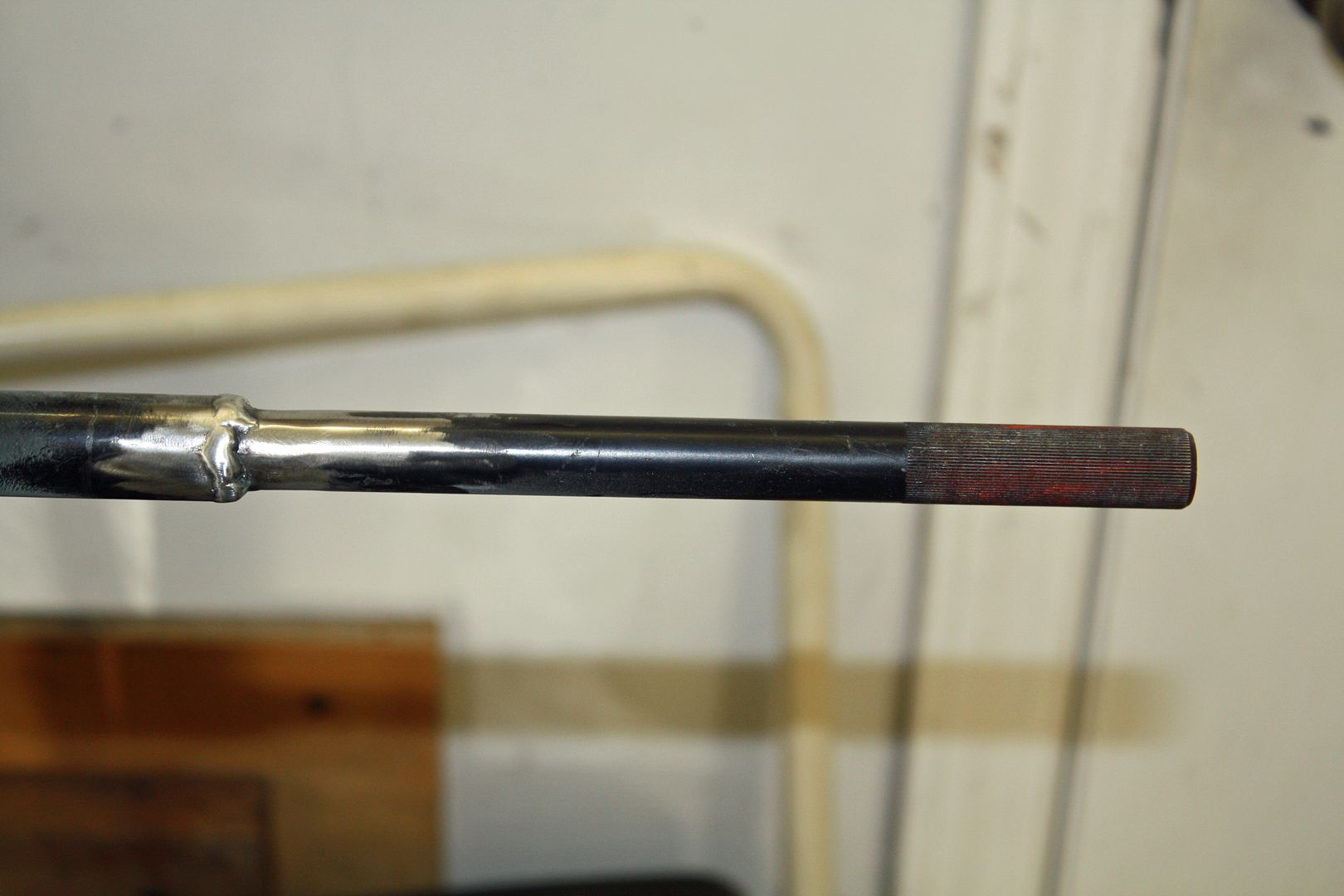


The splined end of the shift rod must be removed and then welded onto a new rod supplied in the kit. Since I don't weld, I took everything over to my son's house. He proceeded to ground off the existing welds and then weld the end to the new rod at the prescribed length. After cleaning up the welds at home, I painted the welded area to prevent corrosion.


 11-21-2018, 07:35 PM
#109
Racer
Thread Starter
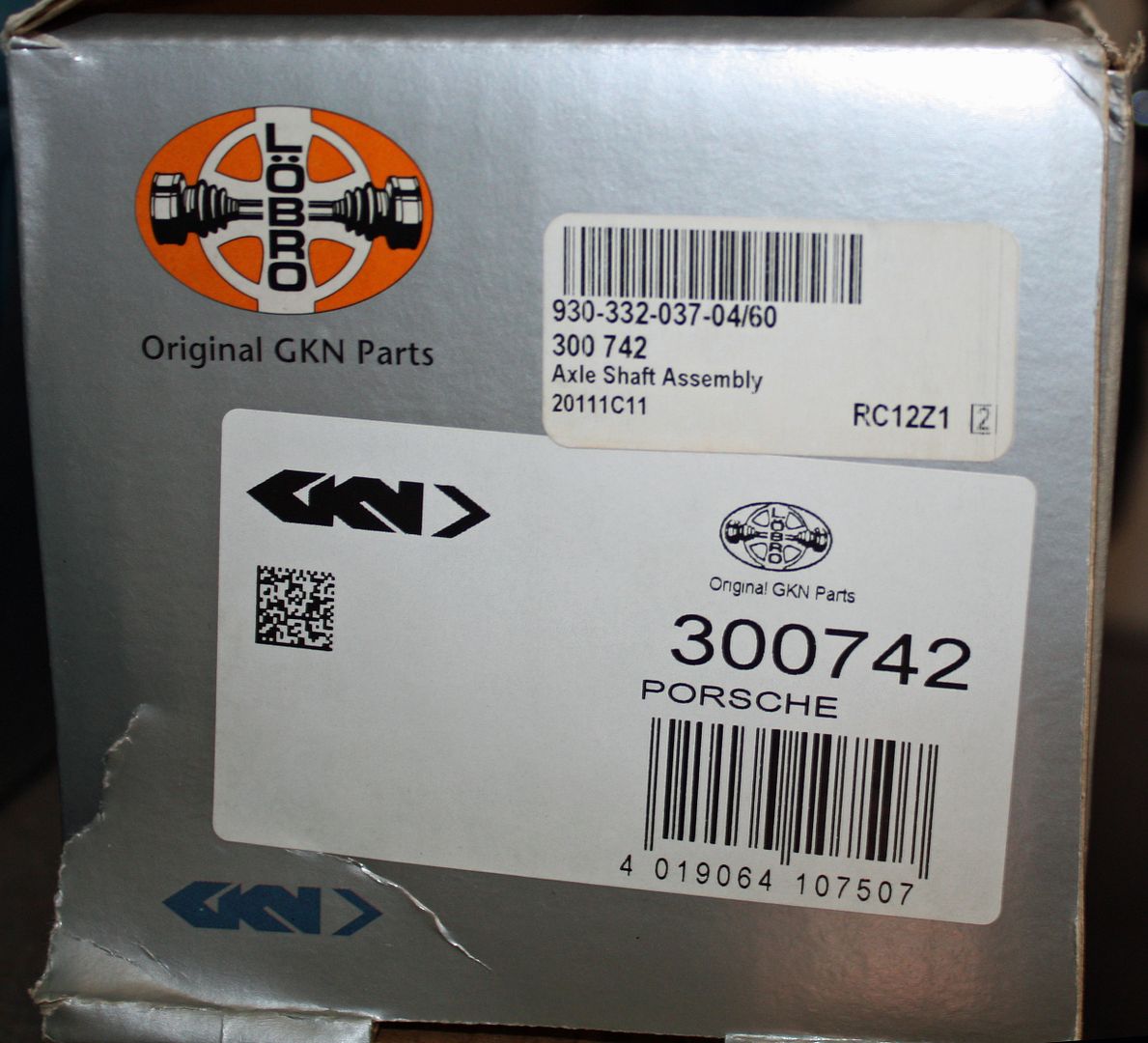
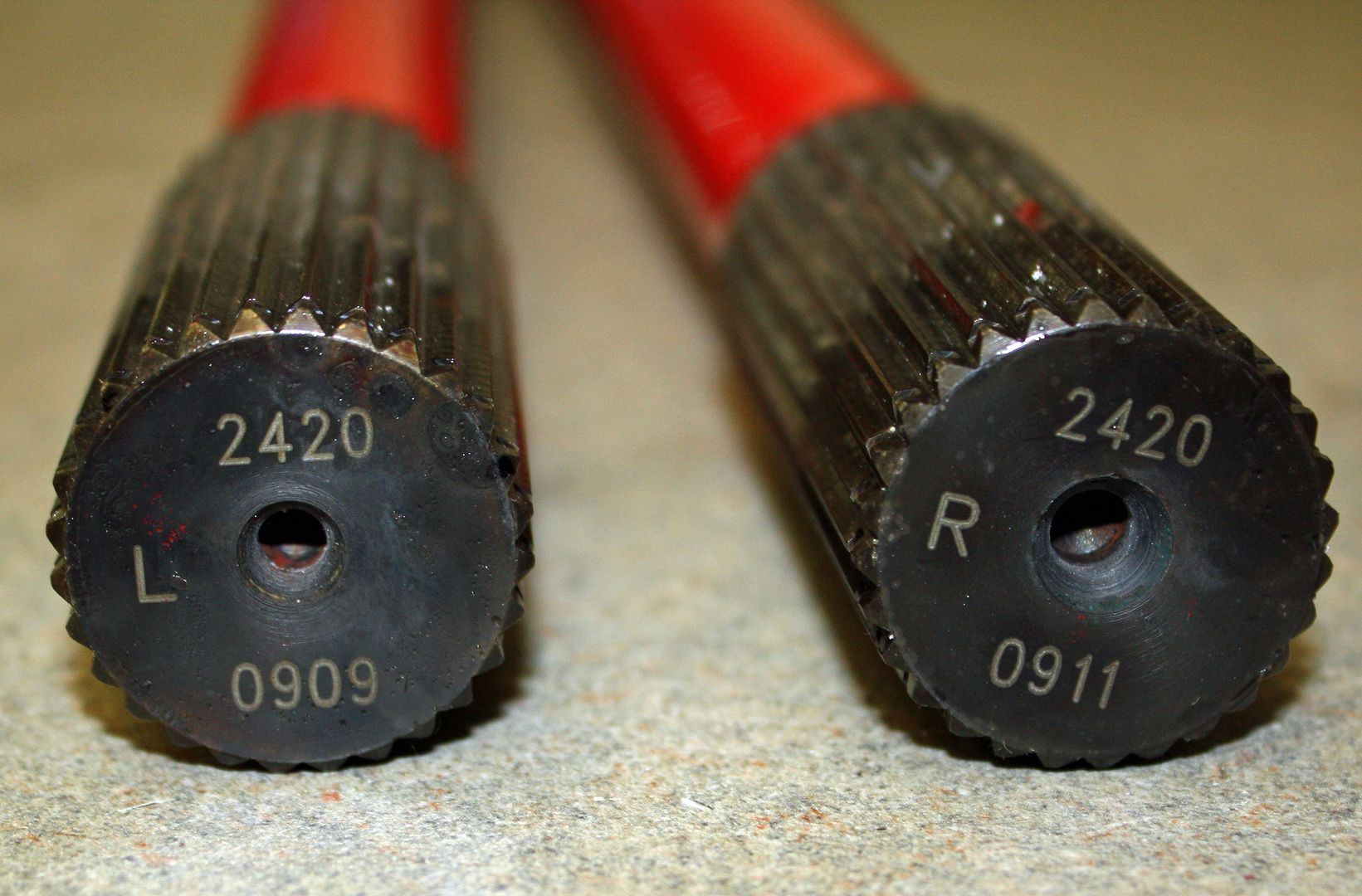
The previous owner, Ed, had done a lot of research into upgrading the axles. He found six bolt flanges using M10 1.5 bolts that could be used with turbo axles. The car came with two brand new turbo axles still in the boxes.
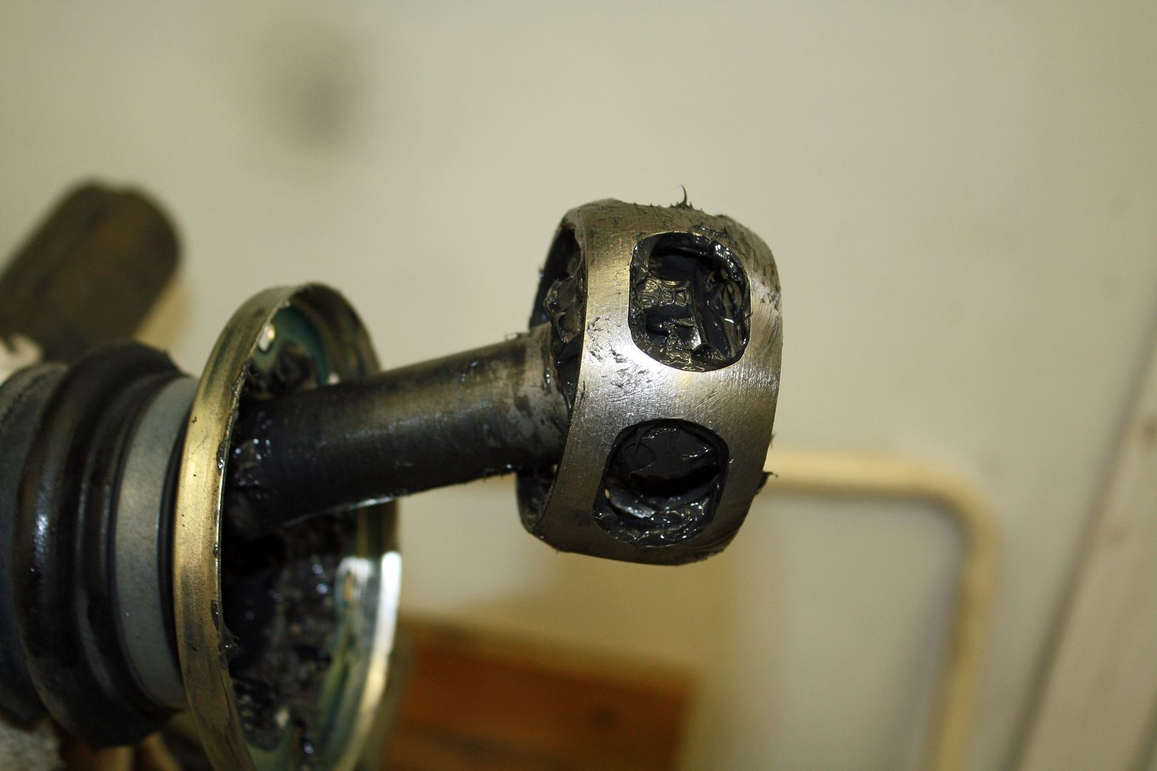
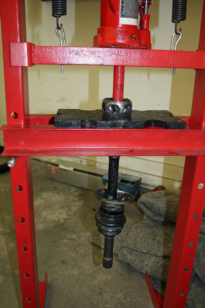
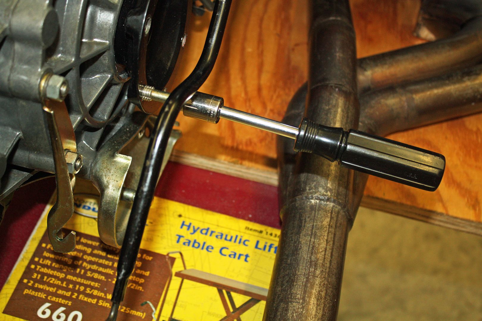
The problem is that 911 axles are 3/4" shorter than 914 axles. To solve that issue, Ed had ordered a set of Sway-Away axles that are the proper length. To mount them, I would need to remove the CV joints from the turbo axles and install them on the Sway-Away axles. I removed the snap ring but could not get the CV to slide off the end of the axle. Since I was going to my son's house anyway, I took the axles along. My son has a small press and it did the trick. Since my son was busy finishing up his 911 Tesla, I took the press with me and will remove the other CV's and transfer them. It is good to have a son with lots of goodies and expertise!!!
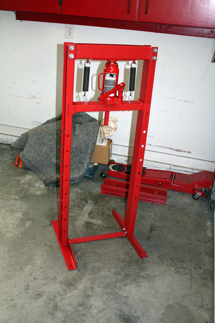


The problem is that 911 axles are 3/4" shorter than 914 axles. To solve that issue, Ed had ordered a set of Sway-Away axles that are the proper length. To mount them, I would need to remove the CV joints from the turbo axles and install them on the Sway-Away axles. I removed the snap ring but could not get the CV to slide off the end of the axle. Since I was going to my son's house anyway, I took the axles along. My son has a small press and it did the trick. Since my son was busy finishing up his 911 Tesla, I took the press with me and will remove the other CV's and transfer them. It is good to have a son with lots of goodies and expertise!!!


 11-23-2018, 05:16 PM
#110
Racer
Thread Starter
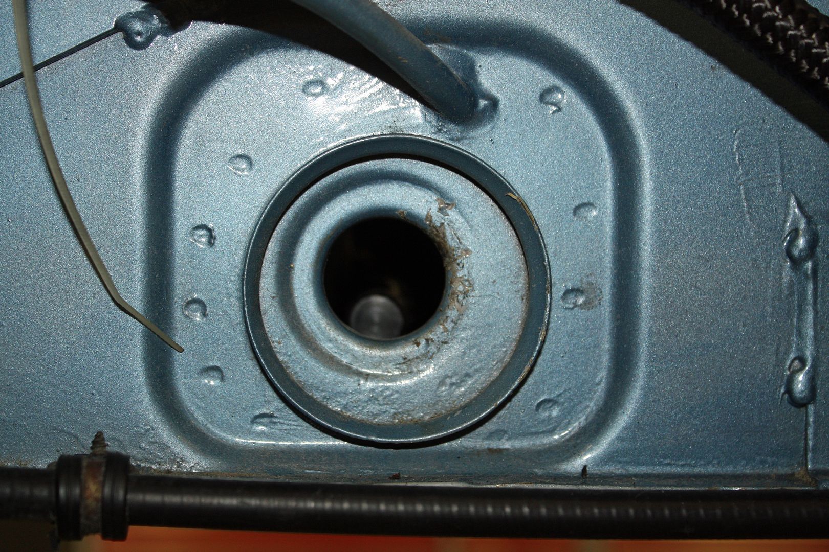
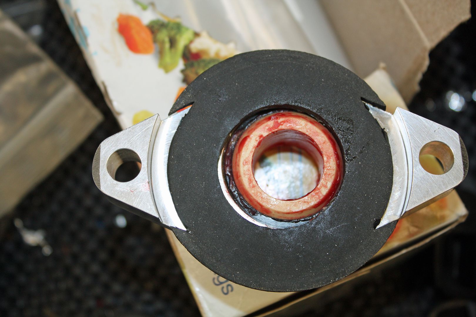
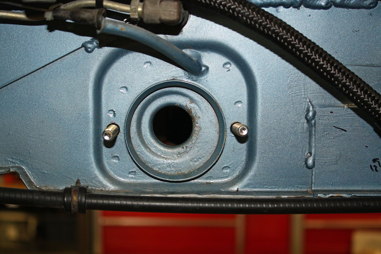
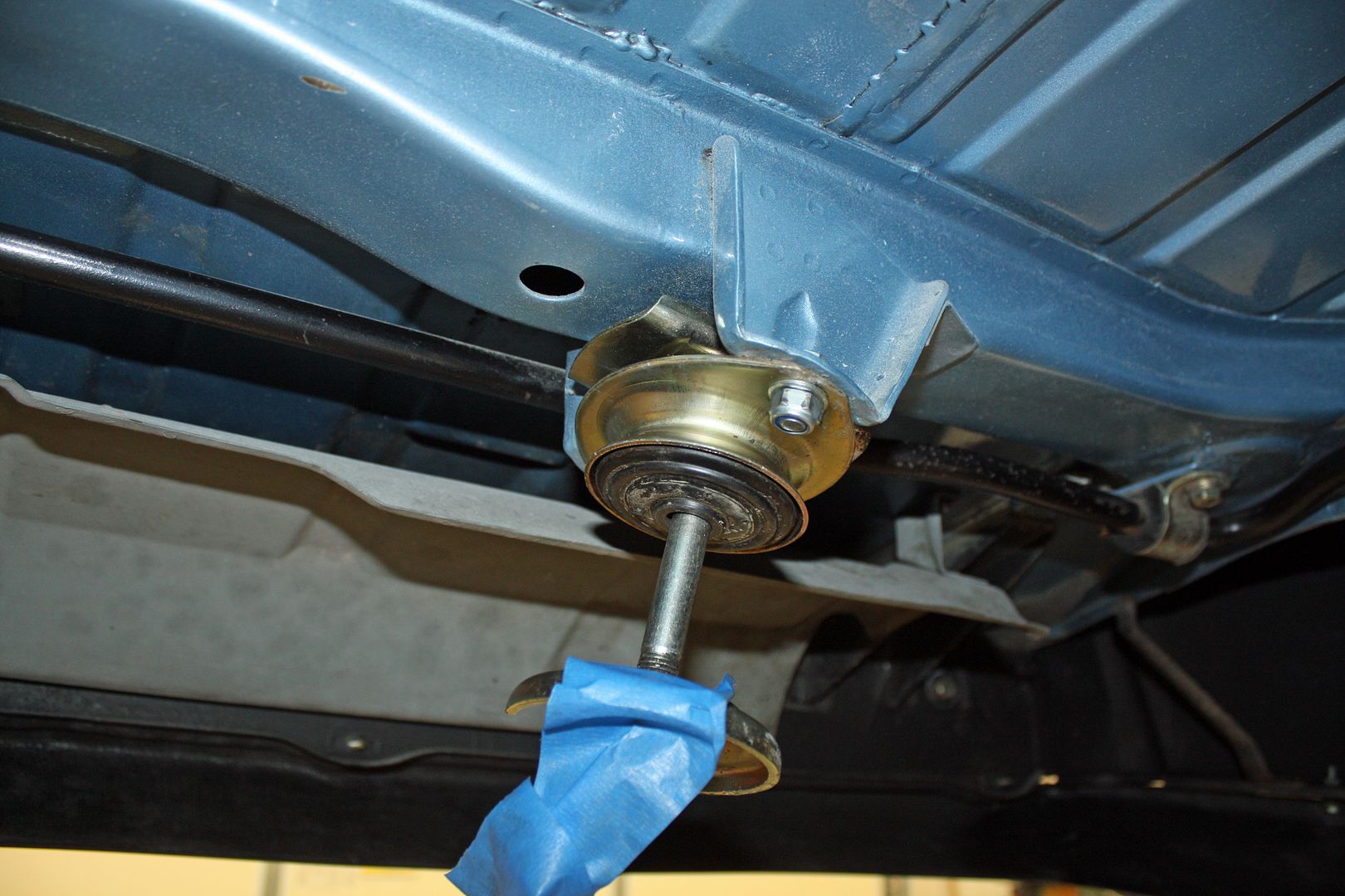
After the house cleaning party this morning, I worked on installing the Jwest Side Shift Linkage. Installing the shifter bearing on the firewall was the task at hand. The hole that the shifter rod goes through is not centered in the round area in the firewall. Consequently, the bearing is offset to the driver's side and up. To help place the bearing support correctly, I slid the shift rod through the bearing. Once I had it correctly placed, I marked the holes for drilling.
The instructions called for using a magnet to place the bolts into the holes from the tunnel. To make sure they stayed in the holes, I placed some strip caulk below the head and pushed hard against the bolts once they were through the holes. This not only served to seal these bolts but they stayed well enough that I could completely tighten the nuts.
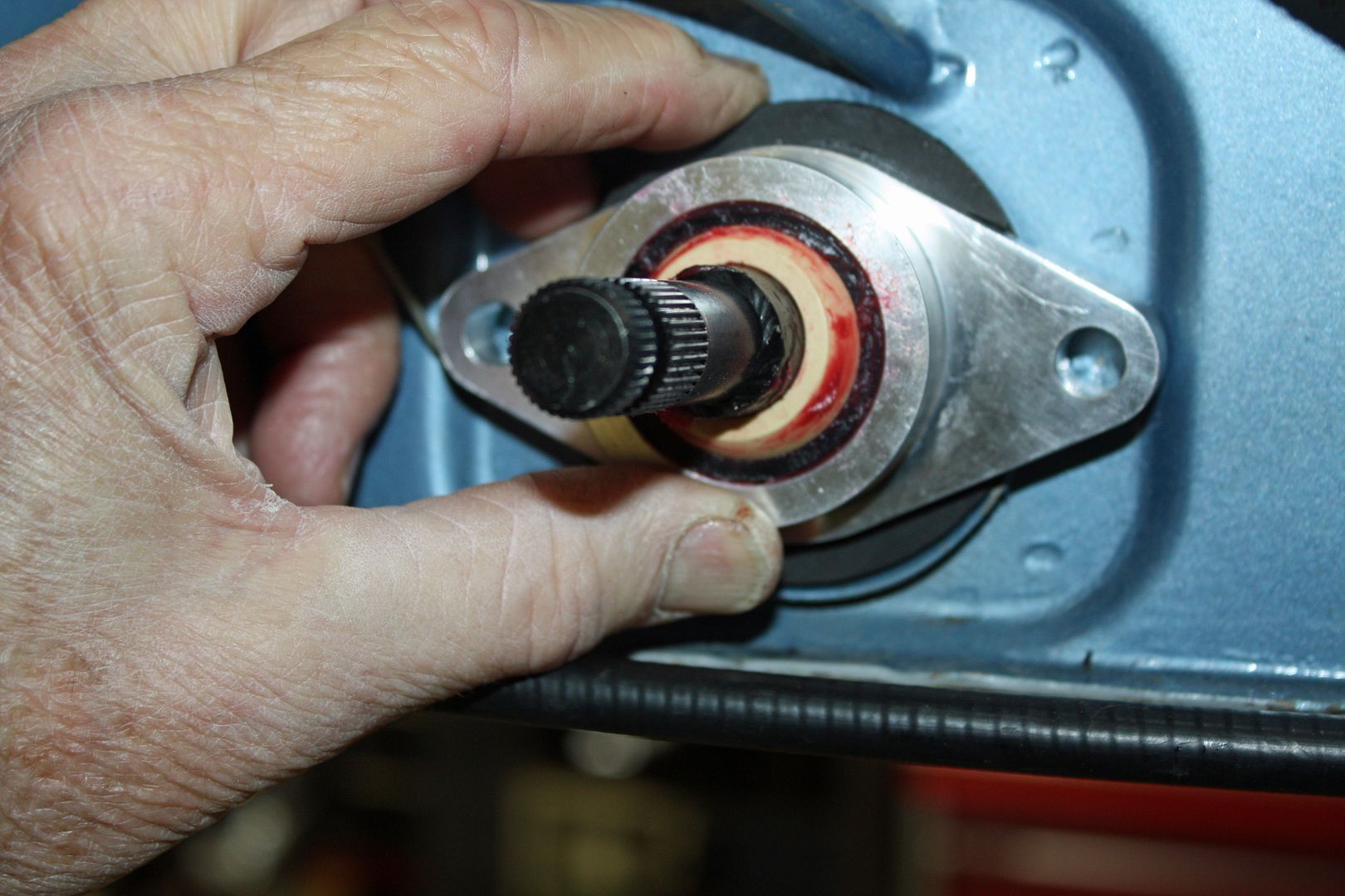
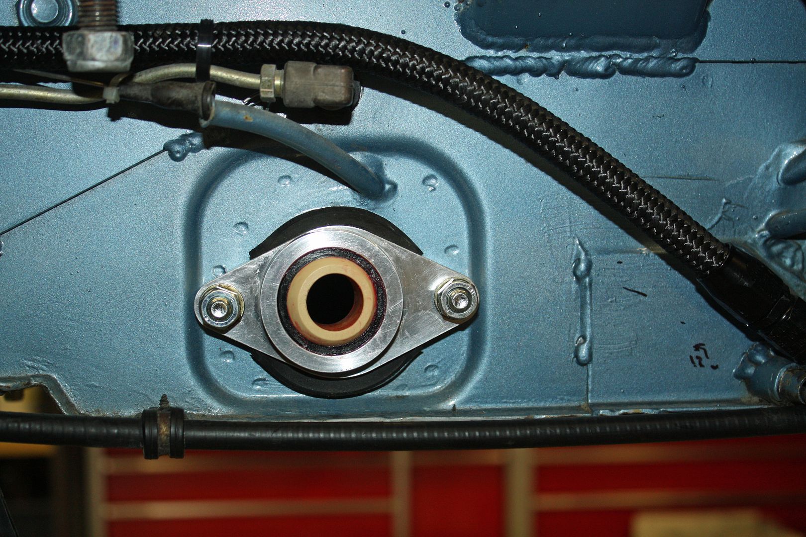
I then slid the shift rod through the bearing and slid it into the pinch clamp on the shifter. With the shifter then bolted back into place, I could install the boot over the shift rod at the firewall. It is secured with the supplied zip tie.
The instructions called for using a magnet to place the bolts into the holes from the tunnel. To make sure they stayed in the holes, I placed some strip caulk below the head and pushed hard against the bolts once they were through the holes. This not only served to seal these bolts but they stayed well enough that I could completely tighten the nuts.
I then slid the shift rod through the bearing and slid it into the pinch clamp on the shifter. With the shifter then bolted back into place, I could install the boot over the shift rod at the firewall. It is secured with the supplied zip tie.


 11-24-2018, 05:07 PM
#111
Racer
Thread Starter
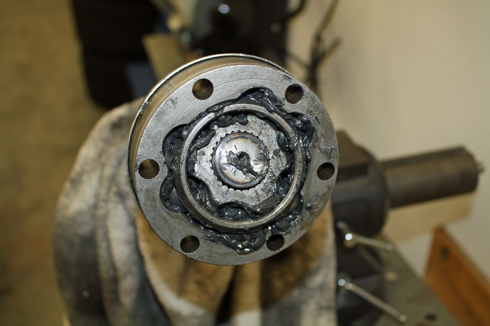
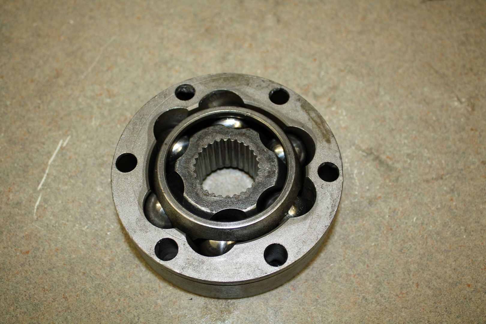
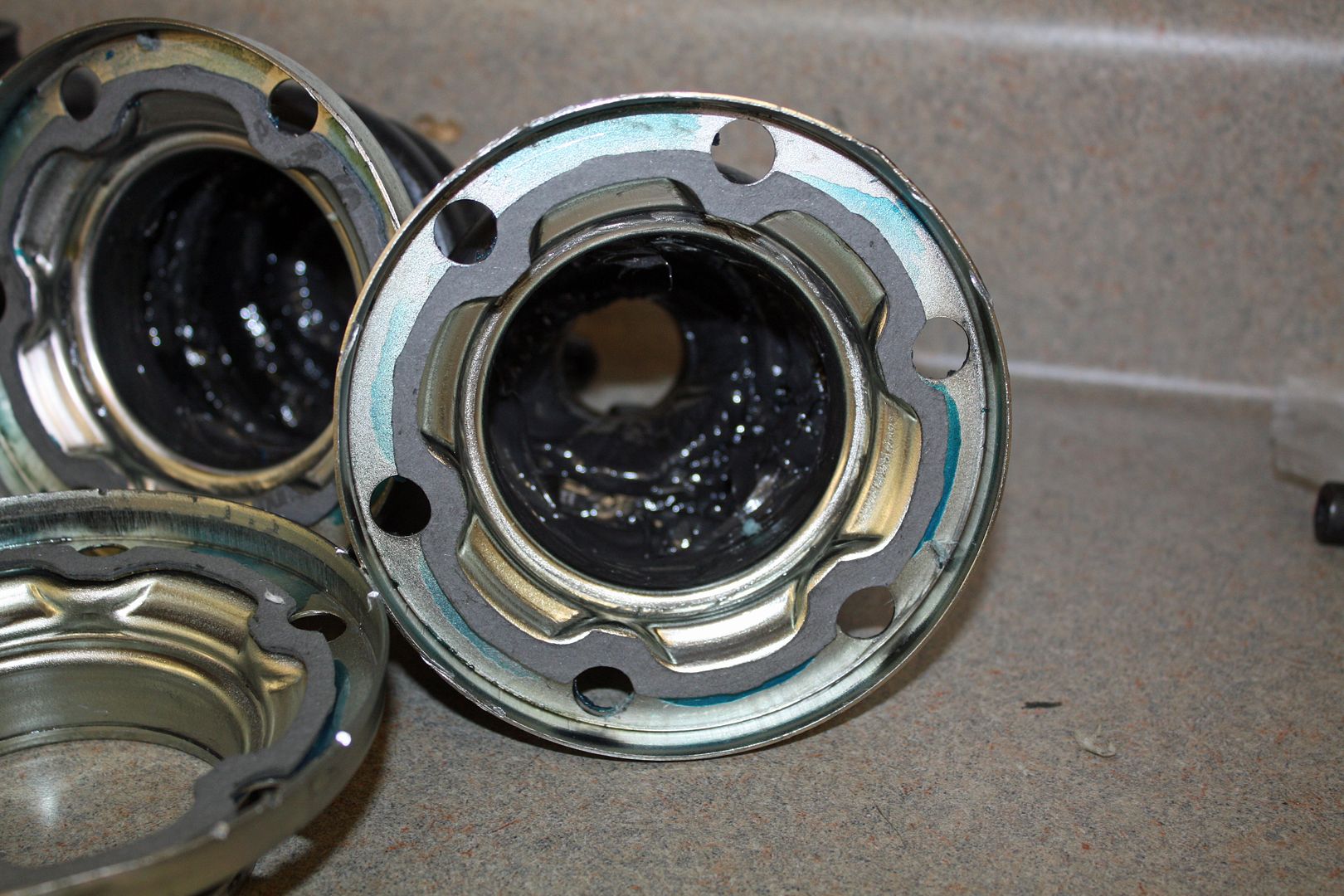
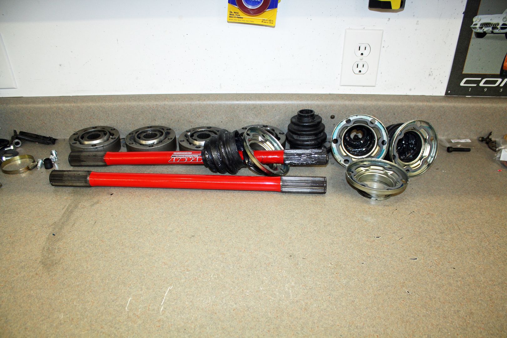
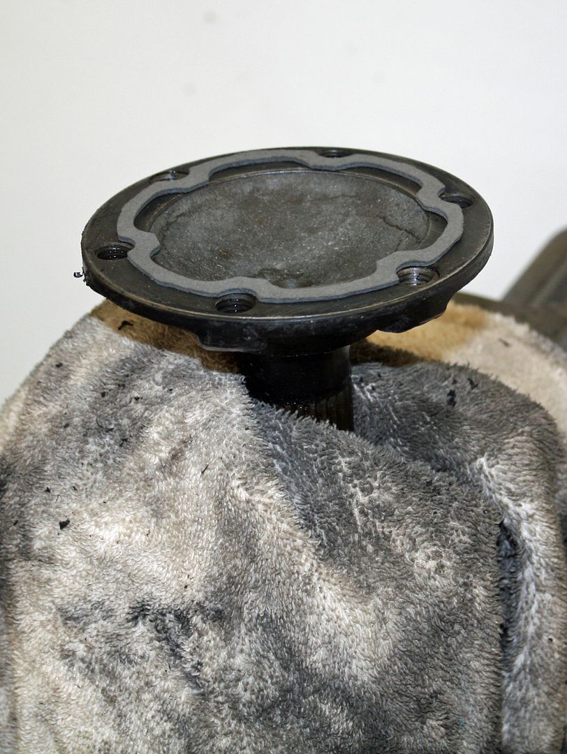
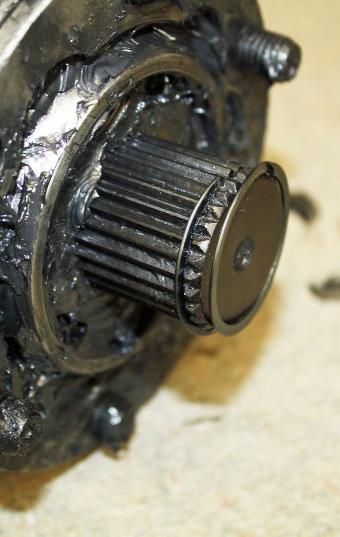
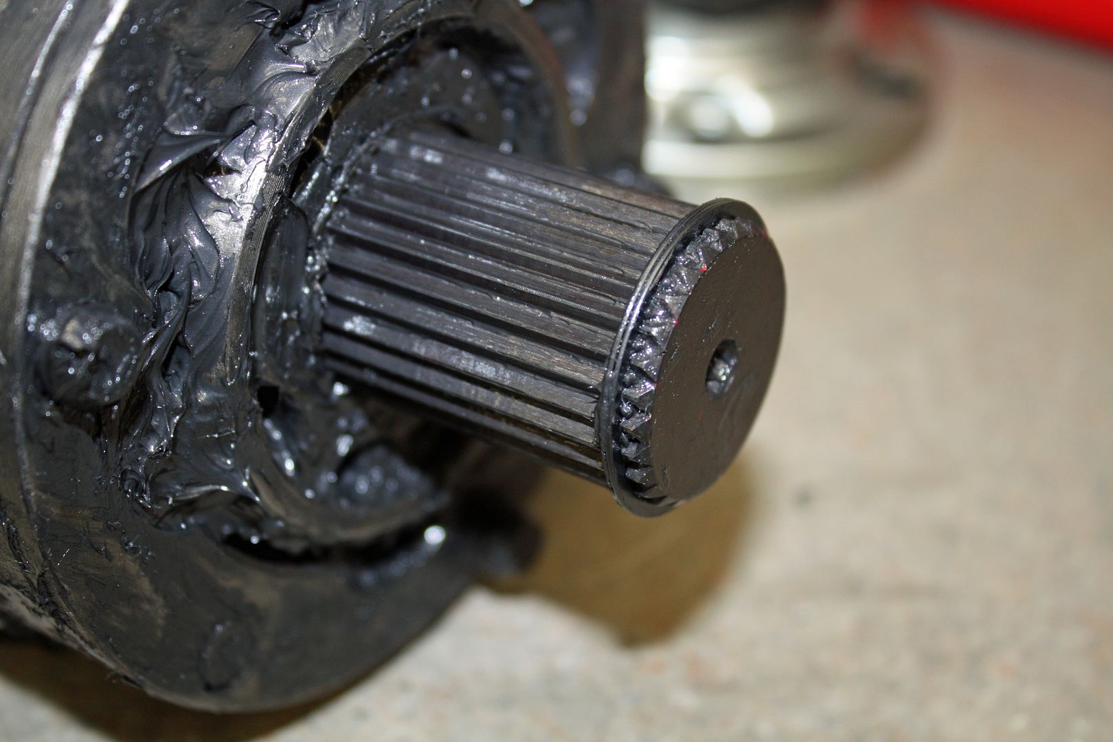
Another messy day of working with the CV's. There is a cap on the end of the CV joins that has to be removed. With this cap out of the way, the snap rings are exposed. After removing the snap rings, I detached the boot from the CV. At this point I removed all of the ***** and the outer ring. Now I could place the axle assembly on the press to remove the rest of the CV.
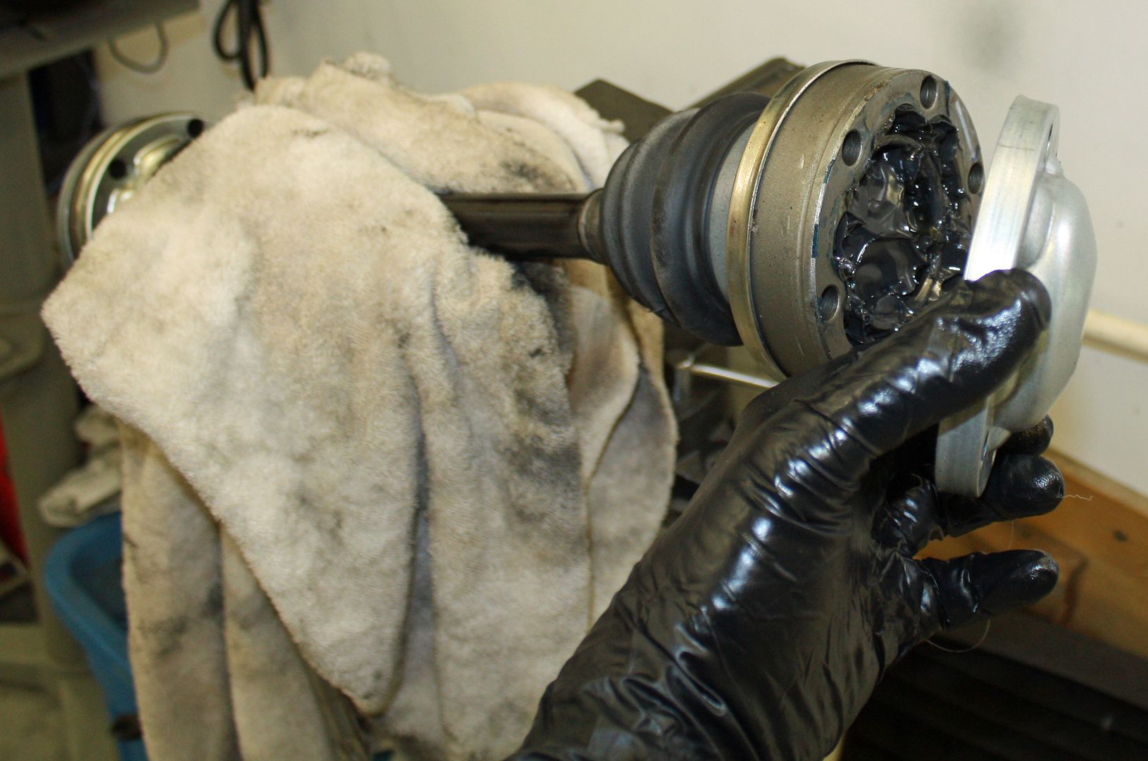
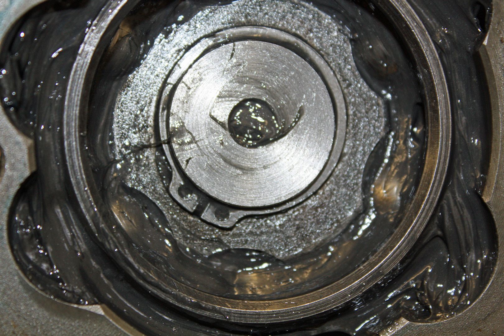
Now that I had everything apart, I cleaned the CV parts and re-installed the *****. I also cleaned up the metal boot mounts and installed seals on them.
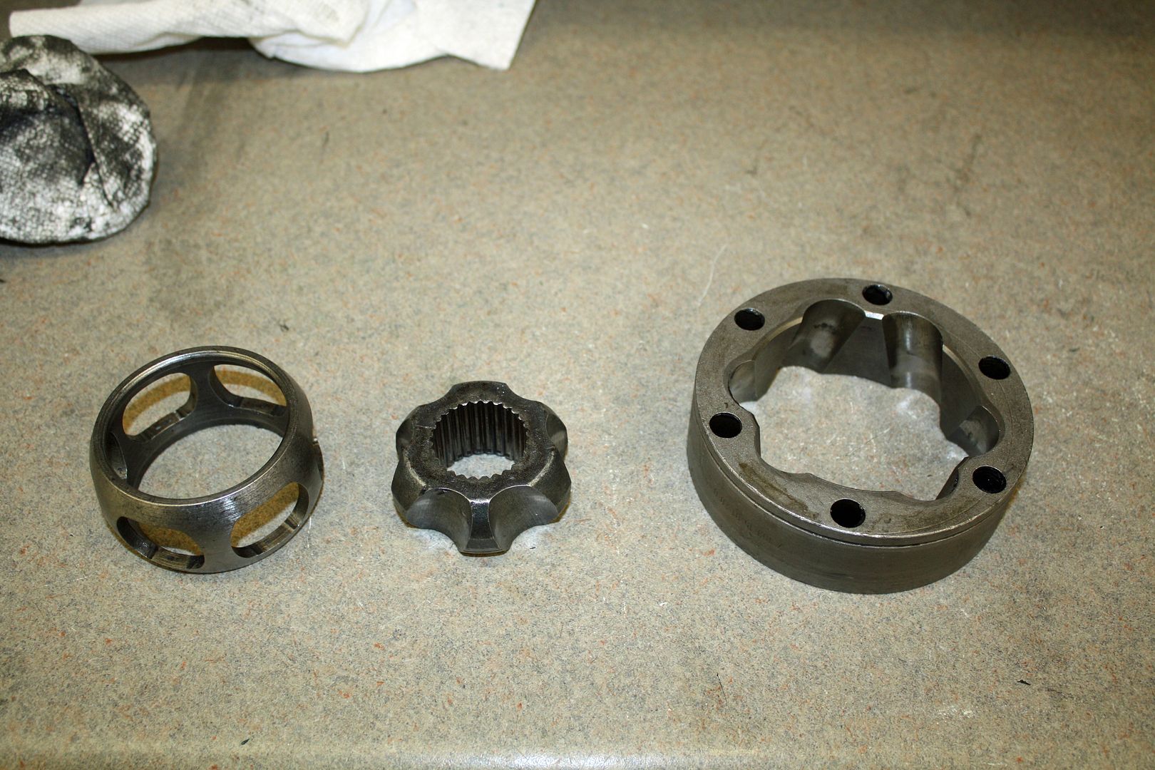


Now that I had everything apart, I cleaned the CV parts and re-installed the *****. I also cleaned up the metal boot mounts and installed seals on them.


 11-24-2018, 05:15 PM
#112
Racer
Thread Starter
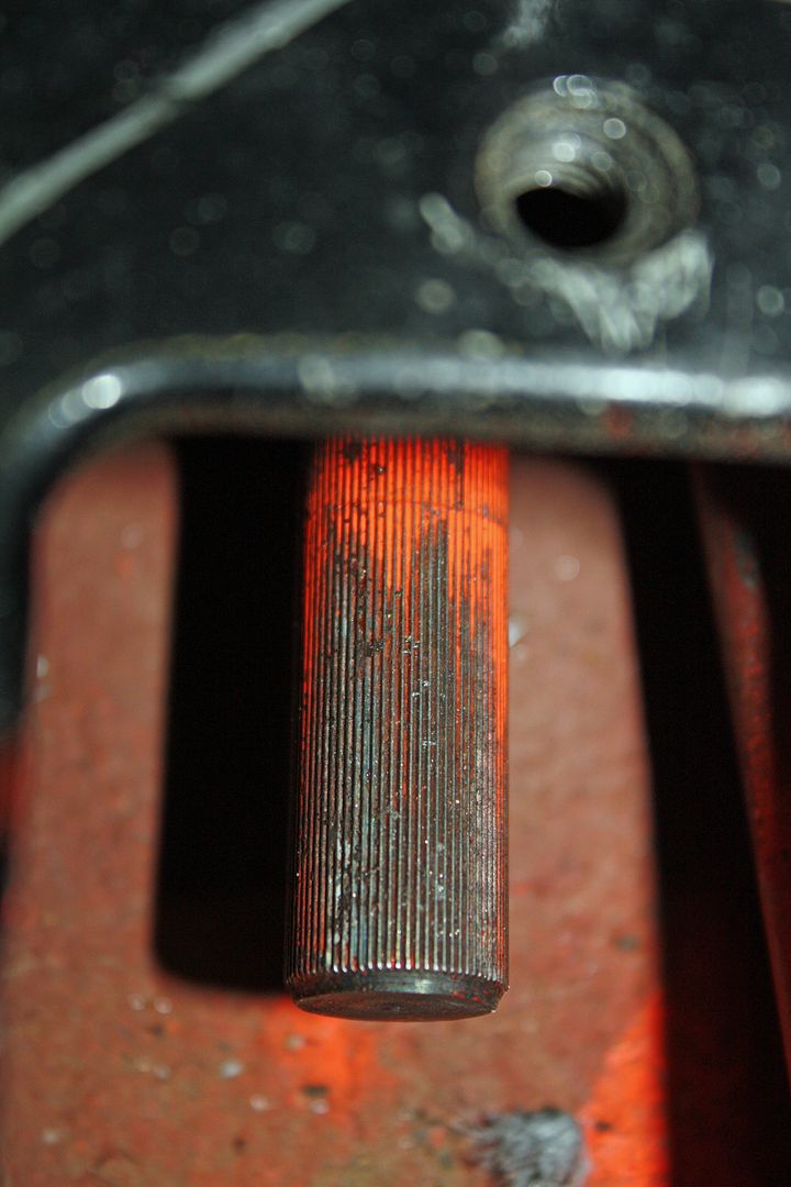
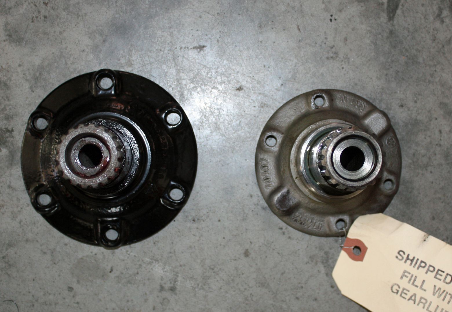
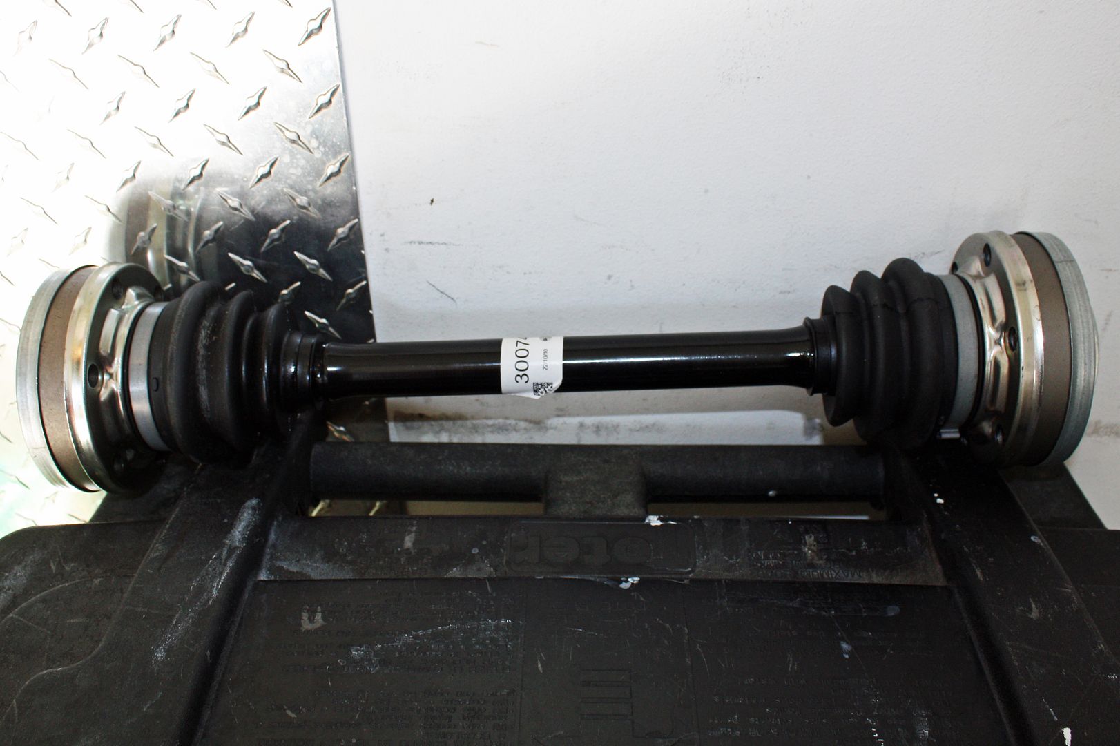
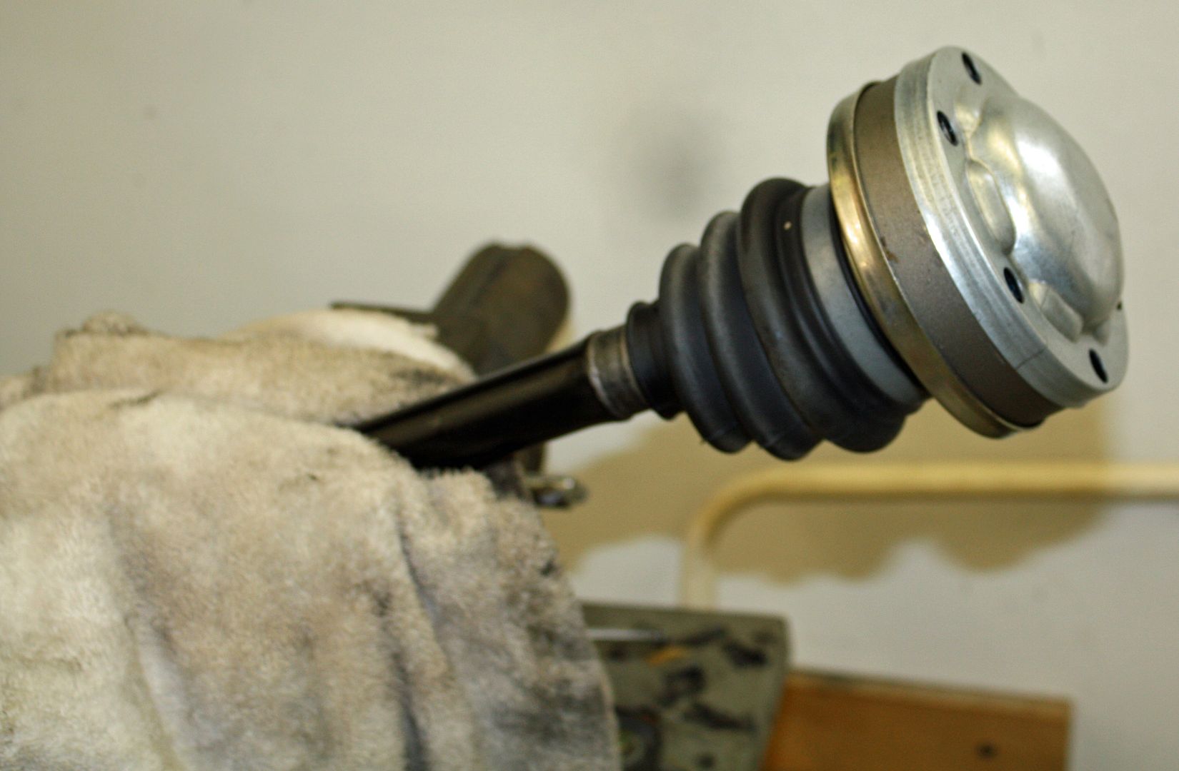
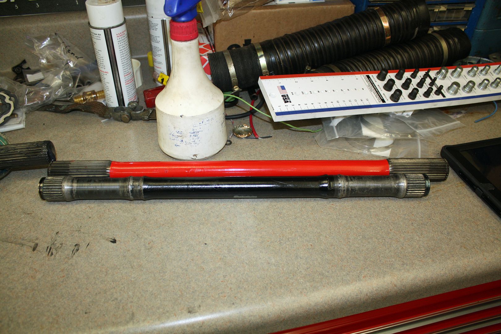
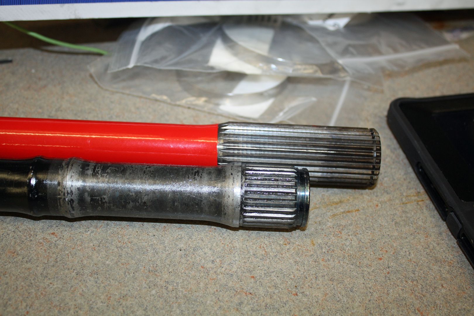
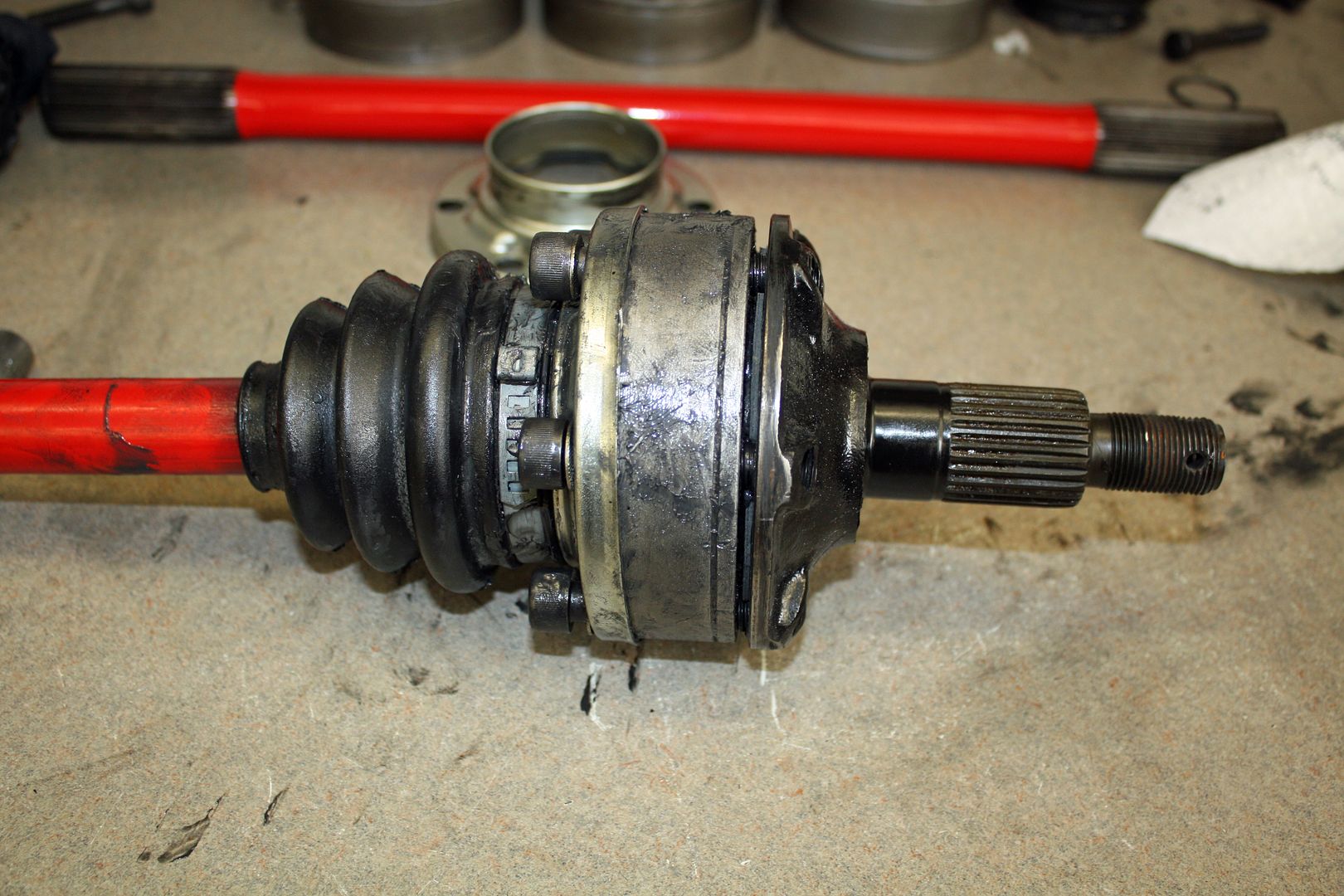
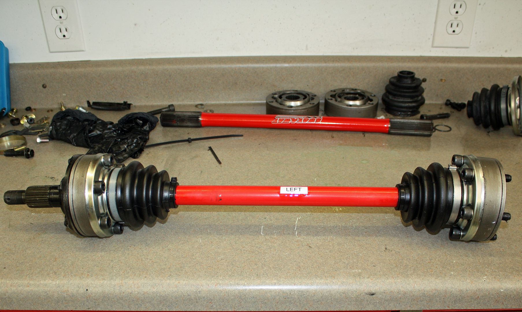
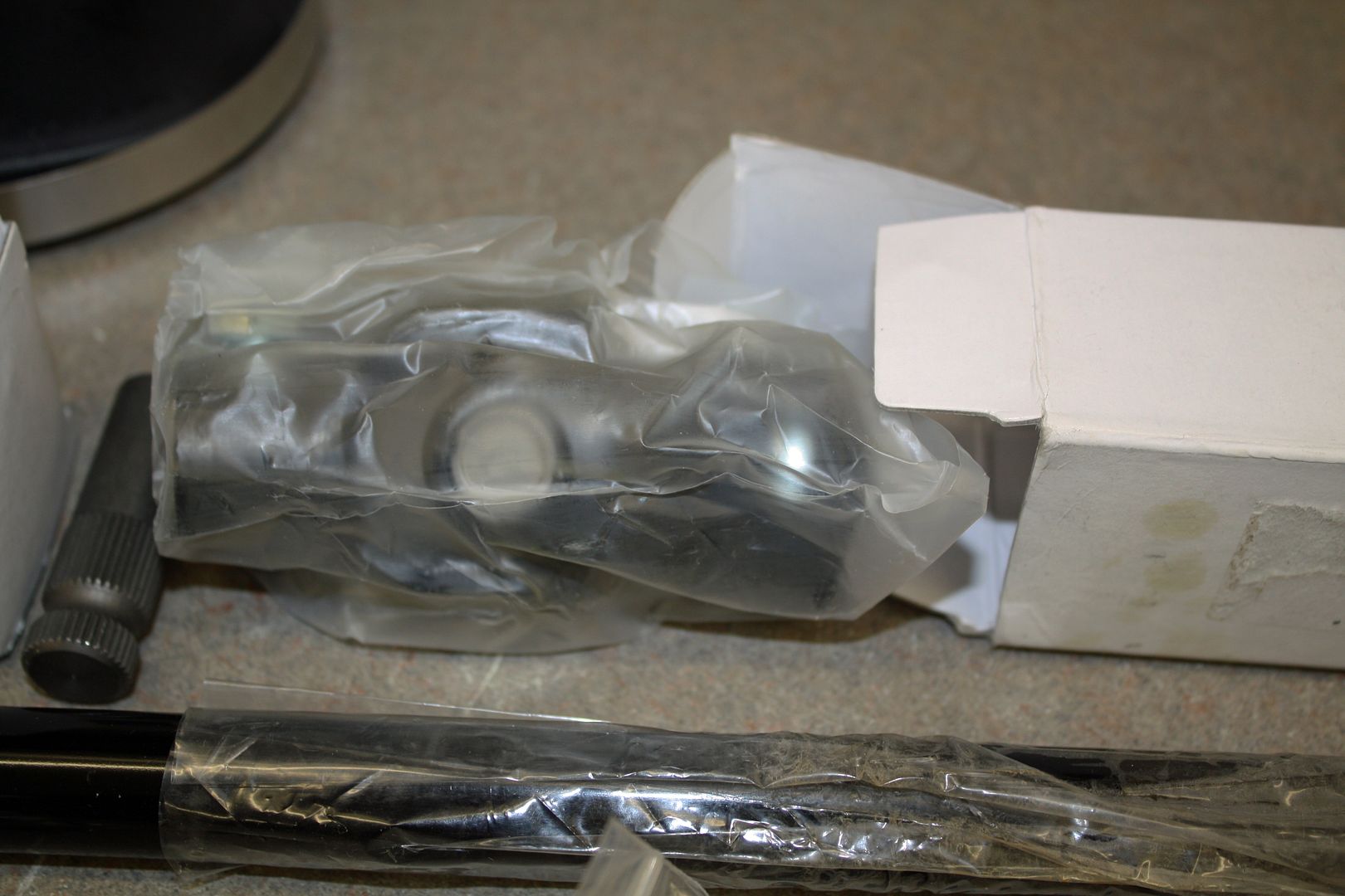
The Sway-Away axles are marked as left and right. According to their instructions, it doesn't matter which end goes to the transmission as long as the axles are used on the correct side of the car. As you can see, they have much longer splines and are designed to slide back and forth as needed. They are also quite a bit longer than the 911 axles.
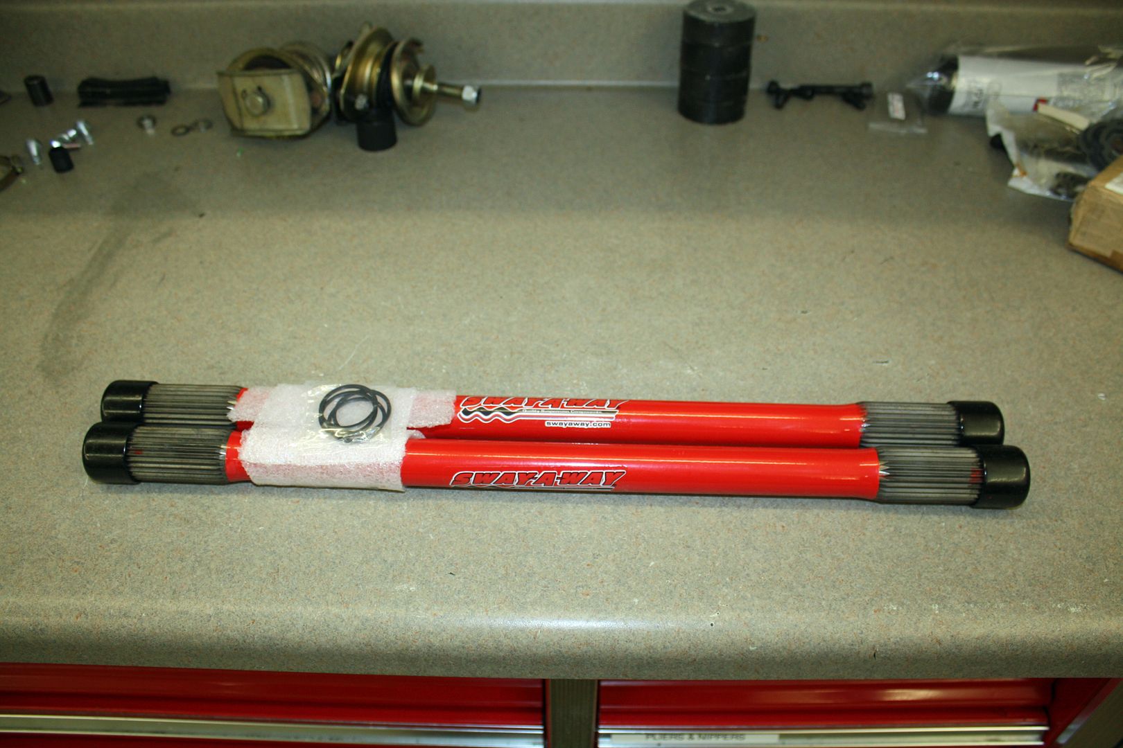
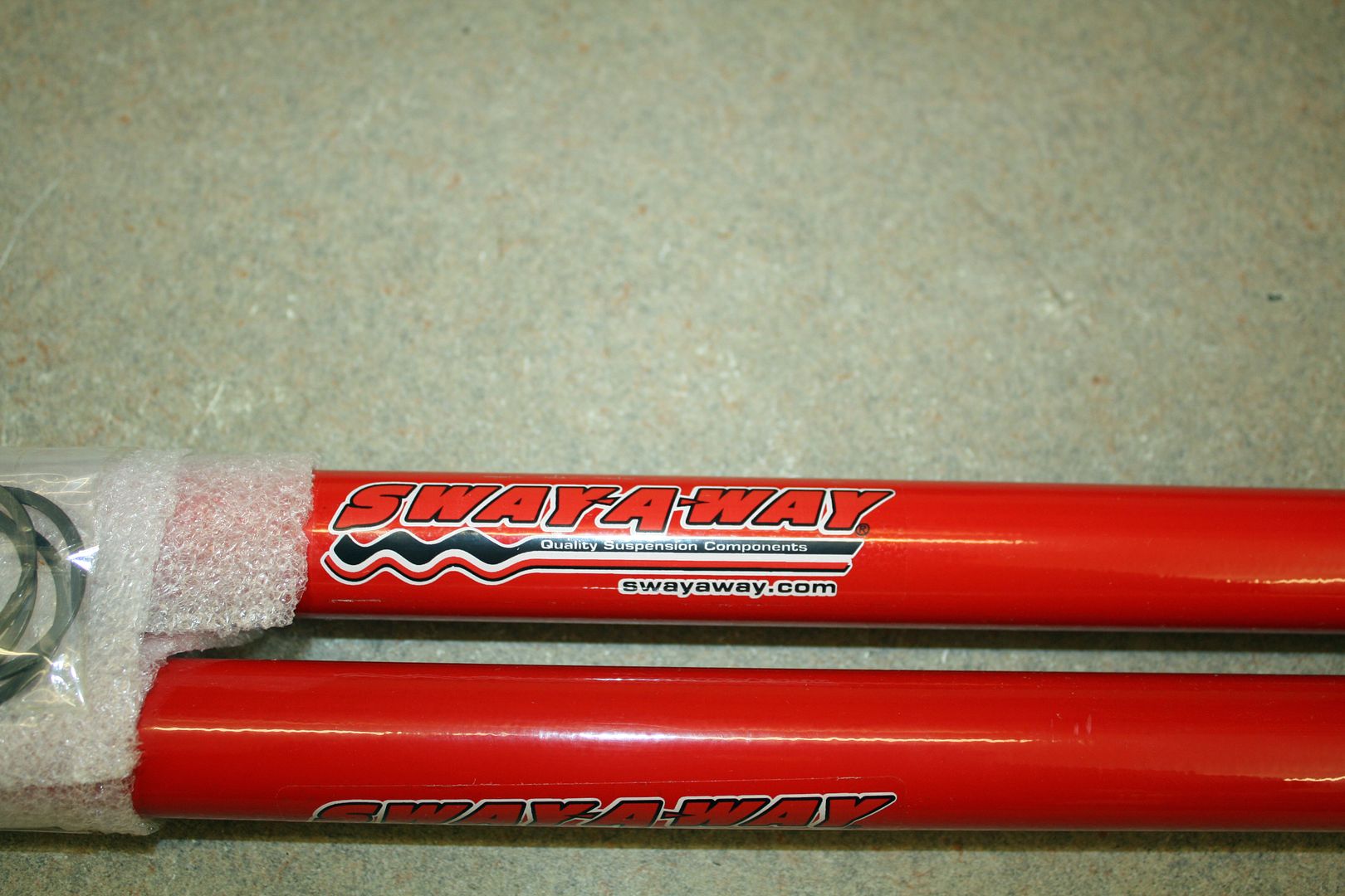
I am waiting for the CV bolts to arrive. Once they are here, I will pack the CV joints and mount everything to each axle. Then I can bolt the CV to the outer flange at the hub. Once that is done, I will be ready to put the engine back into the car.


I am waiting for the CV bolts to arrive. Once they are here, I will pack the CV joints and mount everything to each axle. Then I can bolt the CV to the outer flange at the hub. Once that is done, I will be ready to put the engine back into the car.
11-26-2018, 05:51 PM
#113
Racer
Thread Starter
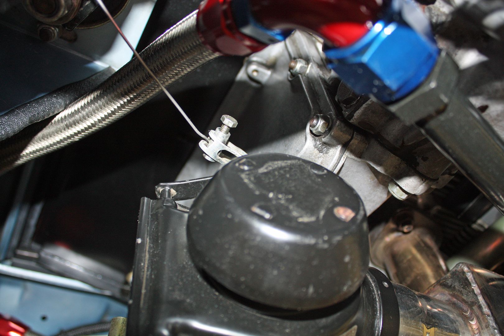
Yesterday morning, I spent some time on the throttle body linkage after reading Lucky9146's thread. Later in the day, I discovered that I had reversed the solid rod from the throttle to the transmission and had it upside down.
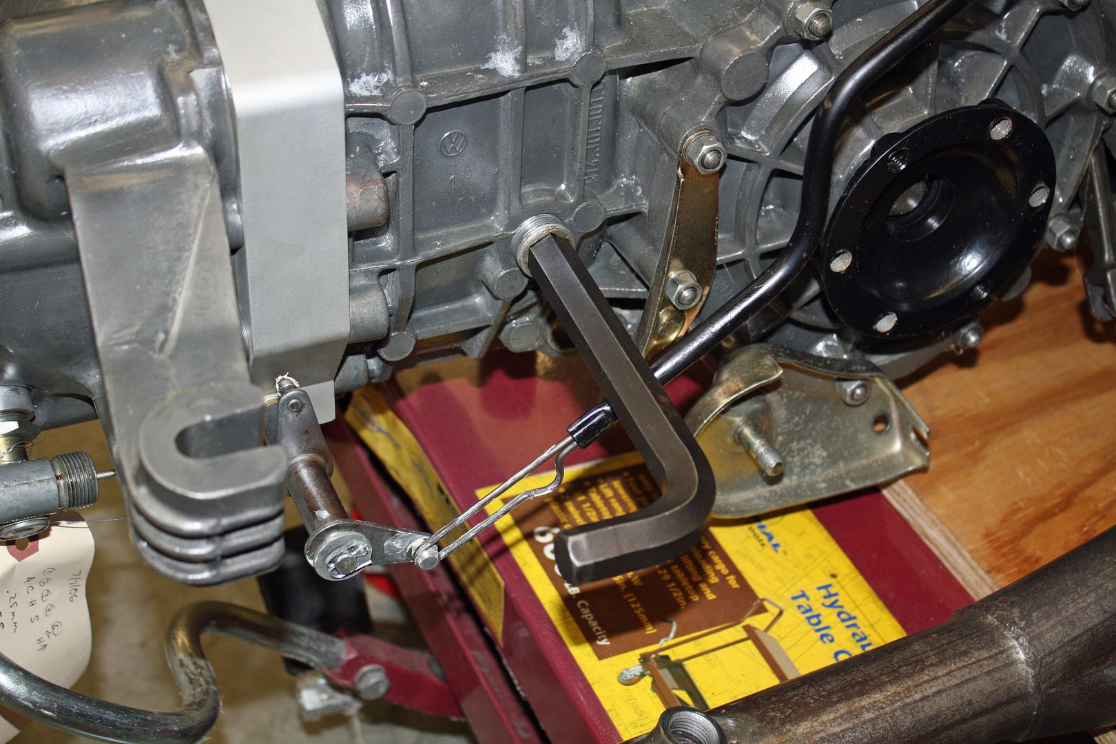
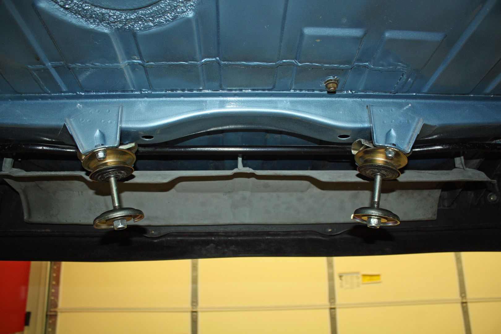
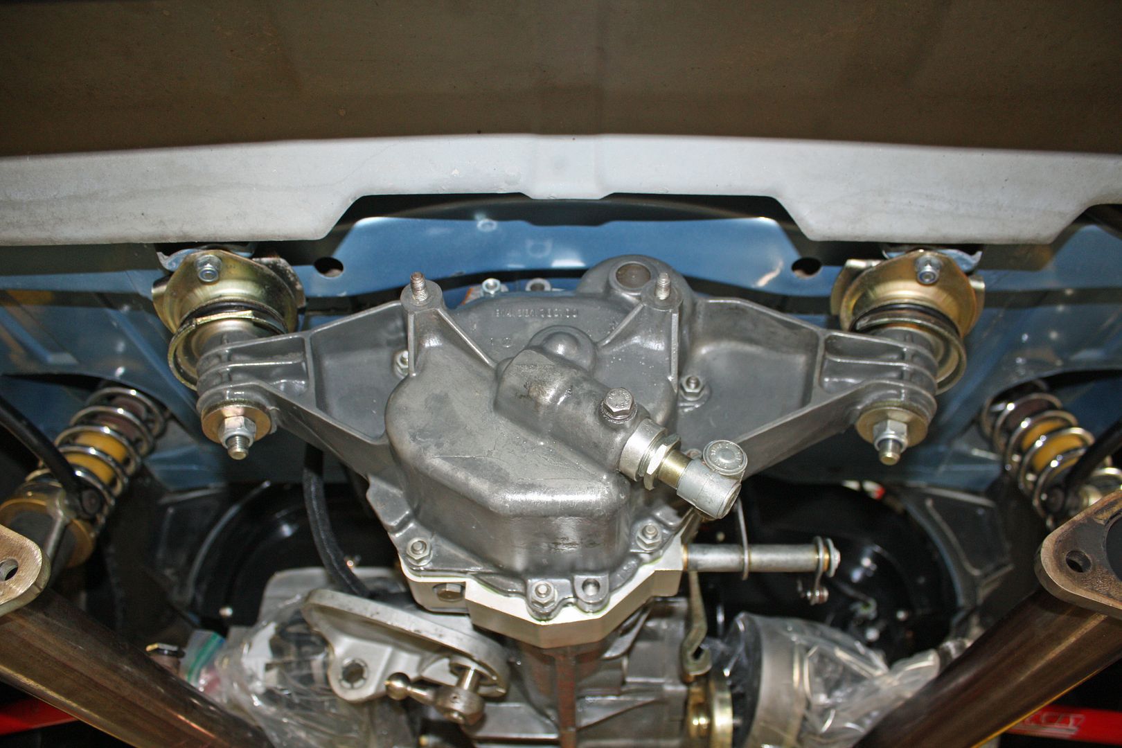
In anticipation of installing the engine, I installed the transmission mounts.
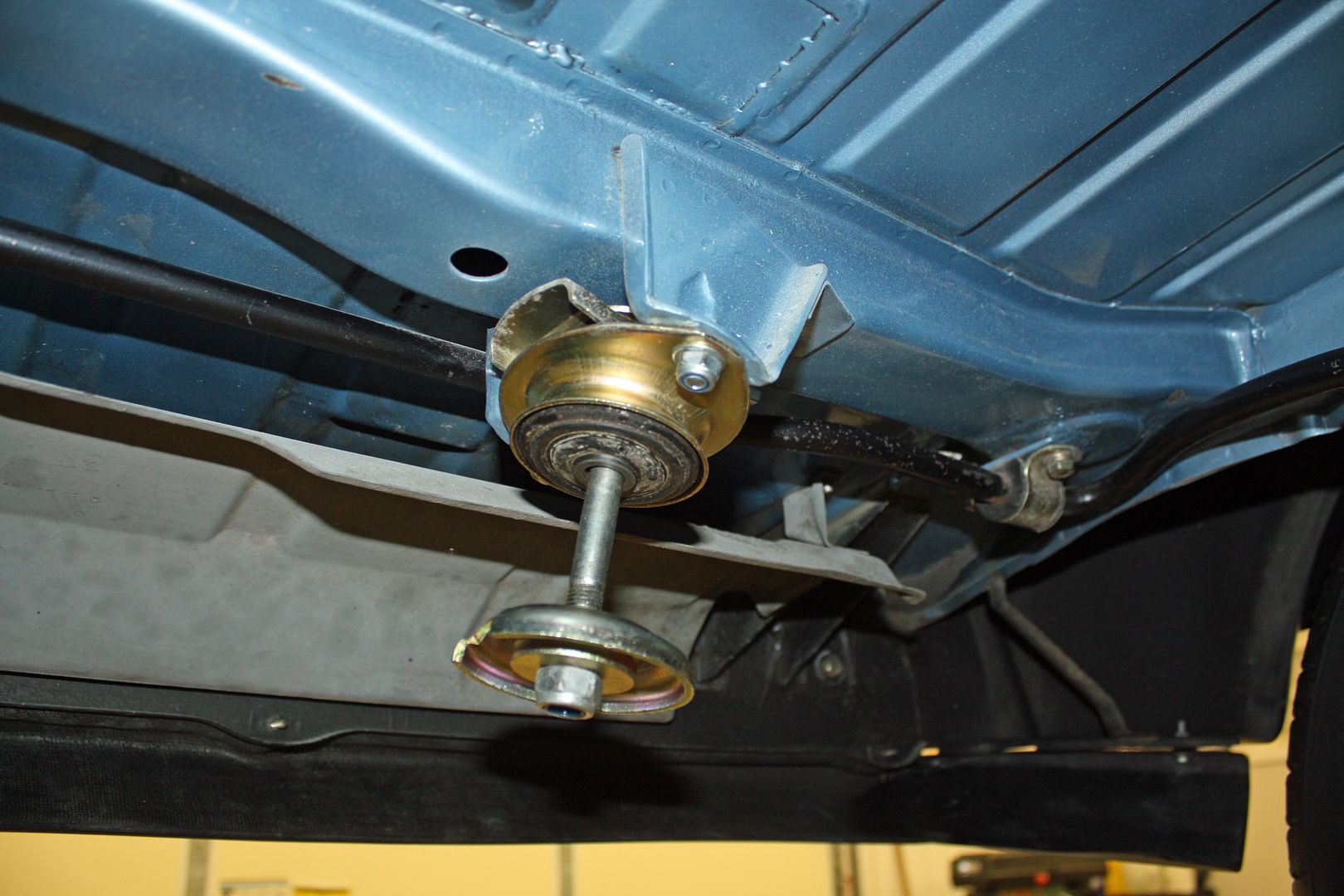
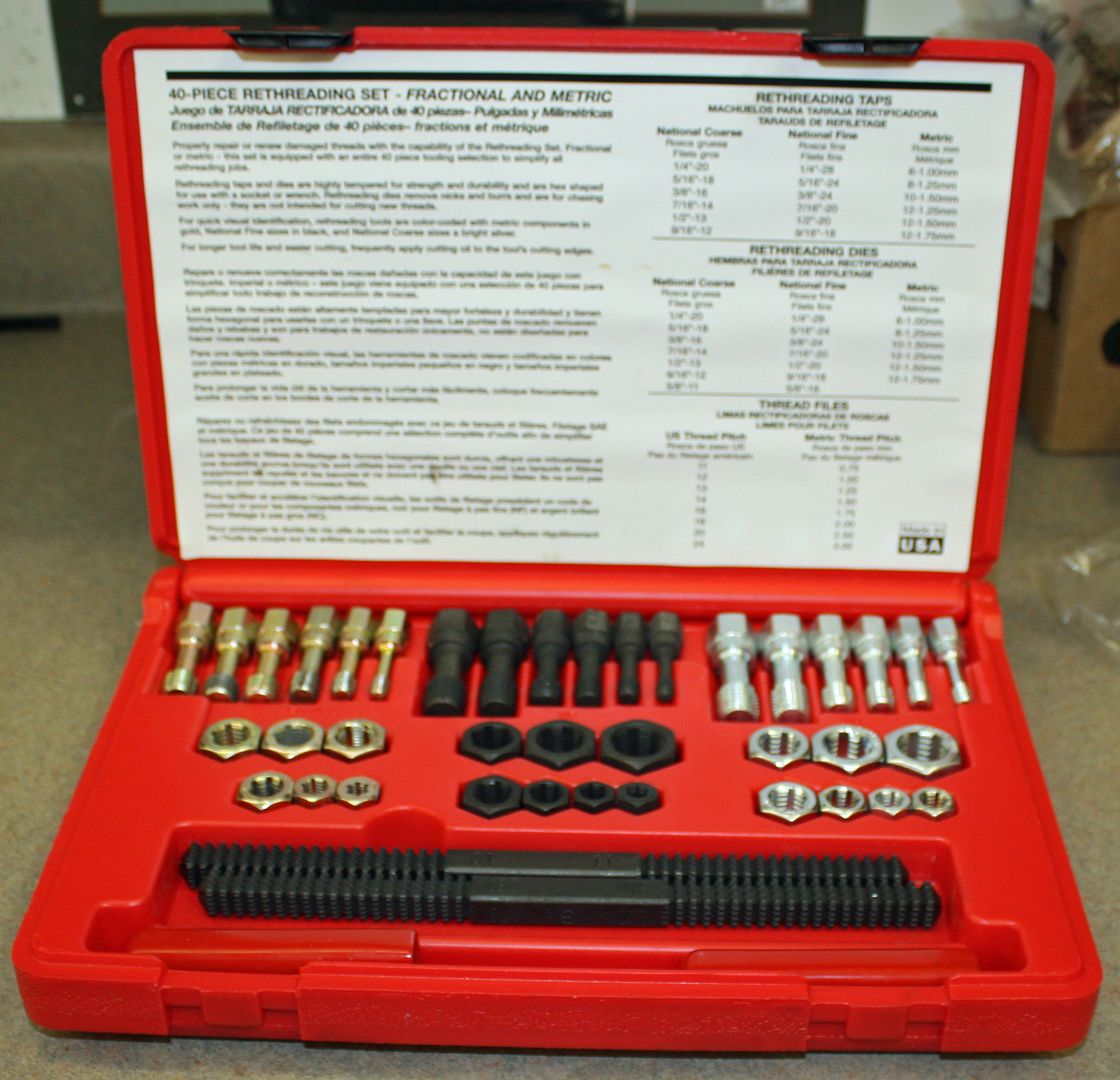
I also used my rethreader kit to clean out the threads on the output flanges on the transmission.
I had removed the passenger seat so that I could get to the firewall when I moved the fuel regulator. I wasn't happy with how the seats slid back and forth so I spent some time making sure the tracks were properly aligned. I also had not been able to get the driver's seat to go all the way back. Today I figured out why.
There was a rectangular plate, about the thickness of a washer, with two bolt holes that fit into the track of the seat. I have seen these before on other Porsche's so I didn't think much about it. However, there were only two that came with the car and they were the only things different between the two seats. I removed them and, voila, the seat went all the way back. Amazing how such a small victory can be so satisfying!!
The only things keeping me from putting the engine back into the car are the CV bolts I have on order. My son was visiting yesterday (with his Tesla 911) and he mentioned that the local drive shaft shop may have those bolts. The made the axles and CV joints for his car. I will check that out tomorrow.
Two of my neighbors drove Matt's car yesterday and both were impressed with the acceleration and how civilized the car was to drive. My buddy Reese raved about how easy and smooth the car was to drive. He is a hot rodder and sees Matt's car as the future of hot rodding for the next generation. As with most of us baby boomers, the technology is beyond out skills but we can appreciate the work and craftsmanship that goes into doing an electric car. After driving Matt's car, I can more readily see my daily driver being an electric car.
In anticipation of installing the engine, I installed the transmission mounts.
I also used my rethreader kit to clean out the threads on the output flanges on the transmission.


I had removed the passenger seat so that I could get to the firewall when I moved the fuel regulator. I wasn't happy with how the seats slid back and forth so I spent some time making sure the tracks were properly aligned. I also had not been able to get the driver's seat to go all the way back. Today I figured out why.
There was a rectangular plate, about the thickness of a washer, with two bolt holes that fit into the track of the seat. I have seen these before on other Porsche's so I didn't think much about it. However, there were only two that came with the car and they were the only things different between the two seats. I removed them and, voila, the seat went all the way back. Amazing how such a small victory can be so satisfying!!
The only things keeping me from putting the engine back into the car are the CV bolts I have on order. My son was visiting yesterday (with his Tesla 911) and he mentioned that the local drive shaft shop may have those bolts. The made the axles and CV joints for his car. I will check that out tomorrow.
Two of my neighbors drove Matt's car yesterday and both were impressed with the acceleration and how civilized the car was to drive. My buddy Reese raved about how easy and smooth the car was to drive. He is a hot rodder and sees Matt's car as the future of hot rodding for the next generation. As with most of us baby boomers, the technology is beyond out skills but we can appreciate the work and craftsmanship that goes into doing an electric car. After driving Matt's car, I can more readily see my daily driver being an electric car.
11-27-2018, 04:53 PM
#114
Racer
Thread Starter
With the help of a tip about the incorrect placement of the top part of the transmission mount, I rectified that today.
My son was correct in that The Driveshaft Shop had the correct M10 1.5x50mm CV bolts. I picked them up this morning. This afternoon, I assembled the left axle. I began by removing the flange from the rear trailing arm. I then chased the threads and applied the gasket.
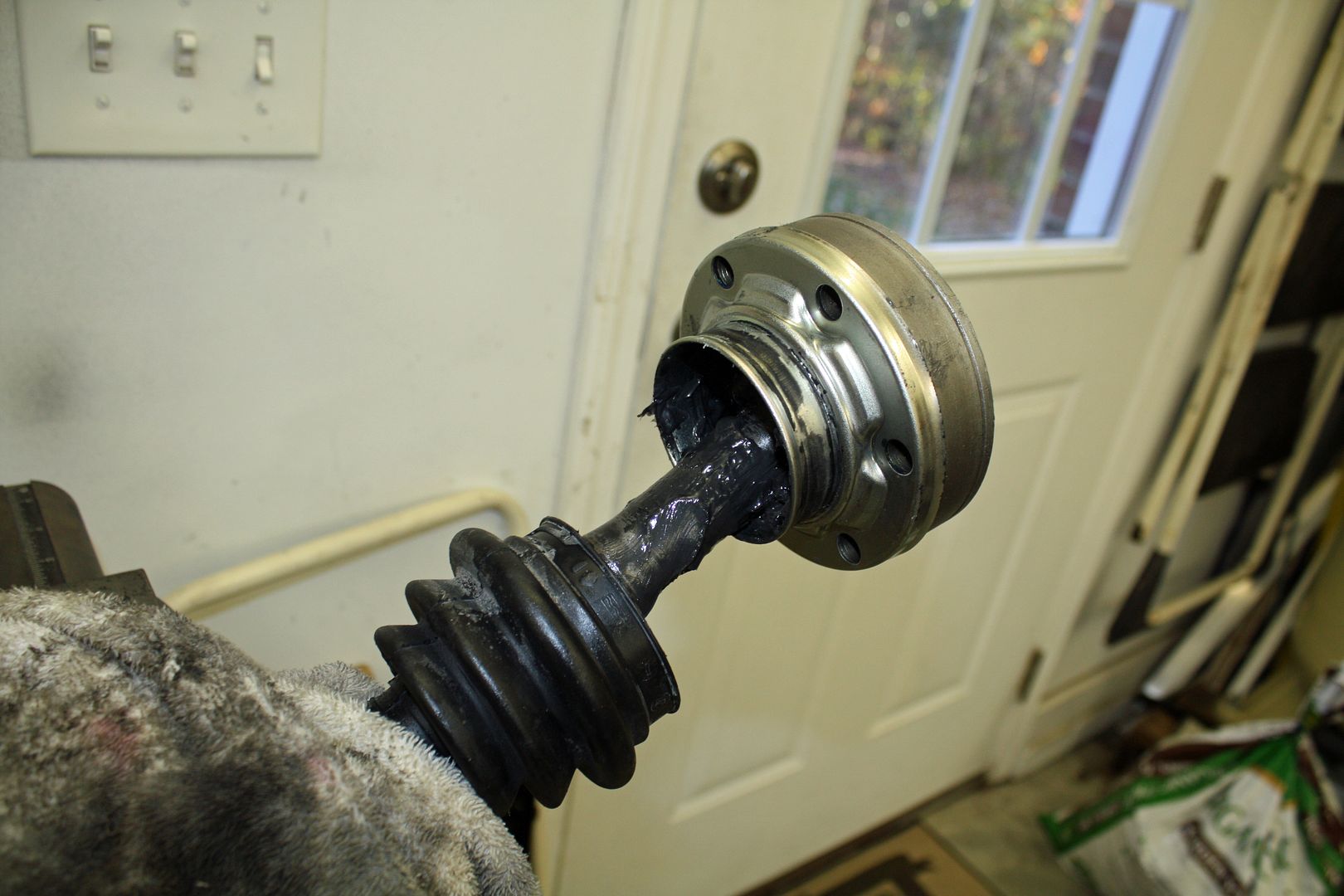
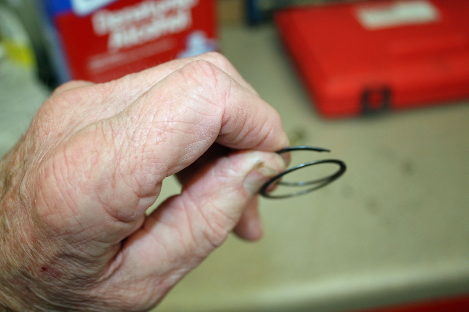
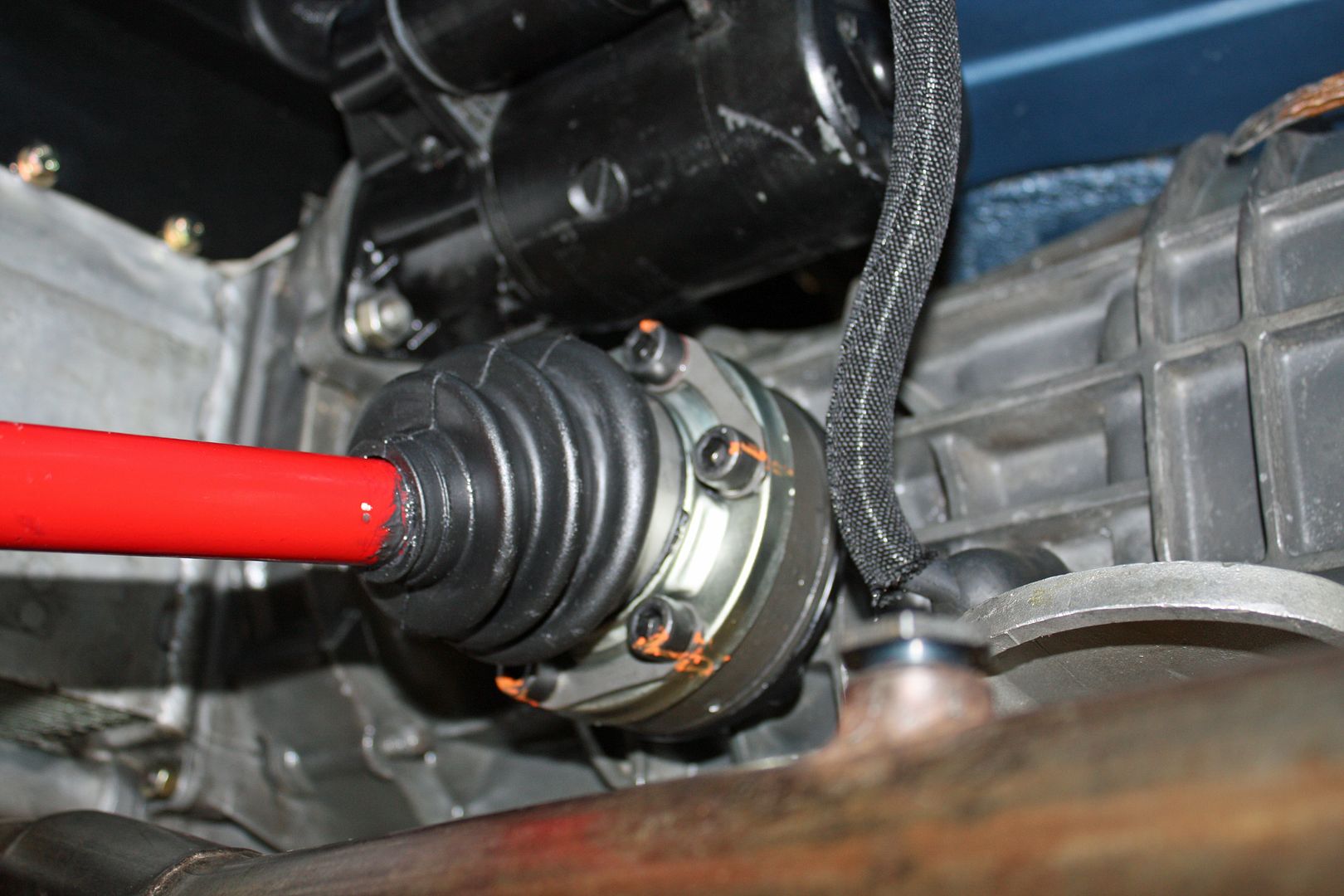
After placing the boot on the axle, placing lots of grease in it and in the CV joint, I slid the joint on the axle. Instead of a snap ring at the end of the axle, this one used a type of ring that you basically spread out and then screw it onto the axle.
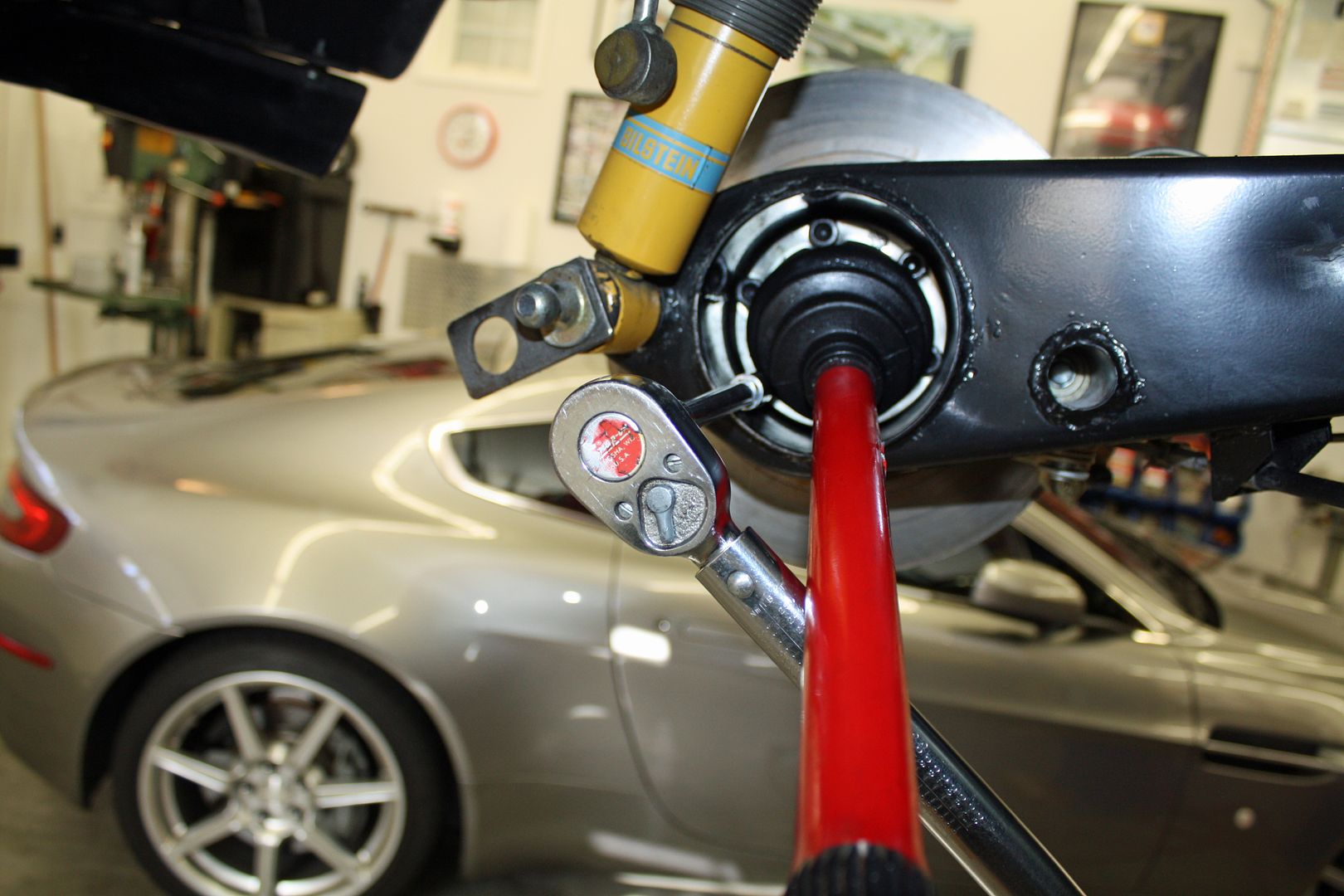
With that in place, I bolted the CV to the flange using the bolts with a schnoor washer. I had to insert the flange in the trailing arm and apply the parking brake so I could torque the bolts to 34ft lb.
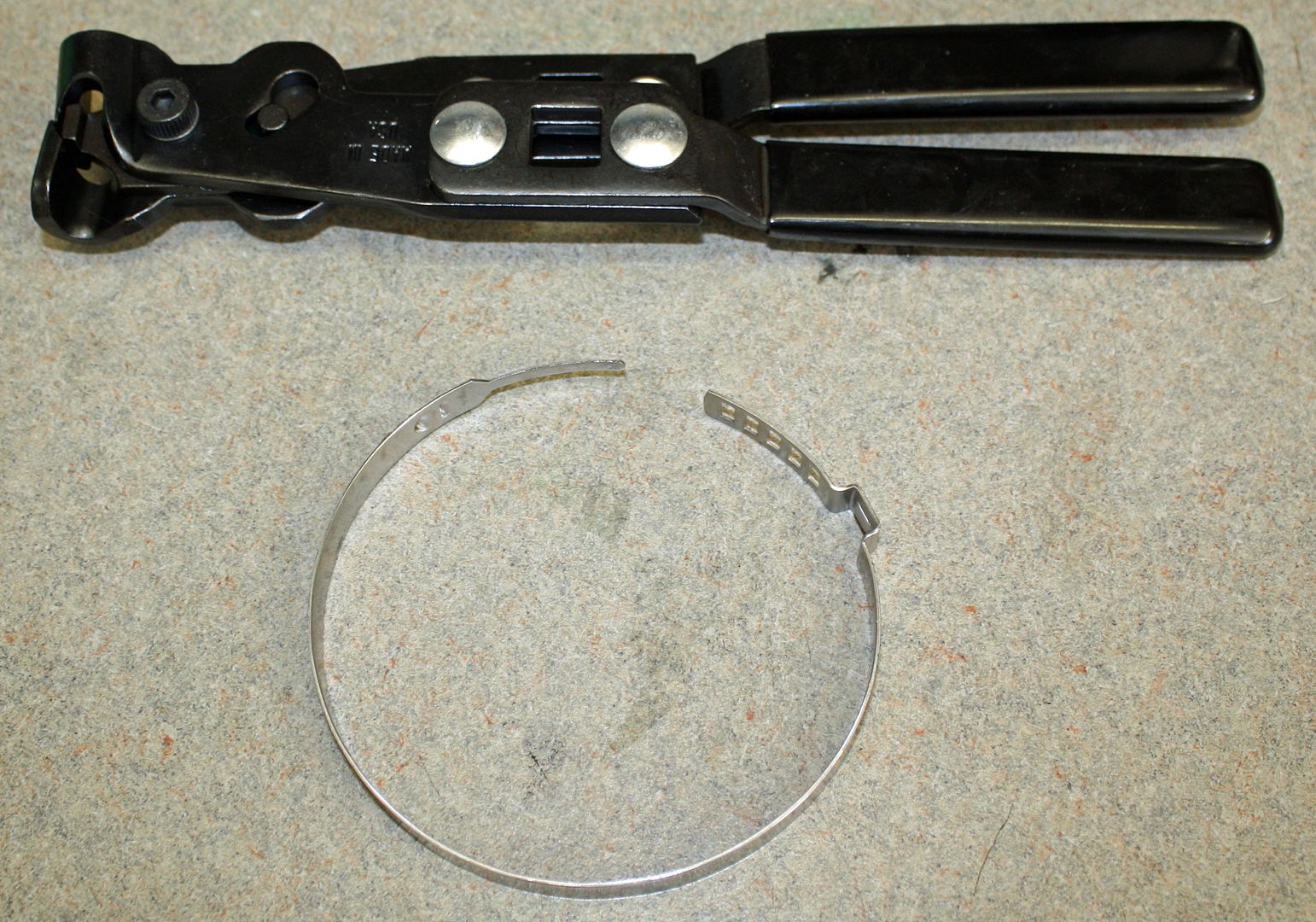
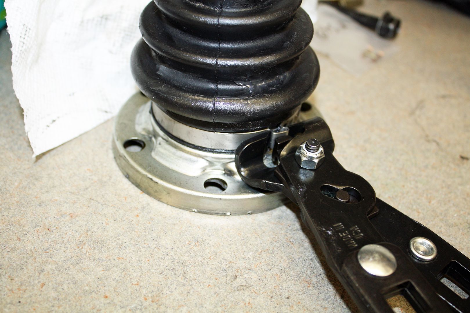
After removing the axle from the car, I assembled the CV joint on the other end. Since I had separated the boot from the flange, I had to re-install it using a crimp style hose clamp with a pinch crimper.
With everything installed, I cleaned up the axle and boots. Since these axles are marked left and right, I ran off a "Left" label and applied it to the axle. Again I robbed my wife's clear finger nail polish to permanently secure the label to the axle.
Tomorrow I will assemble the right axle, install both of them in the car and get ready for the engine installation. Getting very close now!!
My son was correct in that The Driveshaft Shop had the correct M10 1.5x50mm CV bolts. I picked them up this morning. This afternoon, I assembled the left axle. I began by removing the flange from the rear trailing arm. I then chased the threads and applied the gasket.

After placing the boot on the axle, placing lots of grease in it and in the CV joint, I slid the joint on the axle. Instead of a snap ring at the end of the axle, this one used a type of ring that you basically spread out and then screw it onto the axle.


With that in place, I bolted the CV to the flange using the bolts with a schnoor washer. I had to insert the flange in the trailing arm and apply the parking brake so I could torque the bolts to 34ft lb.


After removing the axle from the car, I assembled the CV joint on the other end. Since I had separated the boot from the flange, I had to re-install it using a crimp style hose clamp with a pinch crimper.


With everything installed, I cleaned up the axle and boots. Since these axles are marked left and right, I ran off a "Left" label and applied it to the axle. Again I robbed my wife's clear finger nail polish to permanently secure the label to the axle.

Tomorrow I will assemble the right axle, install both of them in the car and get ready for the engine installation. Getting very close now!!
11-28-2018, 04:42 PM
#115
Racer
Thread Starter
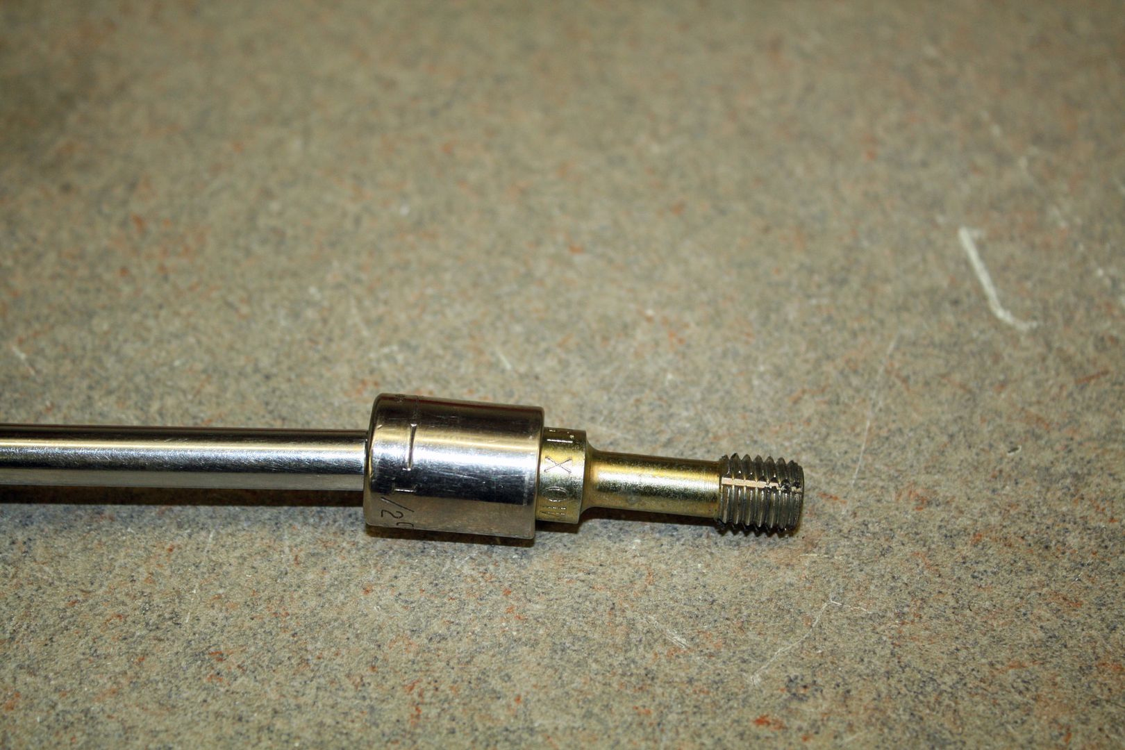
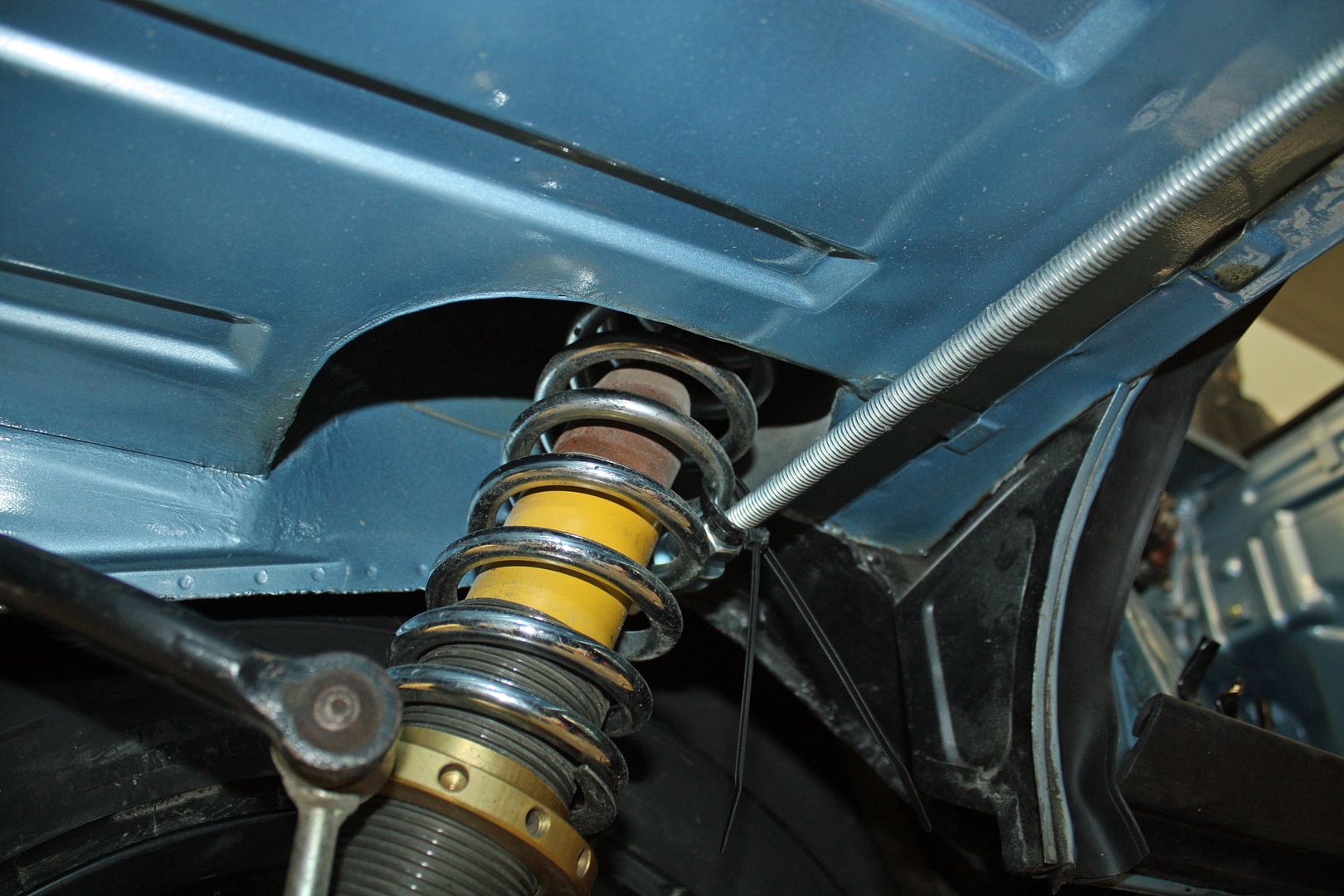
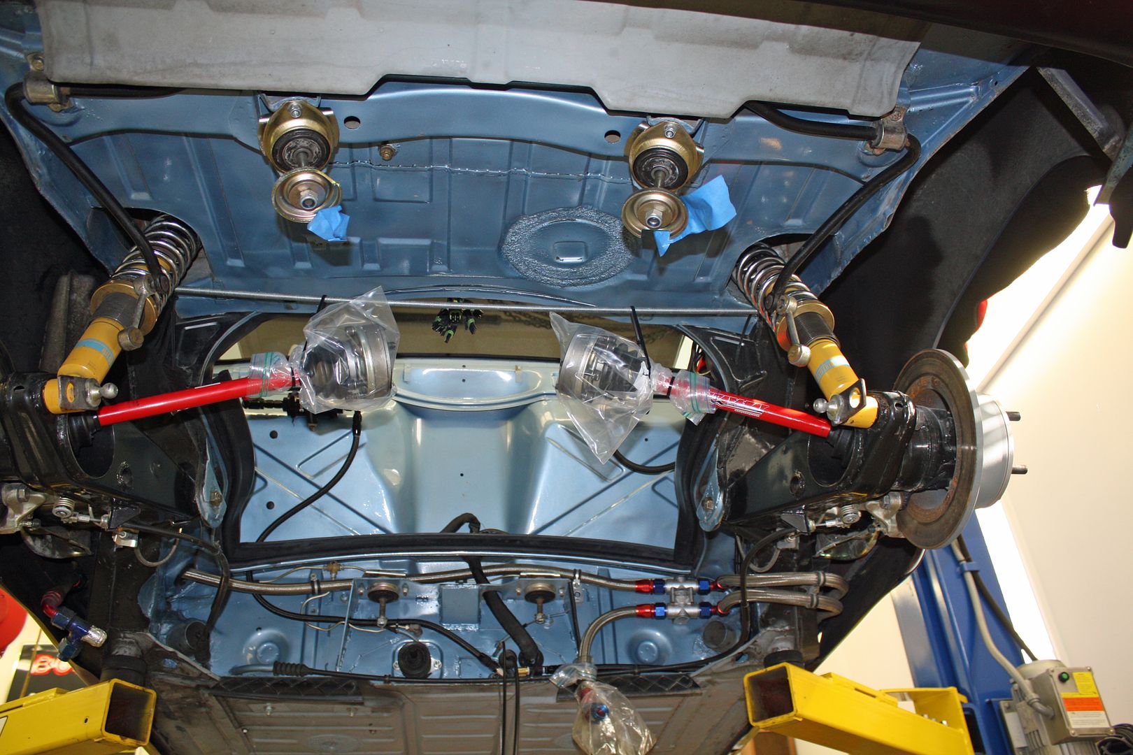
I finished up the right axle today. In Lucky9146's thread, I saw that he used a piece of conduit run from one shock to the other as a place to tie up the axles. I had a piece of threaded rod that was the right length and tied the axles to it.
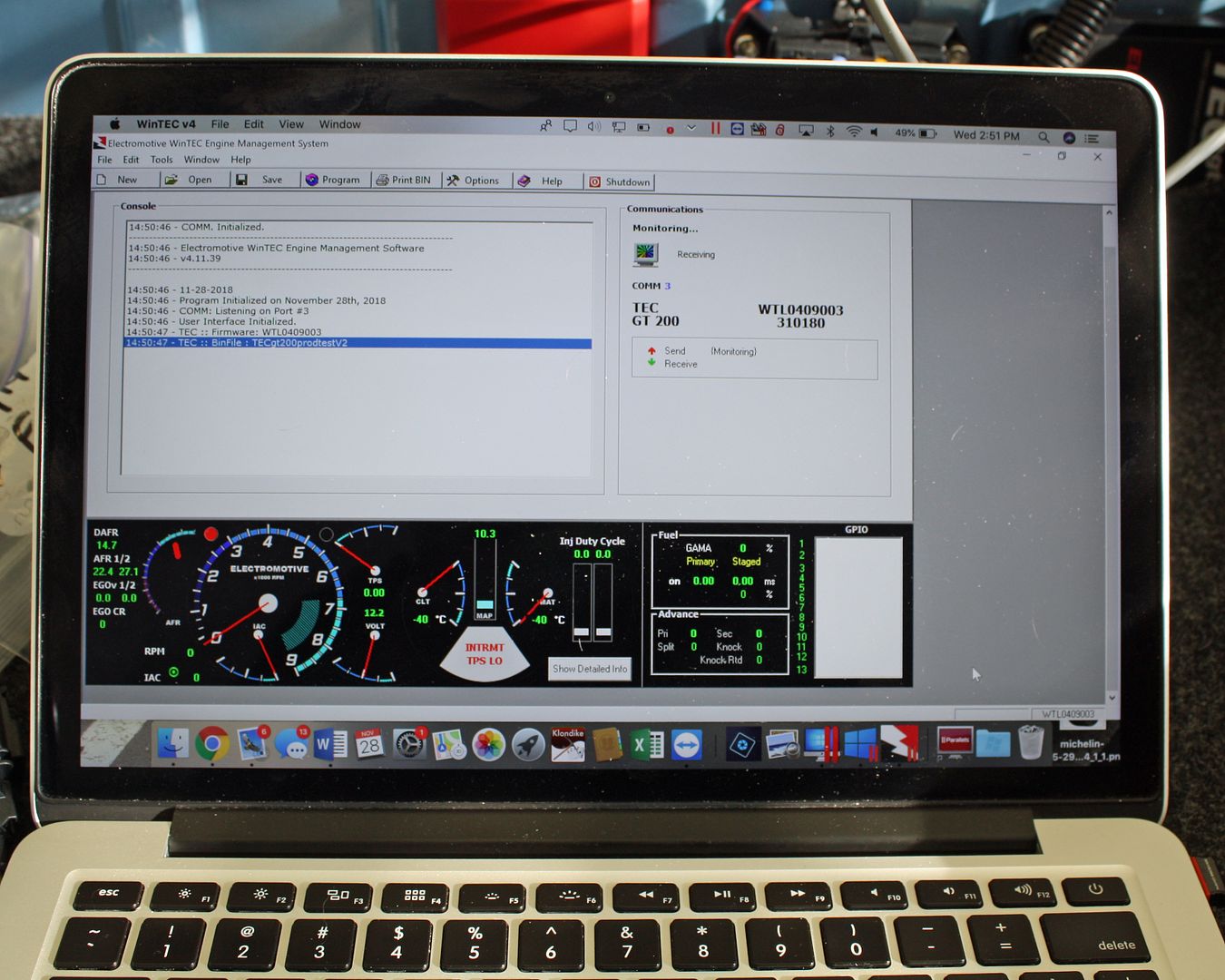
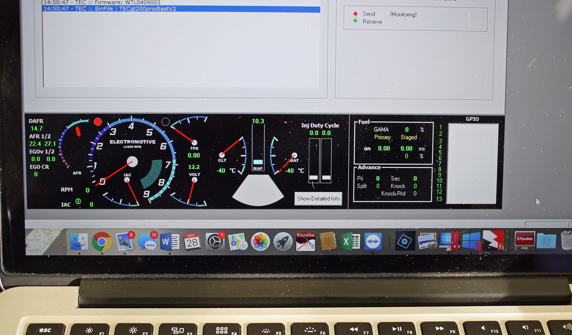
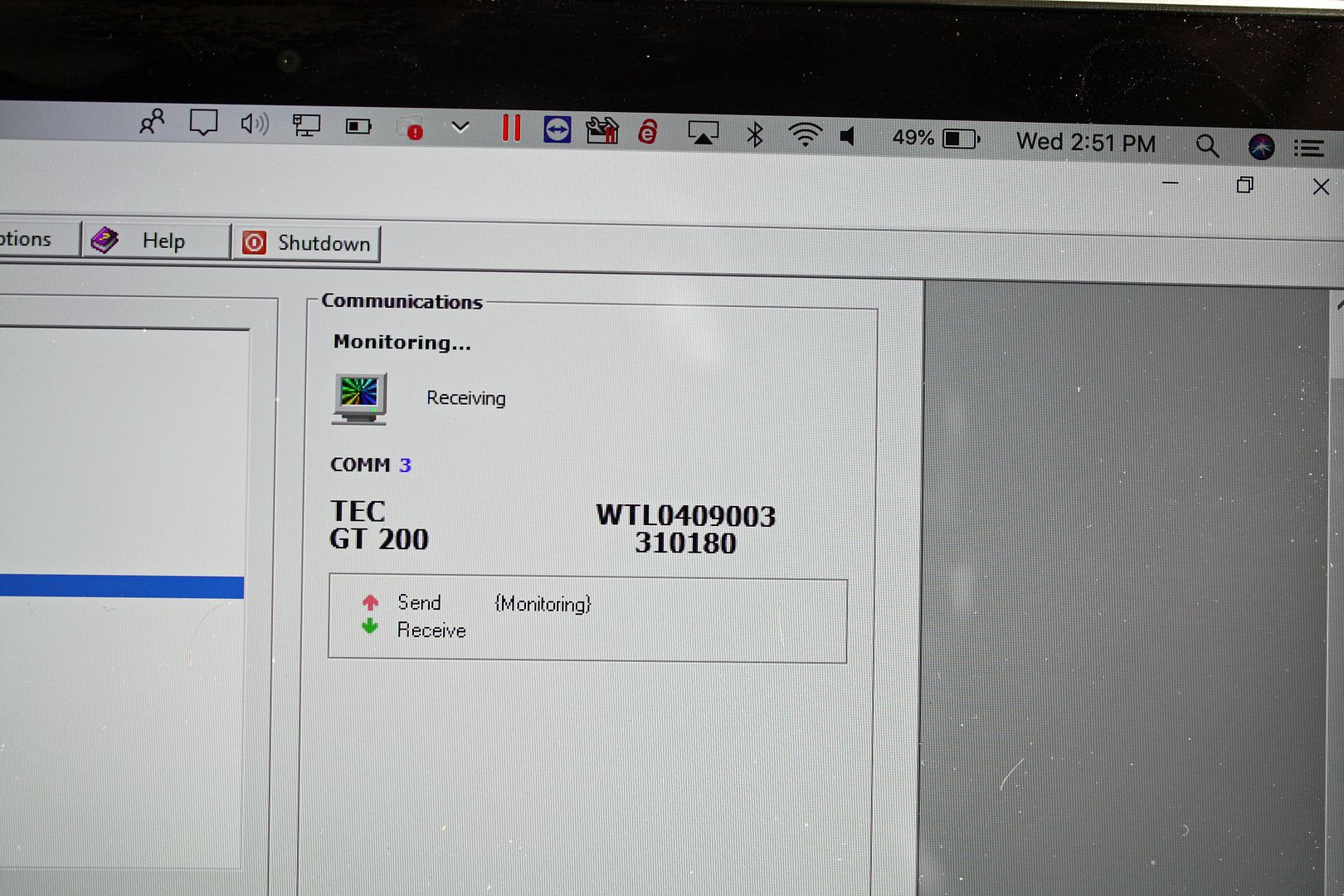
I found the courage to hook up the power to the ECU. Electromotive's software for the Wintec GT200 only works with Windows. I asked my son if I could borrow his laptop when the time came to plug into a computer. He told me about a program called Parallels that would allow me to install Windows on my MacPro. The program worked as he said it would. I fired up the program, plugged the USB cord, and turned on the ignition. And I was rewarded with the program finding the ECU!! That was a relief.
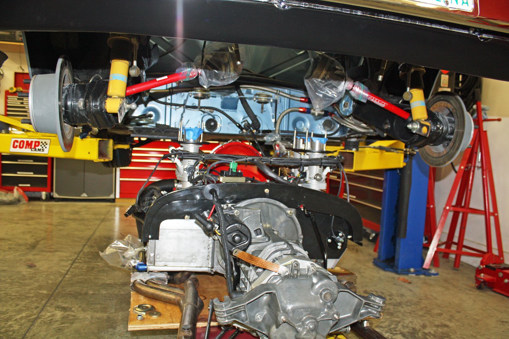
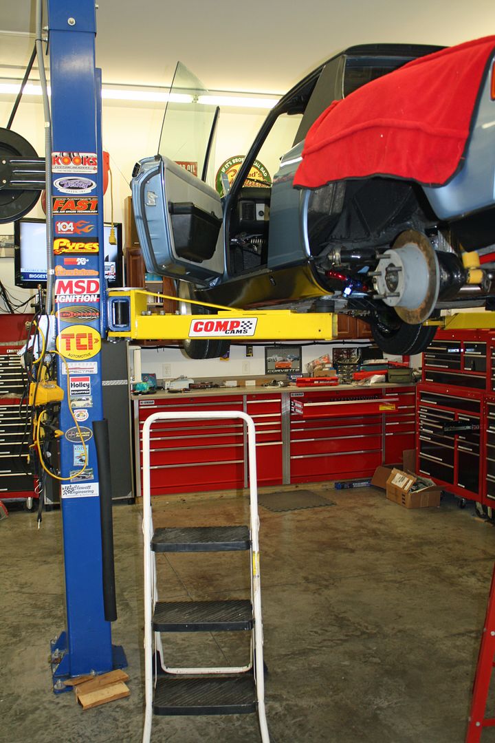
I rolled the motor and tranny under the car. My buddy Reese will be here tomorrow at 9:00 and we will see about getting this bad boy into the car!!! Prayers would be appreciated!!

 11-29-2018, 05:35 PM
#116
Racer
Thread Starter
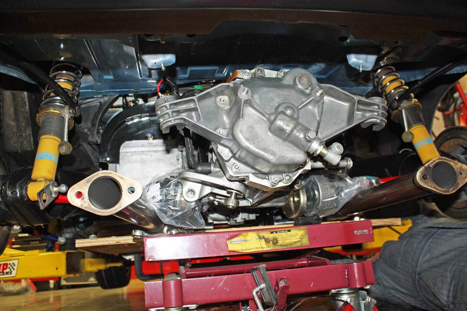
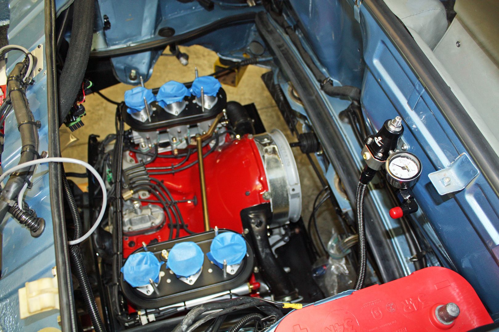
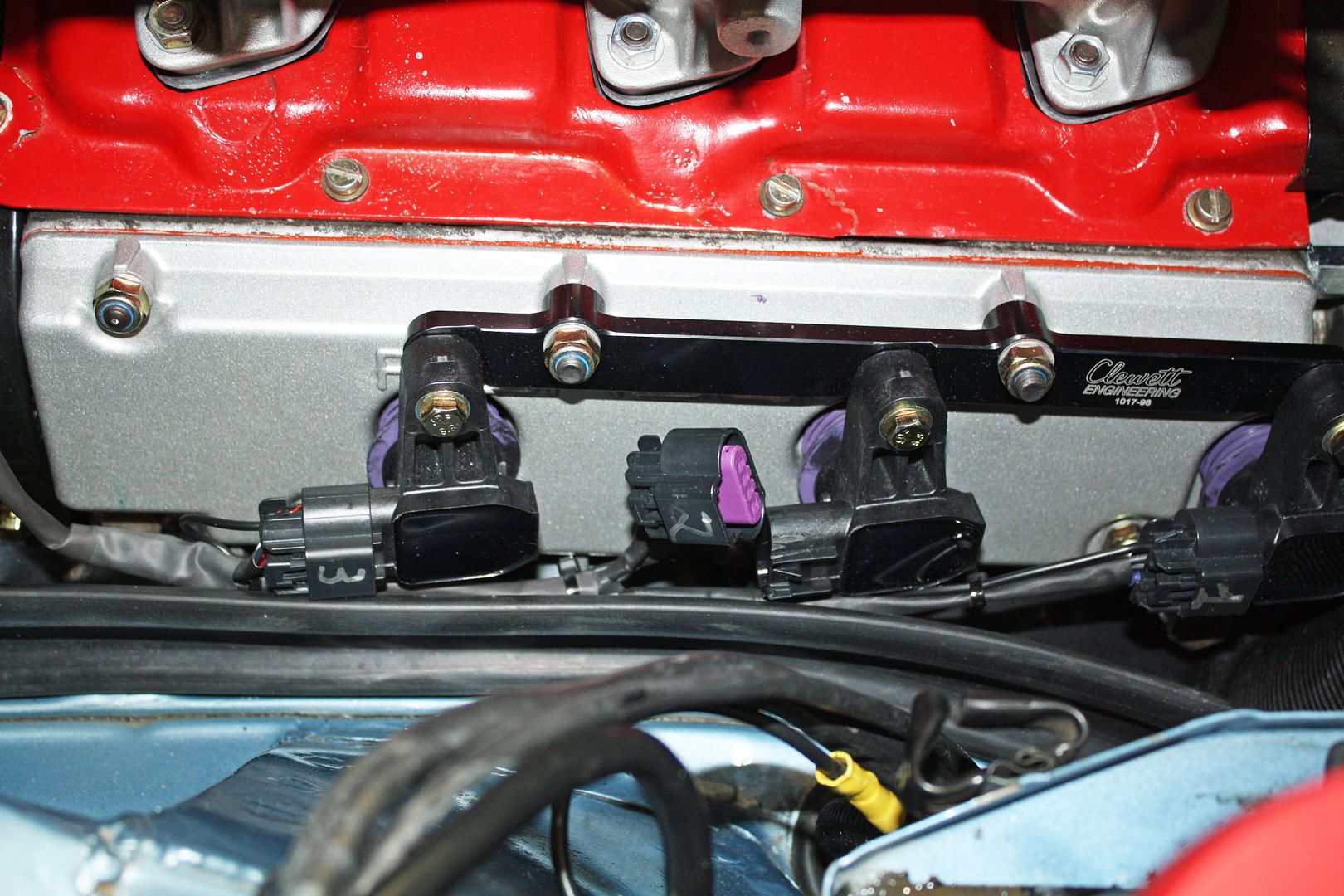
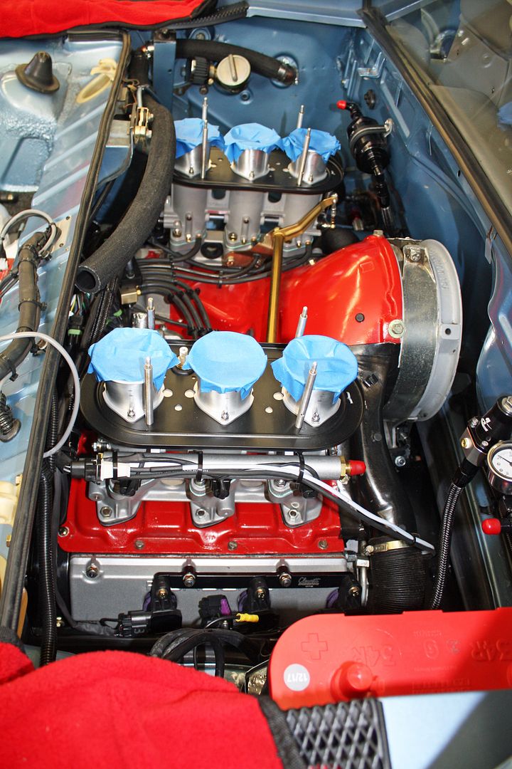
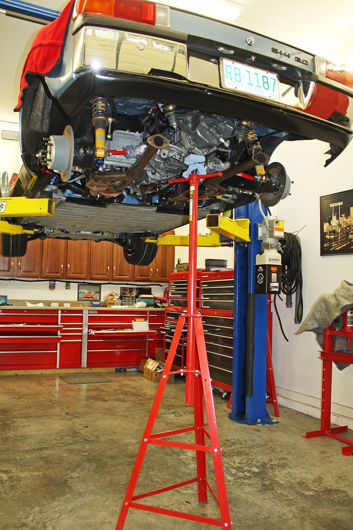
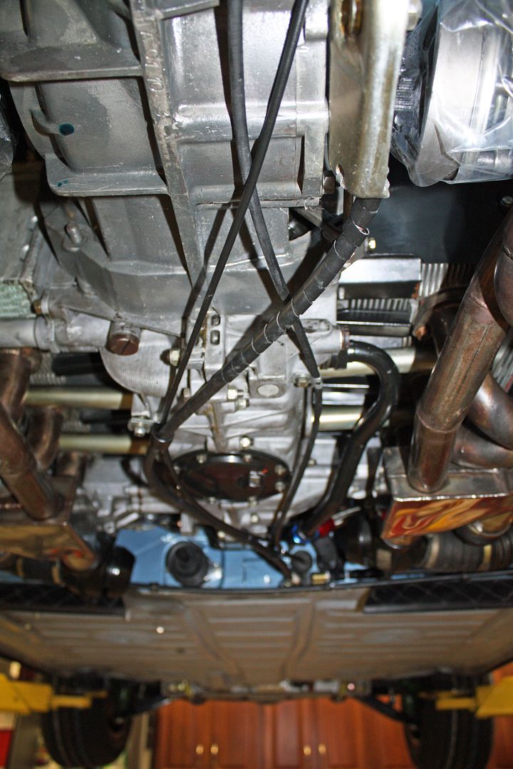
The engine is in!!! Took the two of us a couple hours to finagle it into position. It was really close on each side at the upper shock bolt. The tin in those areas was bent previously in that area and now I know why. But the plus side is that we knew we had th engine centered in the engine bay as it was rubbing on both sides. I had to unplug the center COP connector for clearance. At the rear, we had to remove the transmission mounts and then re-mount it once we had the transmission closer to being in the proper place.


 11-29-2018, 07:19 PM
#117
Racer
Thread Starter
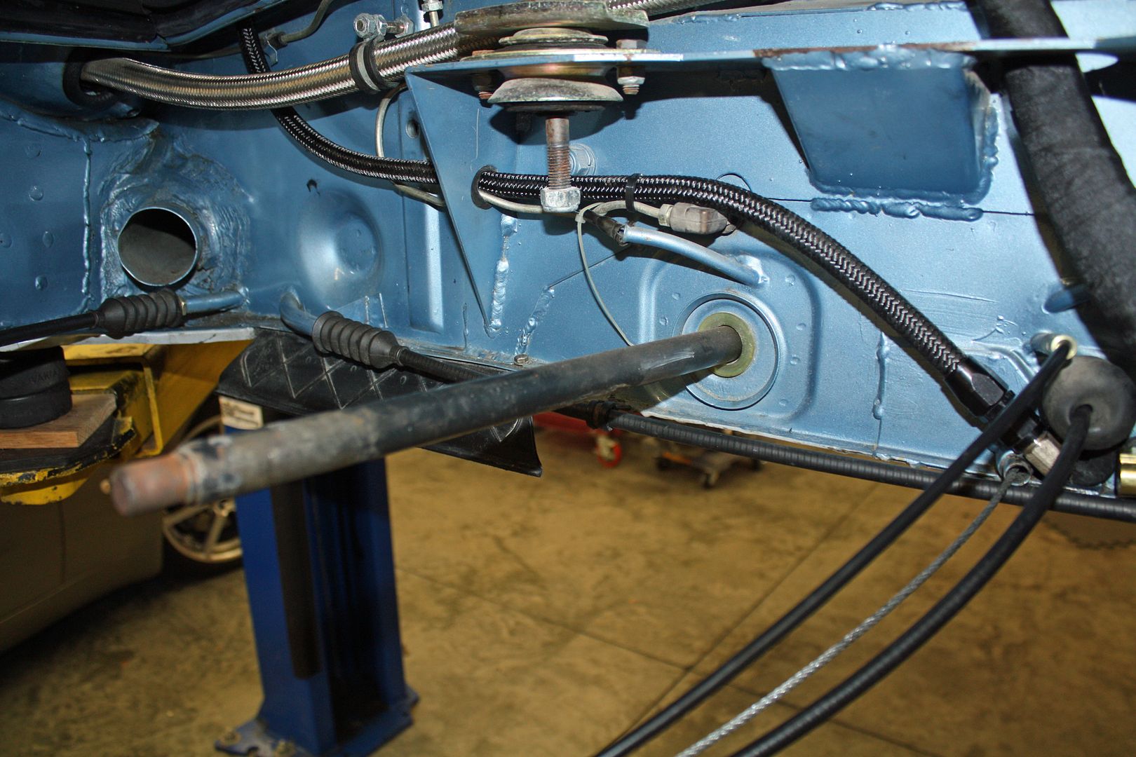
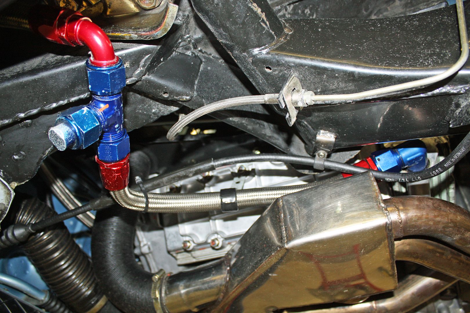
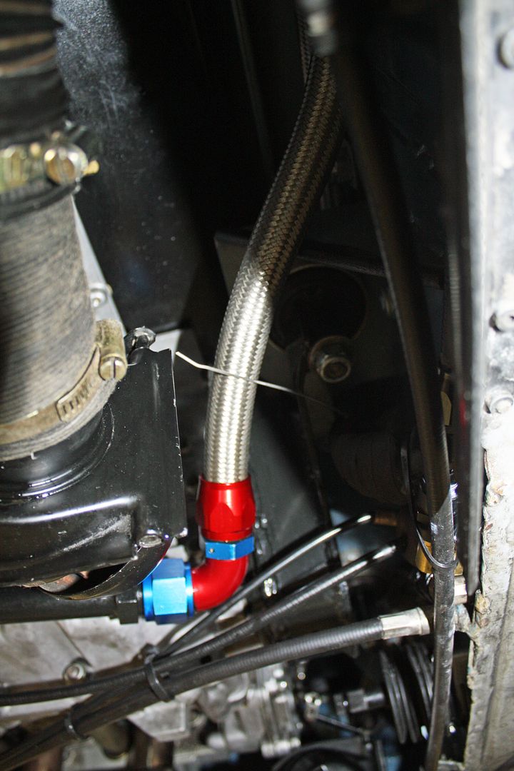
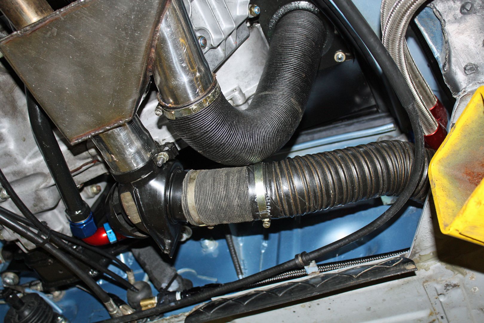
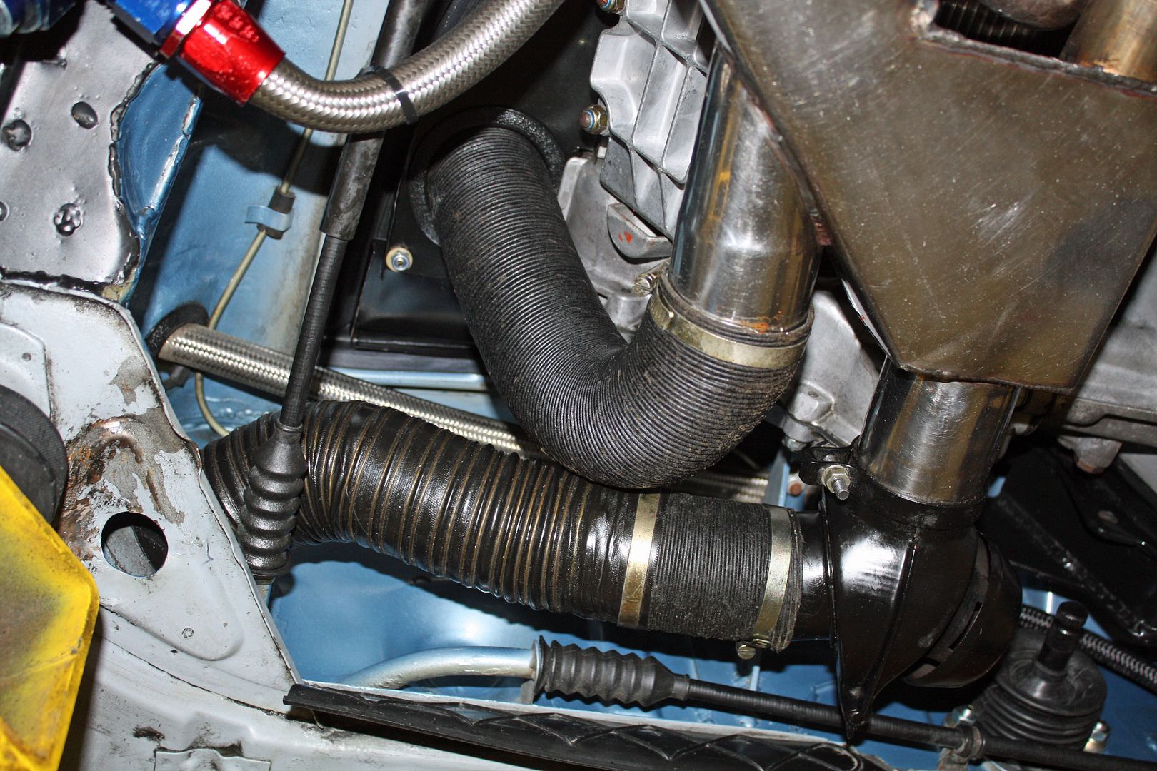
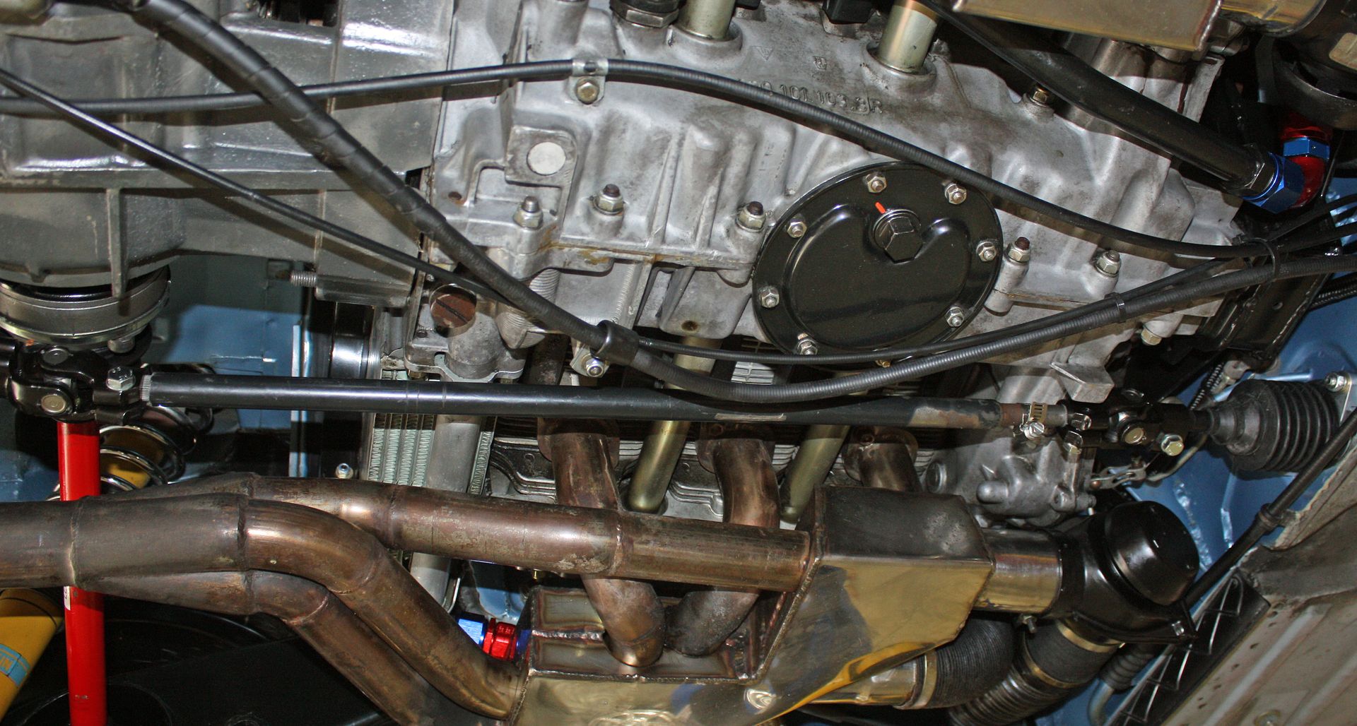
I worked this afternoon on hooking up things on the bottom of the motor. I did the oil lines, the heater hoses, and the cables for the accelerator, clutch and speedometer. Since I now had all of that weight on the rear of the car, I took the precaution of using one of my tall jack stands for safety's sake.


 12-01-2018, 05:29 PM
#118
Racer
Thread Starter
First thing yesterday I hooked up the heater cables.
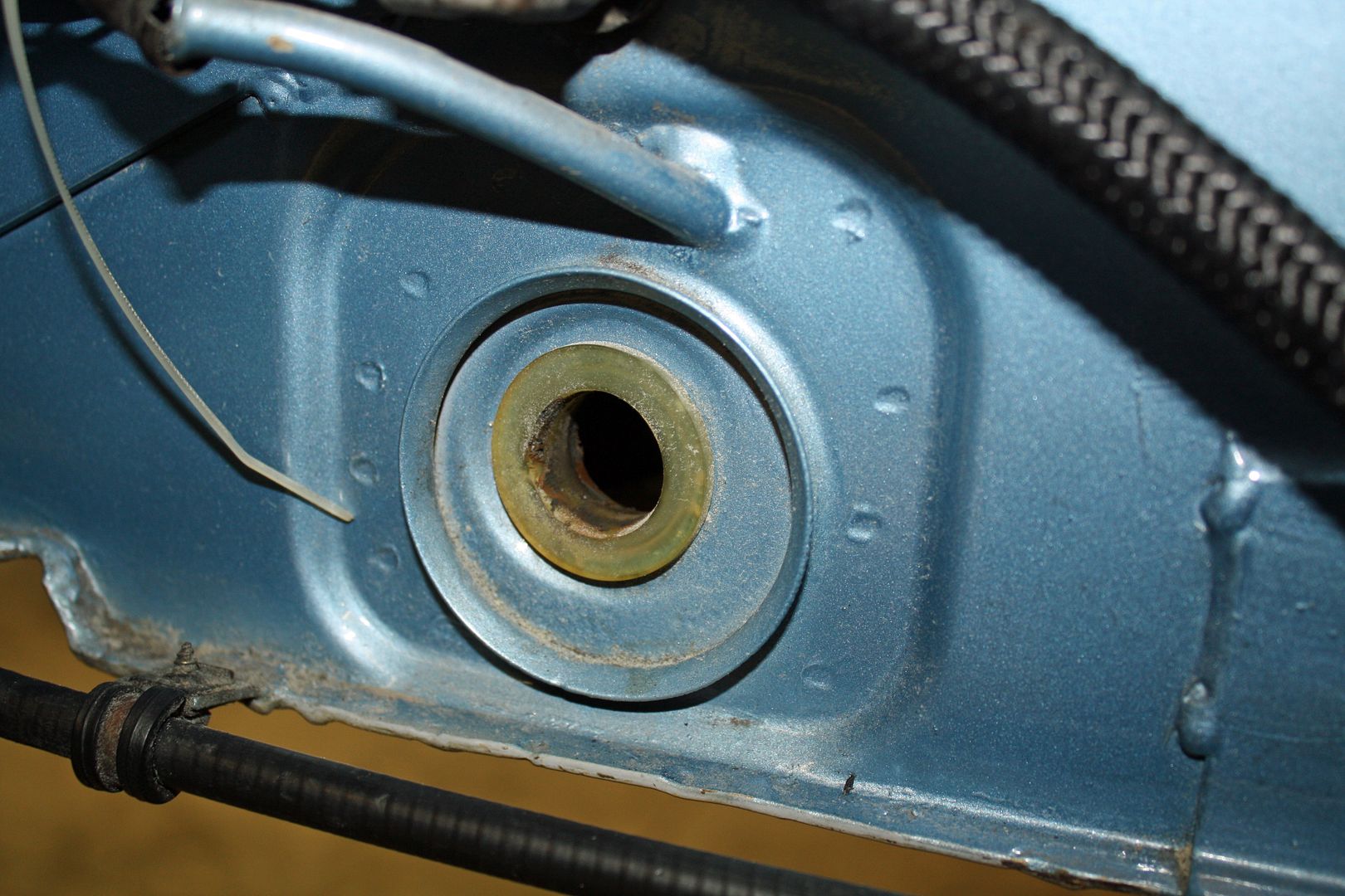
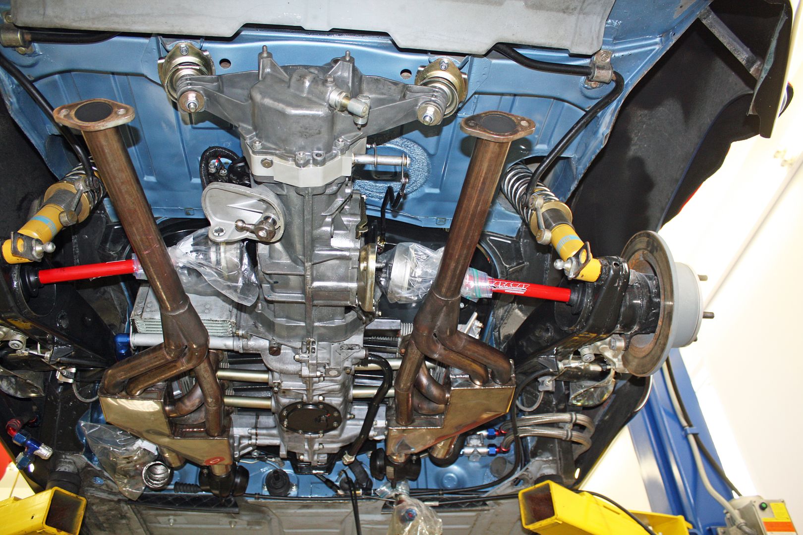
The day became more complicated once I began installing the axles. I had placed the axles in the trailing arms prior to installing the motor. I torqued the CV bolts and the main axle nut. Now I was ready to attach the CV's to the transmission flange. When I went to turn the hub to line up the CV bolt holes, it would not move. I checked to make sure the parking brake was off and it was. After considering things for a bit, I backed out the outer CV bolts and the hub would move. To test what bolt size would work, I placed some washers on the bolts to effectively make the bolts shorter. Even then, after trying different combinations of washers, I still was having an issue with everything locking up.
At this point I decided the axle had to come out of the trailing arm. There wasn't room to take the axle out with the CV joined to the flange so I separated them and pulled the axle out separately. With the axle out, I could see that there wasn't much clearance between the rear of the flange and the inside of the trailing arm and could see where the paint had been rubbed off when turning the flange with no axle attached. At this point I wasn't sure what to do. I wondered it I could shim the flange away from the inside of trailing arm.
To check on that, I called Chris Foley. He had never heard of someone having this issue before but, then again, he hadn't dealt with the axles and flanges that were being used here. He did not think it would be a good idea to shim the flange. He also reiterated his concern about using the CV gaskets. He said there were some applications that called for these gaskets but not with the CV's that I was using. I thanked him for his help and suggestions.
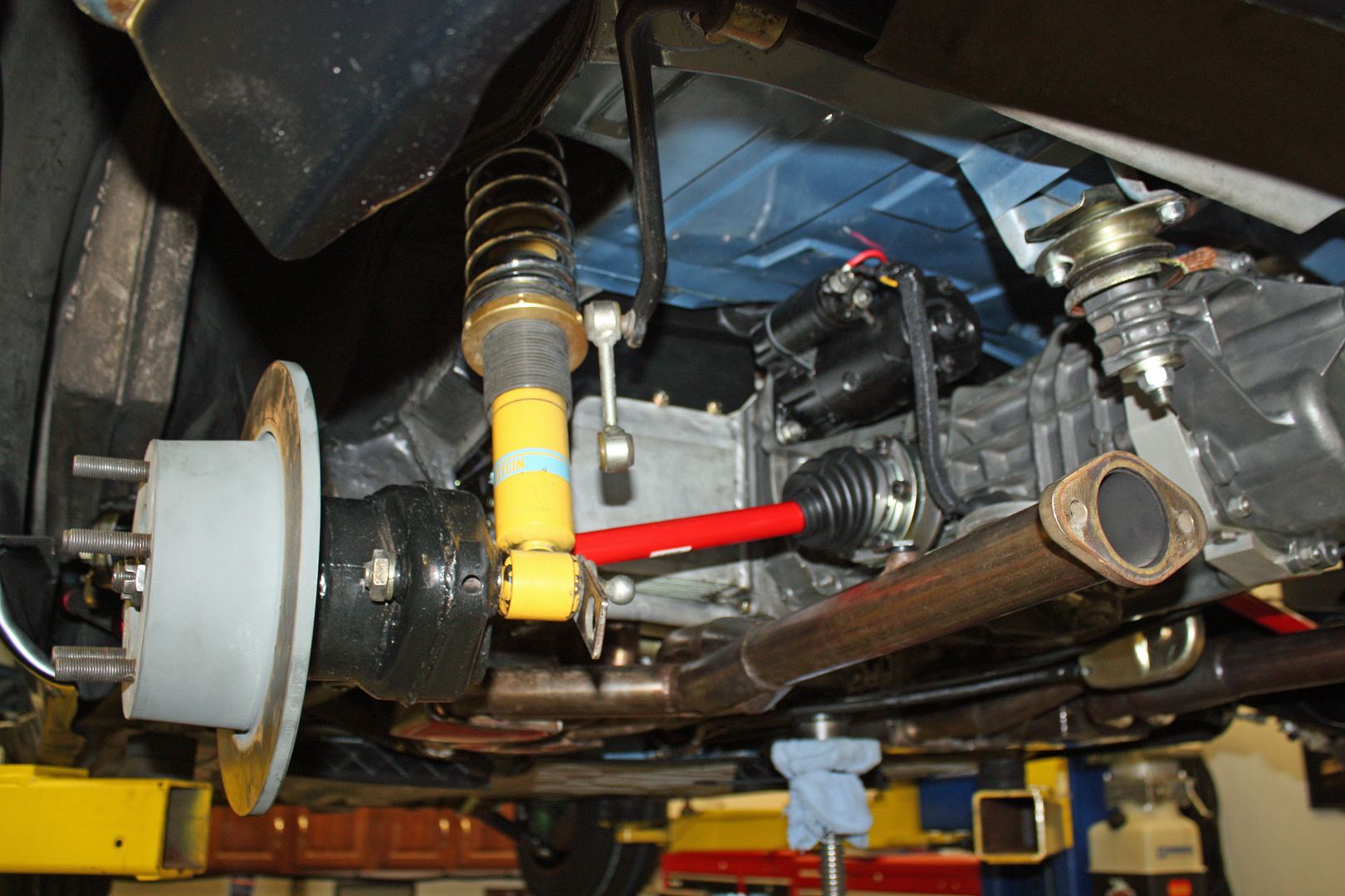
The end of yesterday saw me driving to The Driveshaft Shop to get twelve 45mm bolts to replace the 50mm bolts I was using. The 50mm bolts worked on the transmission flange as there was plenty of clearance on the rear of them. This morning I removed all of the gaskets. To give a bit more clearance on the rear of the flange, I broke out the die grinder and took a bit off the outer edge and at each threaded hole. I installed the outer flange and maneuvered the axle into place. To line up the holes, I used a small pick to find the hole. To raise the bottom of the CV a bit, I stuck a thin screwdriver between the flange and the trailing arm. Once I got that first bolt started, I used the pick to find the second hole opposite that first bolt. With that bolt started, it was a simple matter to start the rest of the bolts. I torqued the bolts to spec and torqued the axle nut and, voila, I was able to turn the hub. Success.
Now I could installed the CV on the transmission flange. I repeated this on the other side. This whole process took up my entire day. There were many trips and down my ladder to engage and dis-engage the parking brake. So I am a bit behind on getting the car ready to start but am relieved that I have a job completed that I knew was going to be an issue since everything here was modified. And, as anyone knows who works with CV joints, I spent a good bit of time cleaning up my counter, my tools and me!!

The day became more complicated once I began installing the axles. I had placed the axles in the trailing arms prior to installing the motor. I torqued the CV bolts and the main axle nut. Now I was ready to attach the CV's to the transmission flange. When I went to turn the hub to line up the CV bolt holes, it would not move. I checked to make sure the parking brake was off and it was. After considering things for a bit, I backed out the outer CV bolts and the hub would move. To test what bolt size would work, I placed some washers on the bolts to effectively make the bolts shorter. Even then, after trying different combinations of washers, I still was having an issue with everything locking up.
At this point I decided the axle had to come out of the trailing arm. There wasn't room to take the axle out with the CV joined to the flange so I separated them and pulled the axle out separately. With the axle out, I could see that there wasn't much clearance between the rear of the flange and the inside of the trailing arm and could see where the paint had been rubbed off when turning the flange with no axle attached. At this point I wasn't sure what to do. I wondered it I could shim the flange away from the inside of trailing arm.
To check on that, I called Chris Foley. He had never heard of someone having this issue before but, then again, he hadn't dealt with the axles and flanges that were being used here. He did not think it would be a good idea to shim the flange. He also reiterated his concern about using the CV gaskets. He said there were some applications that called for these gaskets but not with the CV's that I was using. I thanked him for his help and suggestions.
The end of yesterday saw me driving to The Driveshaft Shop to get twelve 45mm bolts to replace the 50mm bolts I was using. The 50mm bolts worked on the transmission flange as there was plenty of clearance on the rear of them. This morning I removed all of the gaskets. To give a bit more clearance on the rear of the flange, I broke out the die grinder and took a bit off the outer edge and at each threaded hole. I installed the outer flange and maneuvered the axle into place. To line up the holes, I used a small pick to find the hole. To raise the bottom of the CV a bit, I stuck a thin screwdriver between the flange and the trailing arm. Once I got that first bolt started, I used the pick to find the second hole opposite that first bolt. With that bolt started, it was a simple matter to start the rest of the bolts. I torqued the bolts to spec and torqued the axle nut and, voila, I was able to turn the hub. Success.
Now I could installed the CV on the transmission flange. I repeated this on the other side. This whole process took up my entire day. There were many trips and down my ladder to engage and dis-engage the parking brake. So I am a bit behind on getting the car ready to start but am relieved that I have a job completed that I knew was going to be an issue since everything here was modified. And, as anyone knows who works with CV joints, I spent a good bit of time cleaning up my counter, my tools and me!!


 12-03-2018, 08:05 PM
#119
Racer
Thread Starter
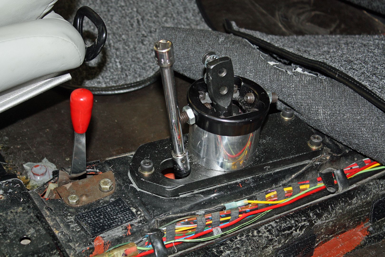
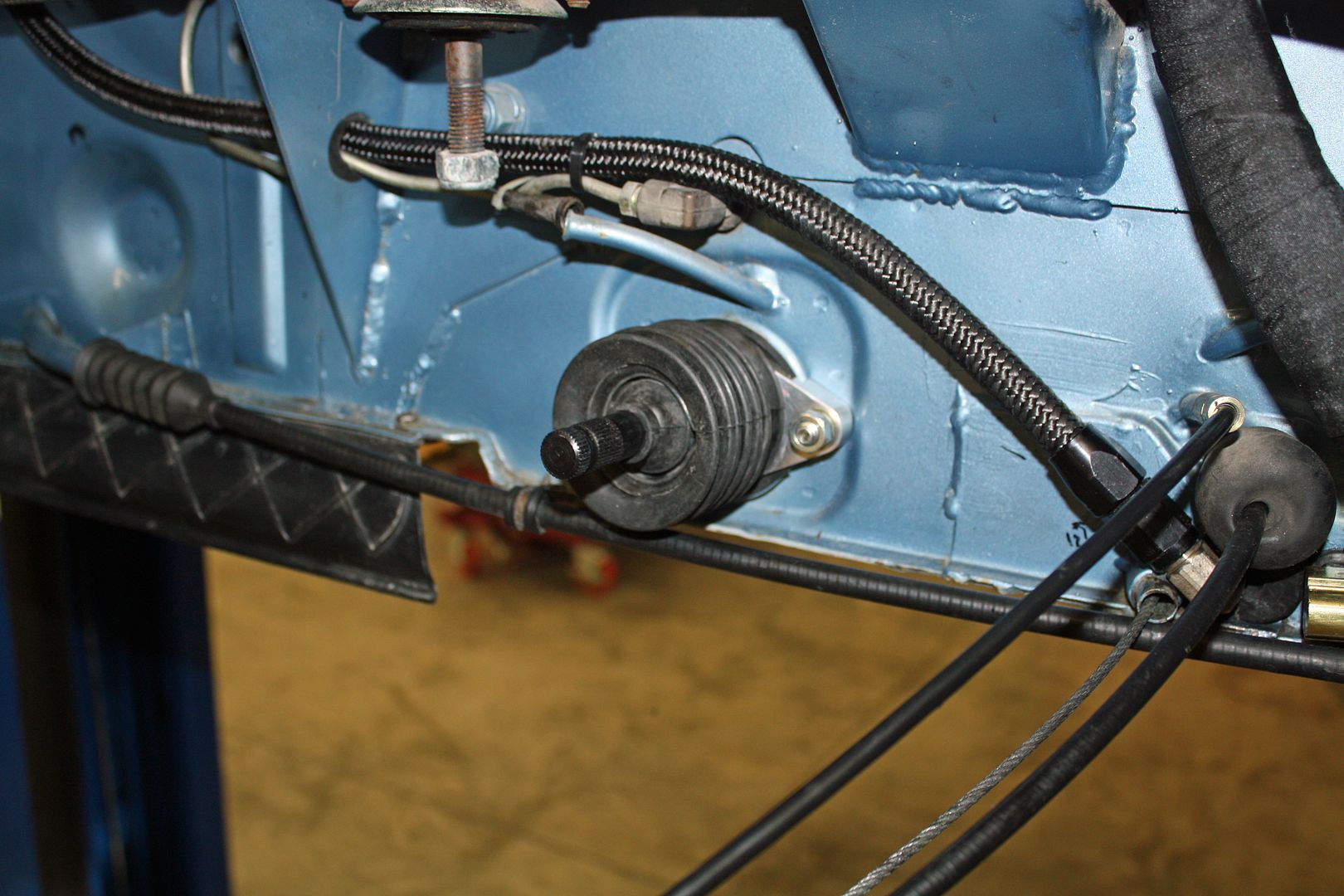
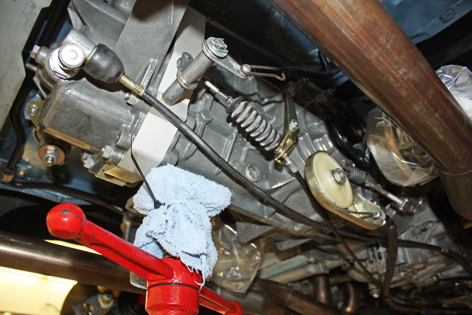
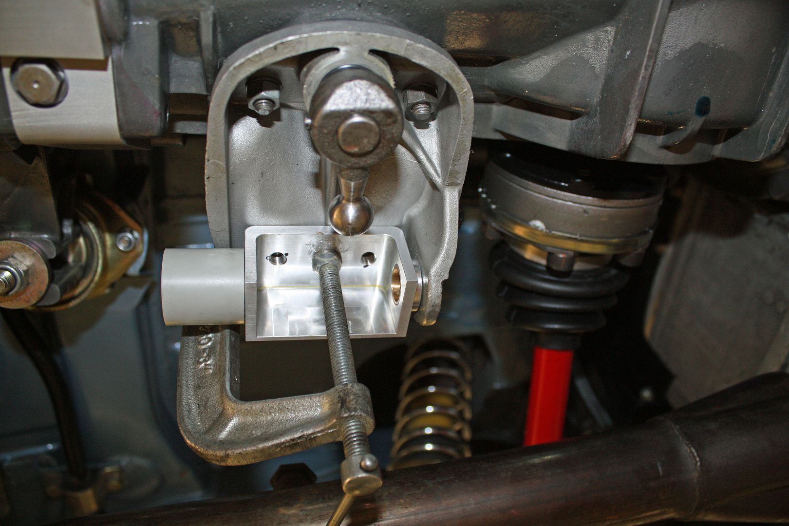
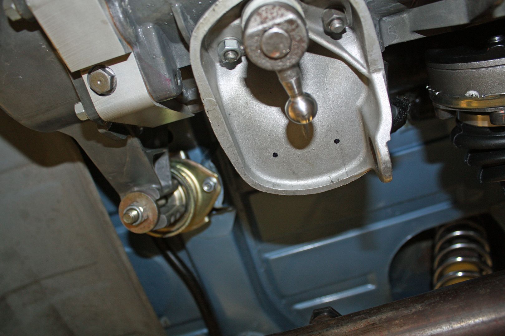
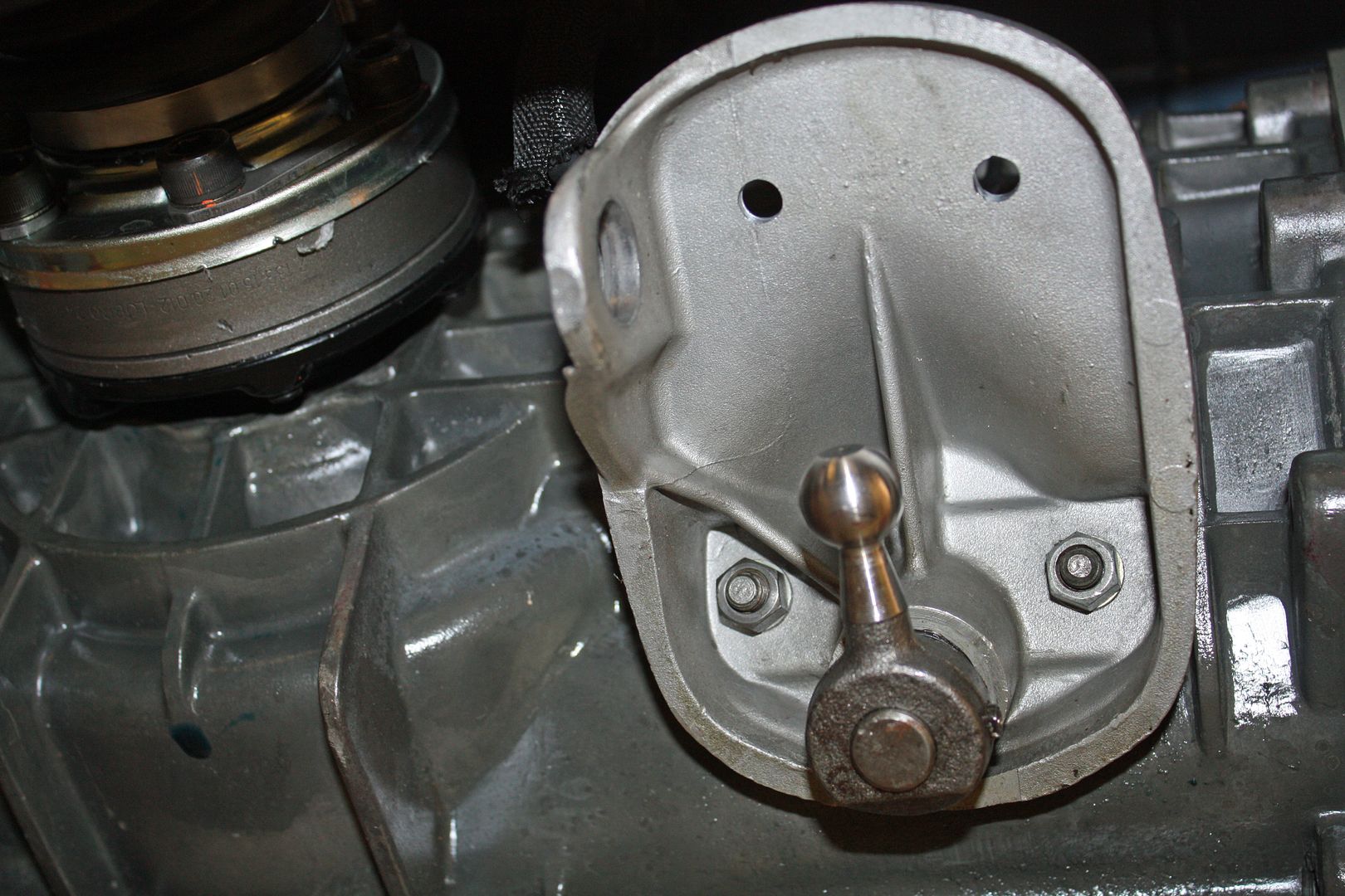
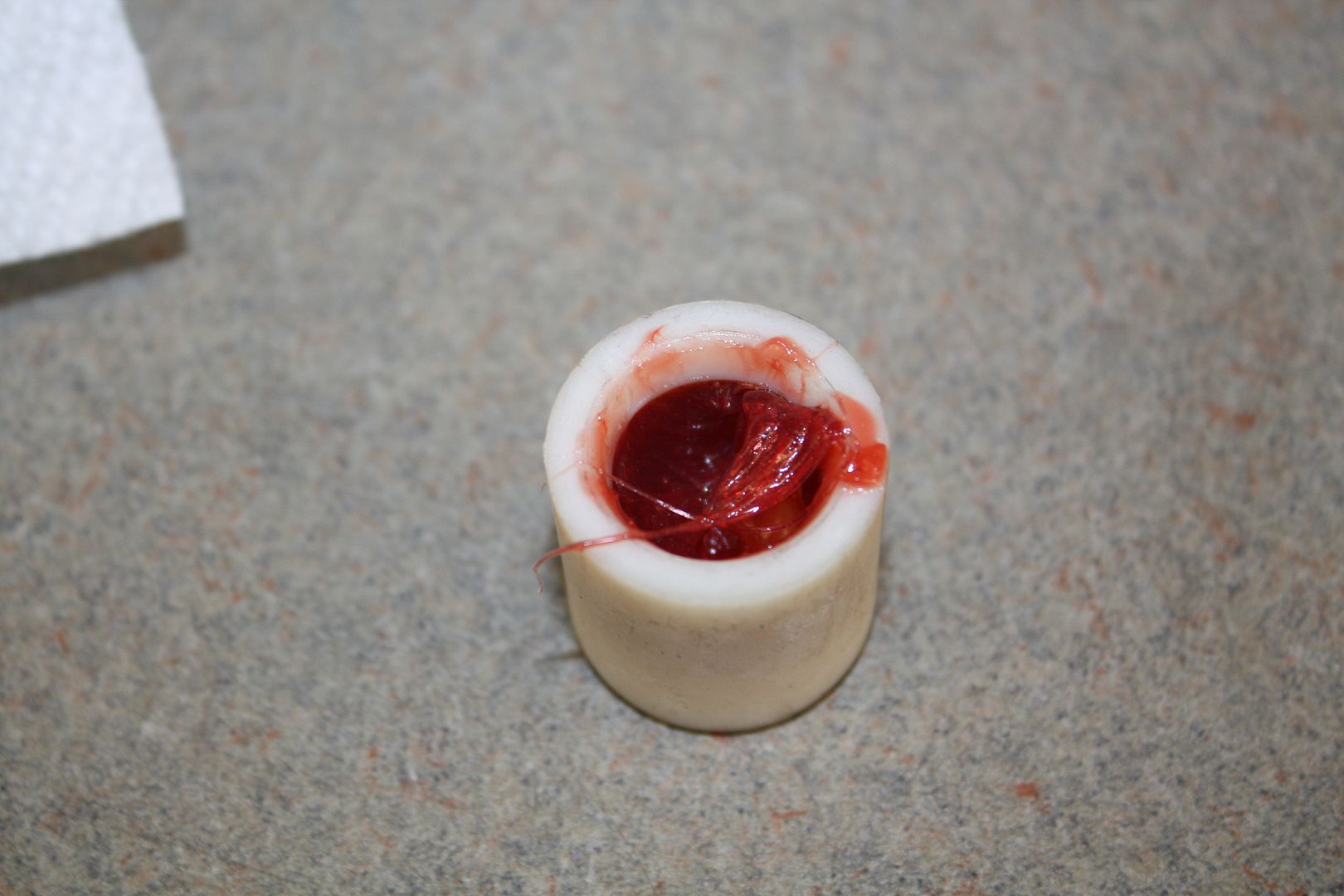
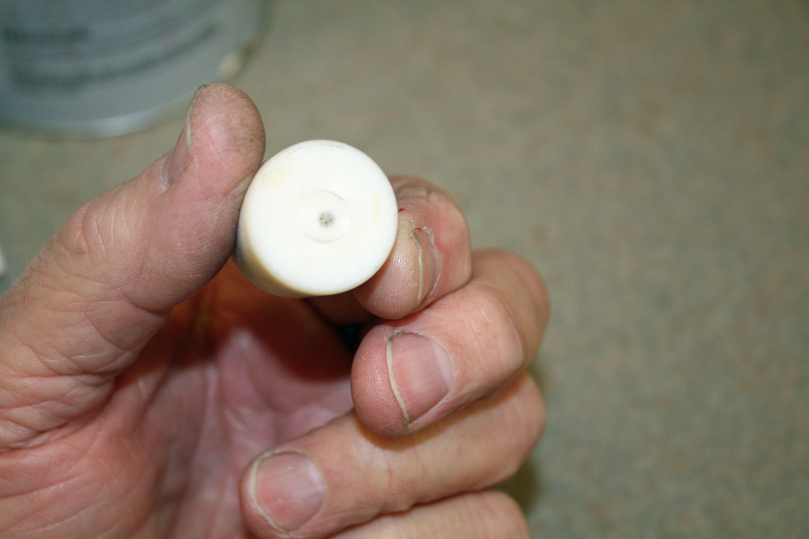
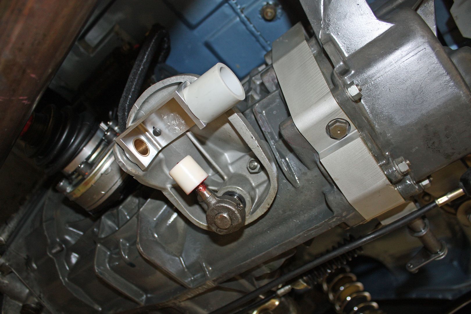
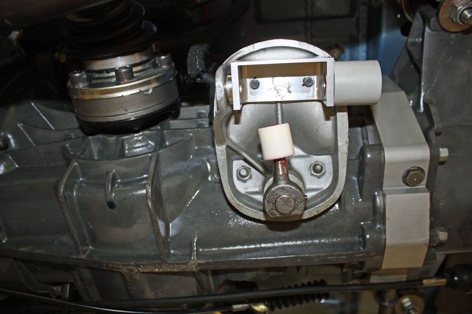
Today I worked mainly on the Jwest side shift linkage at the transmission. After removing the stock plastic bushing from the shift console, I clamped the linkage support to the shift console. I marked the two holes and drilled them. Next up was installing the new ball cup bushing after applying lots of grease. I drilled a small hole in that bushing which makes it easier to install. With that in place, I then could mount the linkage support.


 12-03-2018, 10:27 PM
#120
Racer
Thread Starter
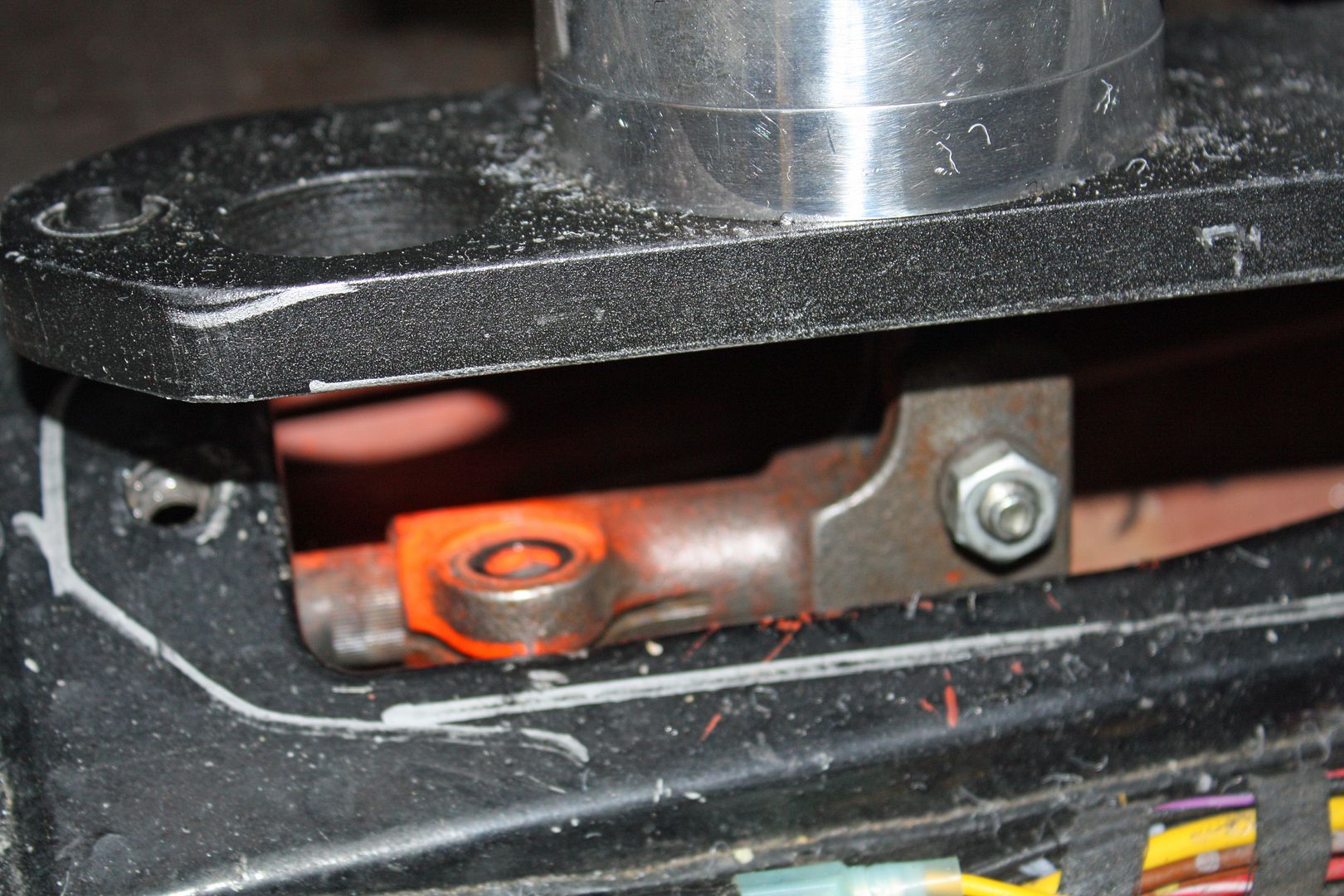
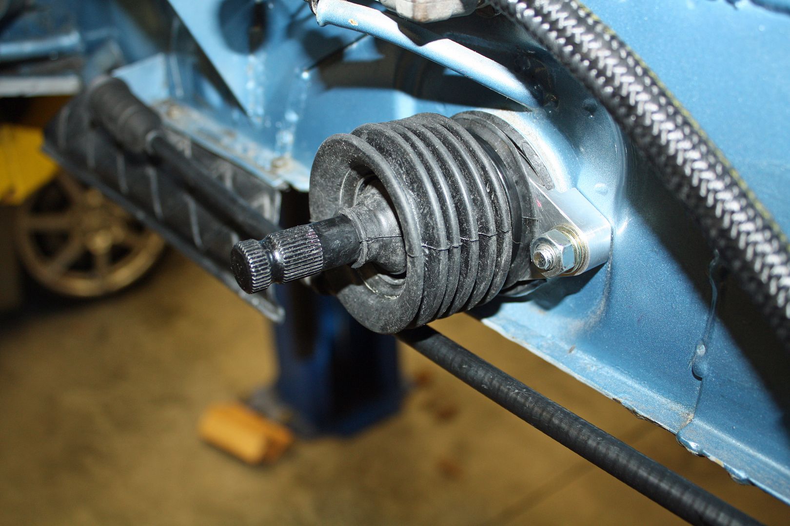
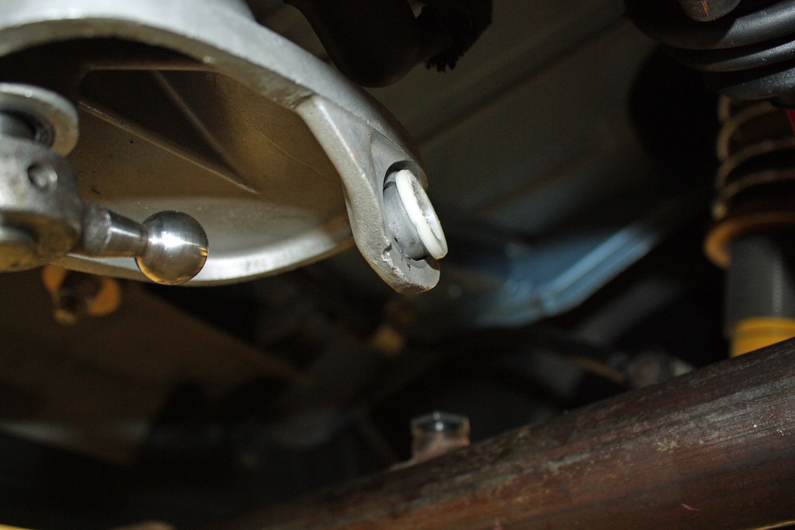
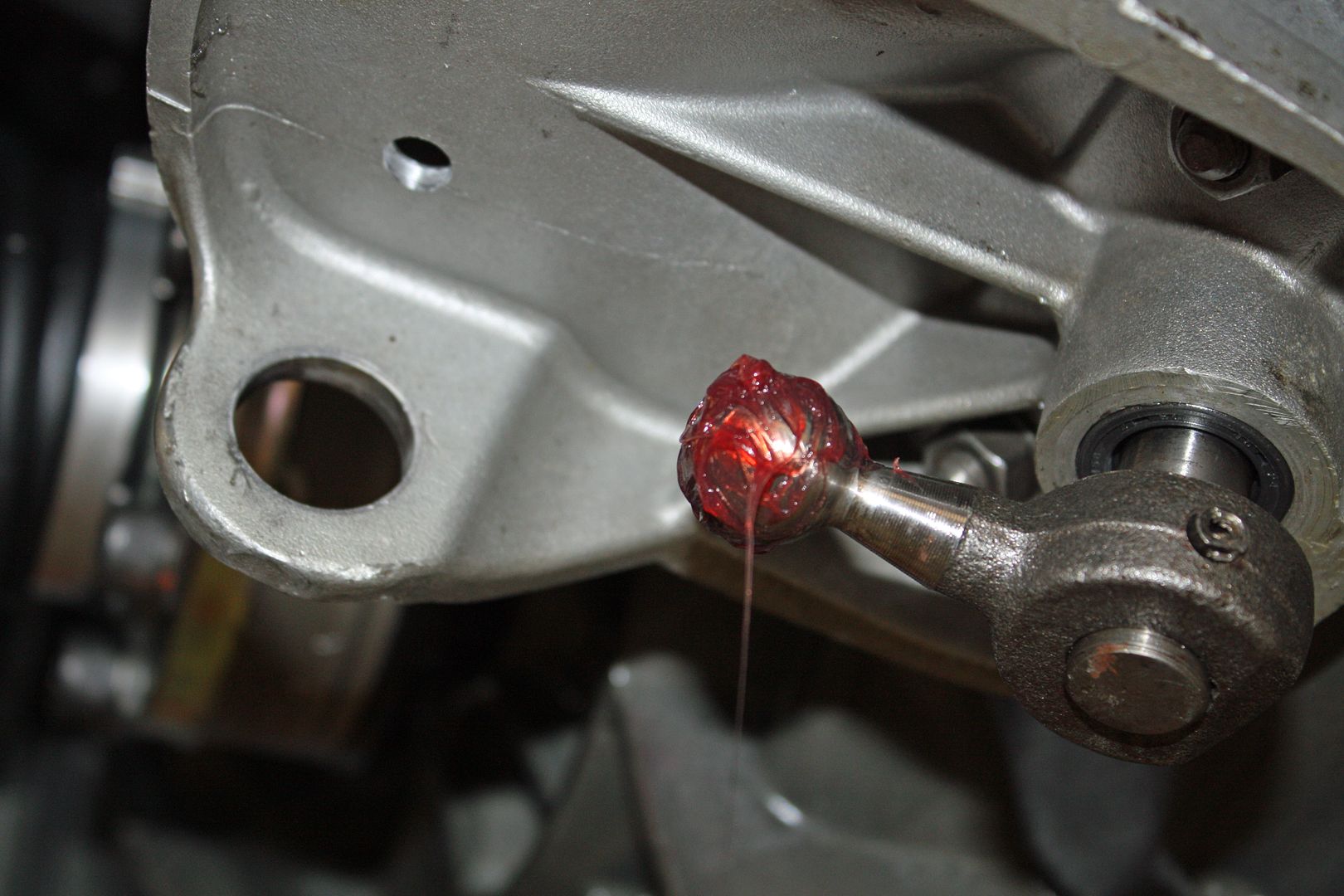
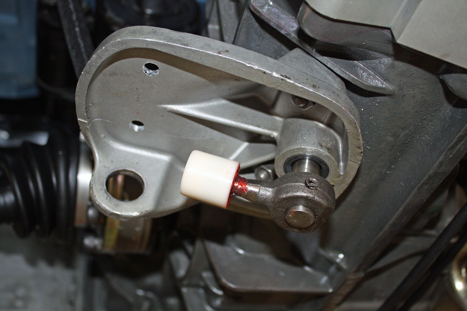
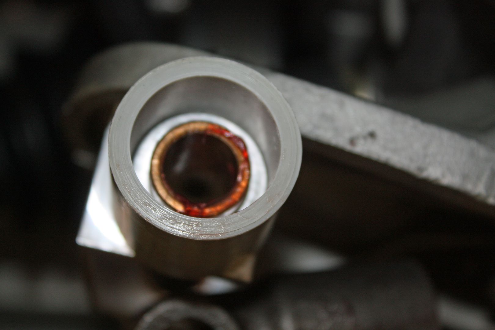
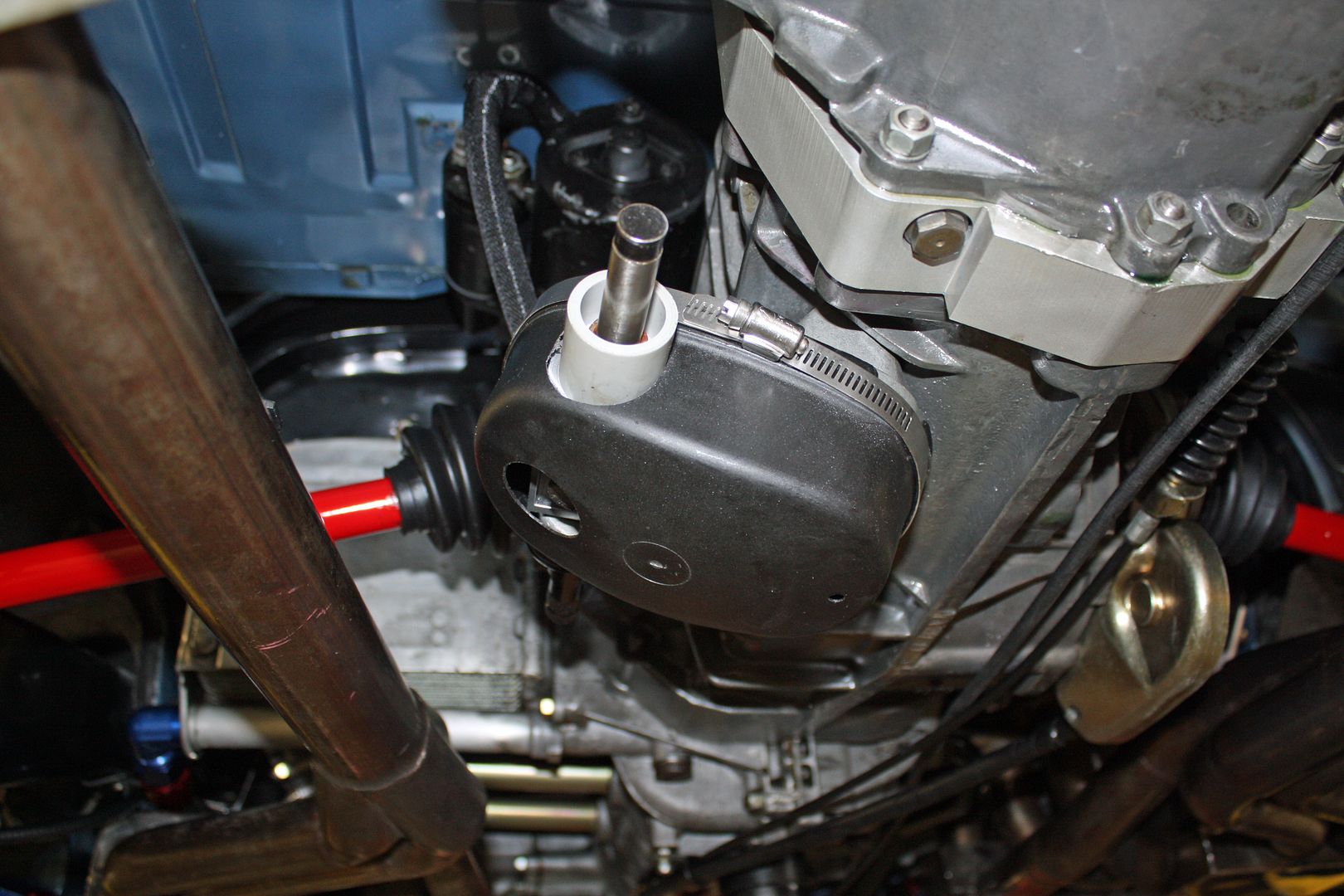
The next step was to install the rod through the shift cup as a test to make sure everything fit and to check for clearance issues.
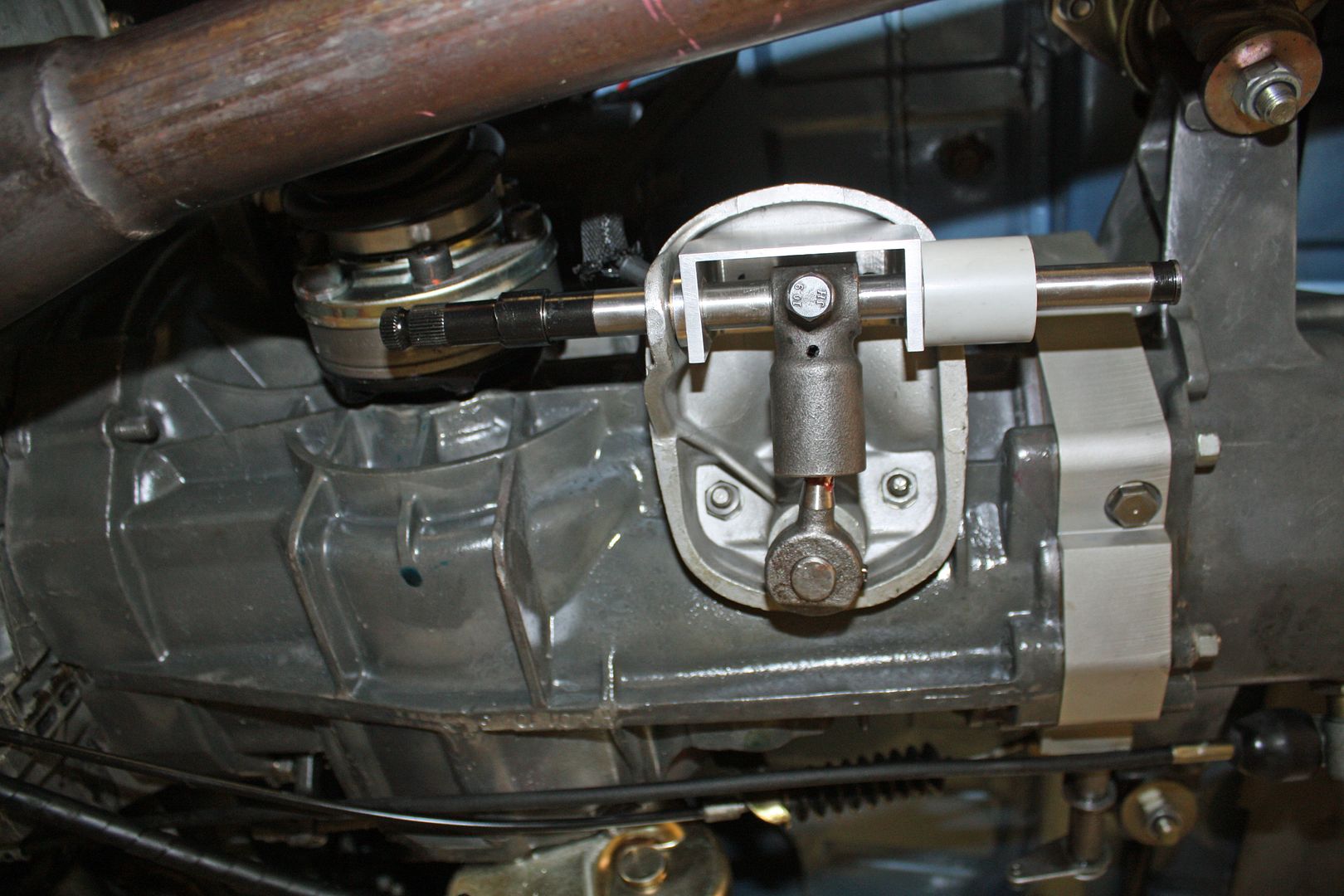
The rod had to be removed so the console cap could be installed. Once the cap was on, I could insert the shift rod through the shift cup and out the rear of the shift console after lubricating the bushings. There is a flat spot on the shift rod where an M8 bolt is used to secure the shift cup to the rod. Once all that is in place, the boots can be installed on both ends of the shift rod.

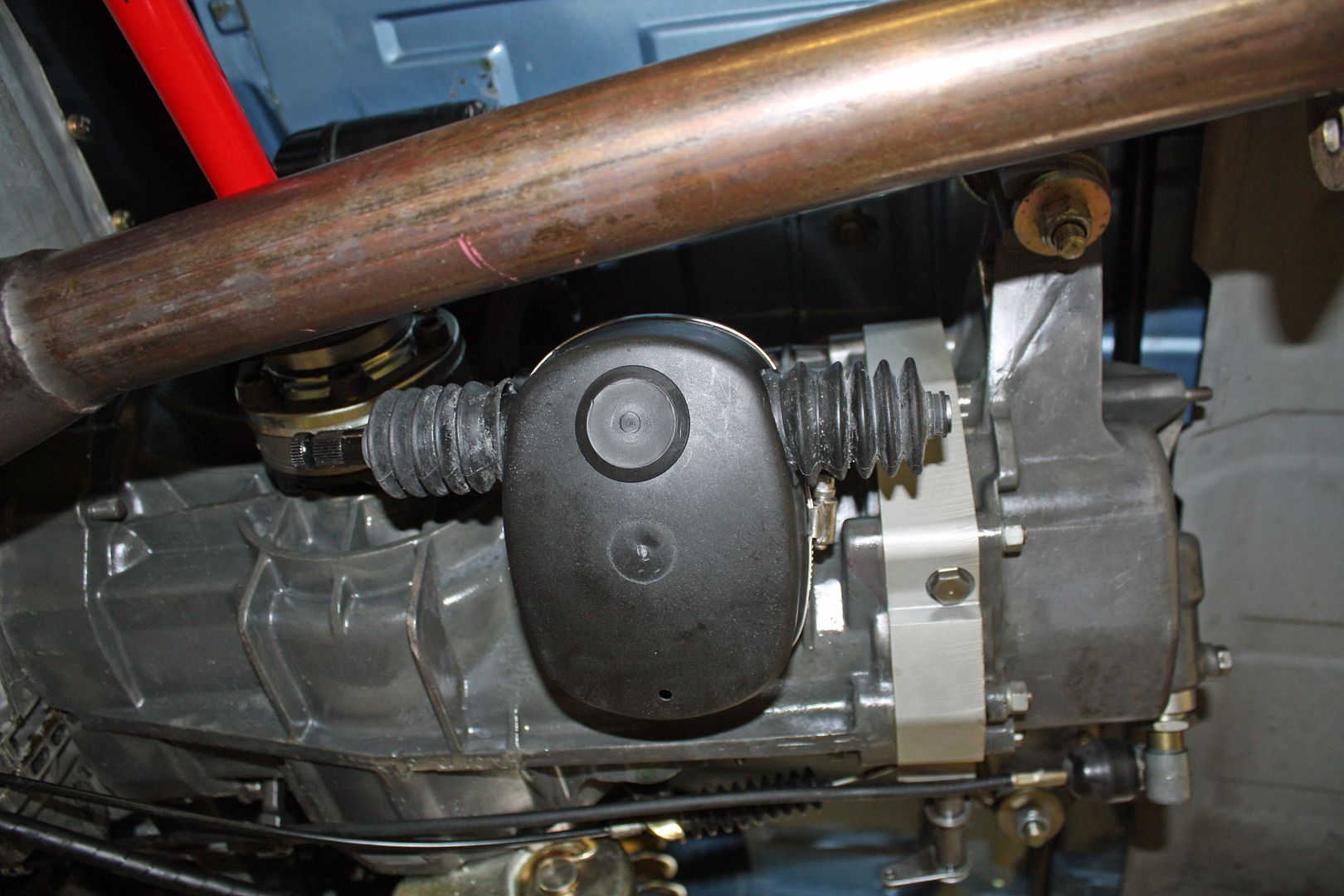
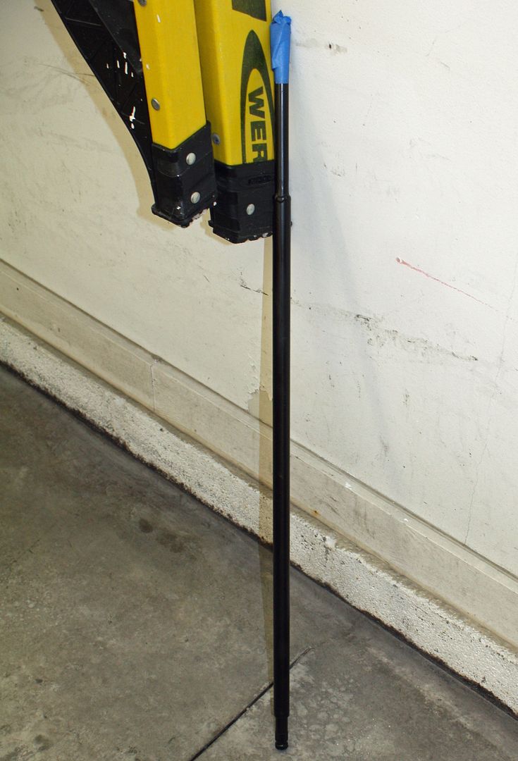
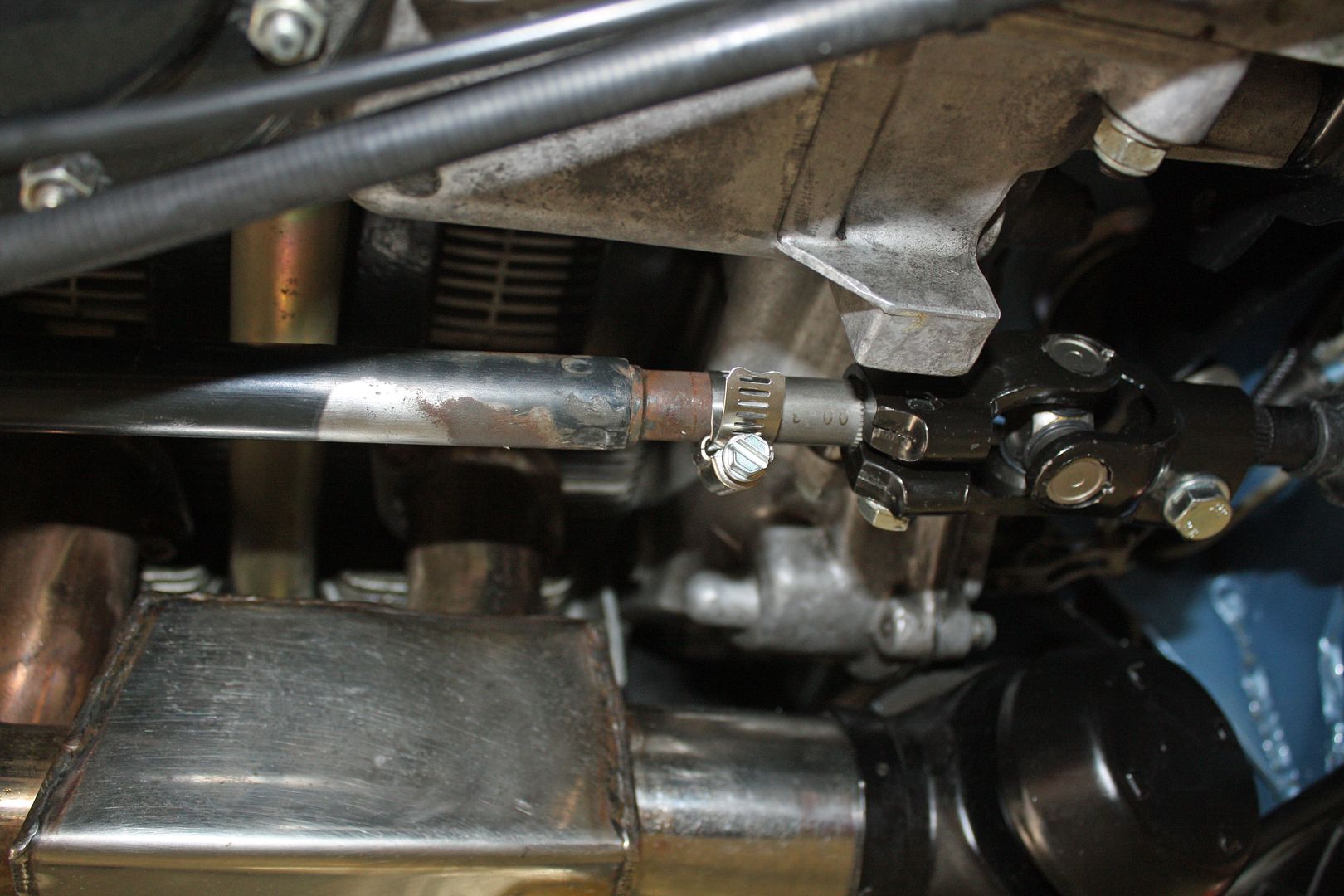
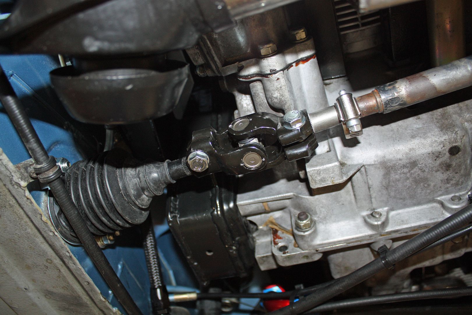
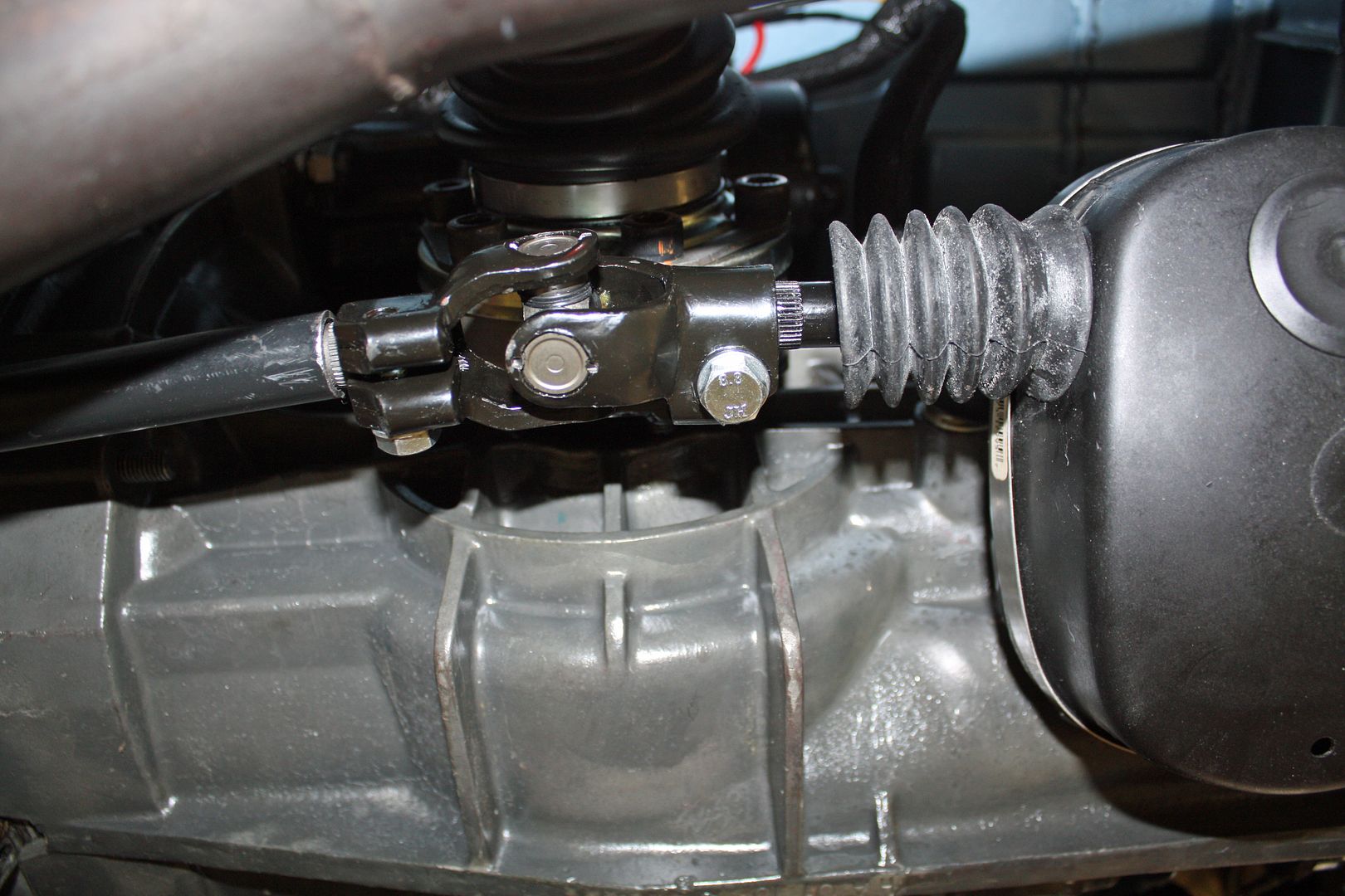
After installing the u-joints and the stub shafts on the shift rod and the front shift rod, a new center shift tube must be made. The stock center shift tubes are way to long for this application and there is no need for a kink in them. After pondering what I was going to use to make this rod, I thought of the stock front shift rod that we had cut one end off of. I dug it out and it was the close to being the correct length. At the rear, this rod slid over the stub shaft. At the front, the two stubs would need to be butt welded.
I called my son and he came over after work. To show him how I thought everything would work, I used a hose clamp to fasten the front stubs together. He thought my idea would work. We measured how long this rod would be once it is welded to both shift stubs. Once we had the measurement, we removed the shift stubs and he took everything with him to make the center shift tube.

The rod had to be removed so the console cap could be installed. Once the cap was on, I could insert the shift rod through the shift cup and out the rear of the shift console after lubricating the bushings. There is a flat spot on the shift rod where an M8 bolt is used to secure the shift cup to the rod. Once all that is in place, the boots can be installed on both ends of the shift rod.


After installing the u-joints and the stub shafts on the shift rod and the front shift rod, a new center shift tube must be made. The stock center shift tubes are way to long for this application and there is no need for a kink in them. After pondering what I was going to use to make this rod, I thought of the stock front shift rod that we had cut one end off of. I dug it out and it was the close to being the correct length. At the rear, this rod slid over the stub shaft. At the front, the two stubs would need to be butt welded.
I called my son and he came over after work. To show him how I thought everything would work, I used a hose clamp to fasten the front stubs together. He thought my idea would work. We measured how long this rod would be once it is welded to both shift stubs. Once we had the measurement, we removed the shift stubs and he took everything with him to make the center shift tube.


