
Projects on my new, to me, 1974 914-6
 08-31-2018, 08:58 PM
#31
Racer
Thread Starter

On the other hand, there is a lot of black trim on the rockers and the valances. One of the extra set of 15" wheels that I have does have black centers. They looked good on the car.
BTW, I have a set of 15x7 and 15x8 replica's with polished lips and polished raised areas on the spokes. I also have six 15" wheels with black centers. Two are 15x7's and four are 15x9's. At some point I will be selling all of these.
 08-31-2018, 10:48 PM
#32
Racer
Thread Starter
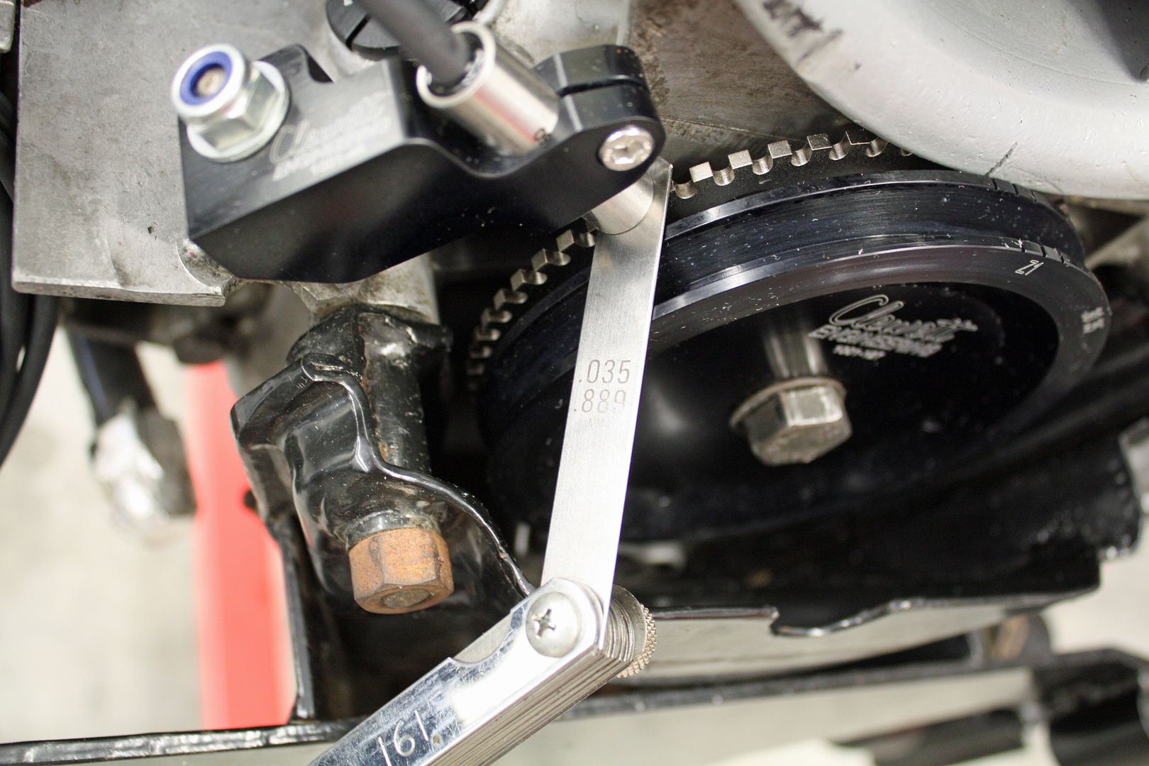
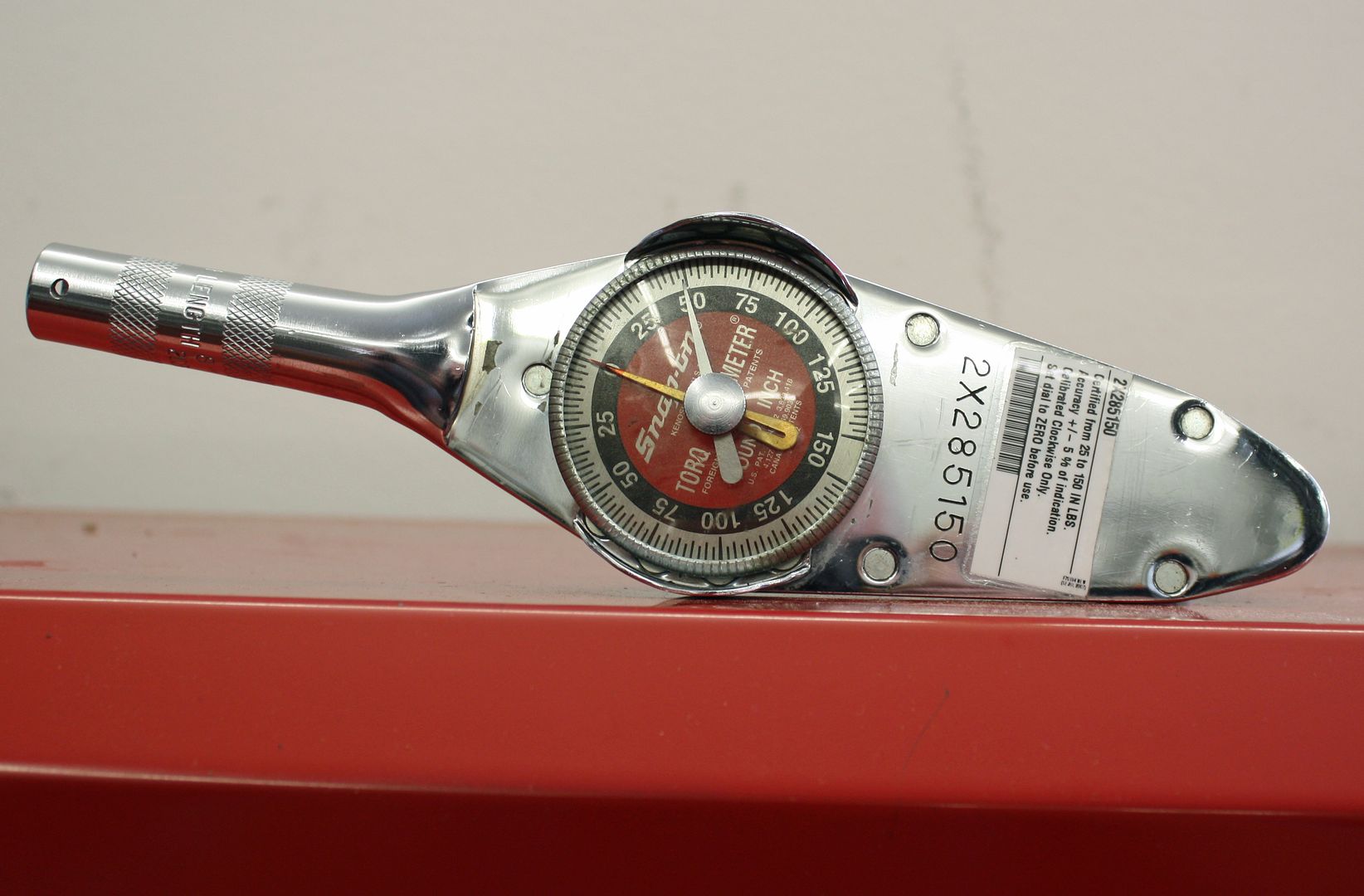
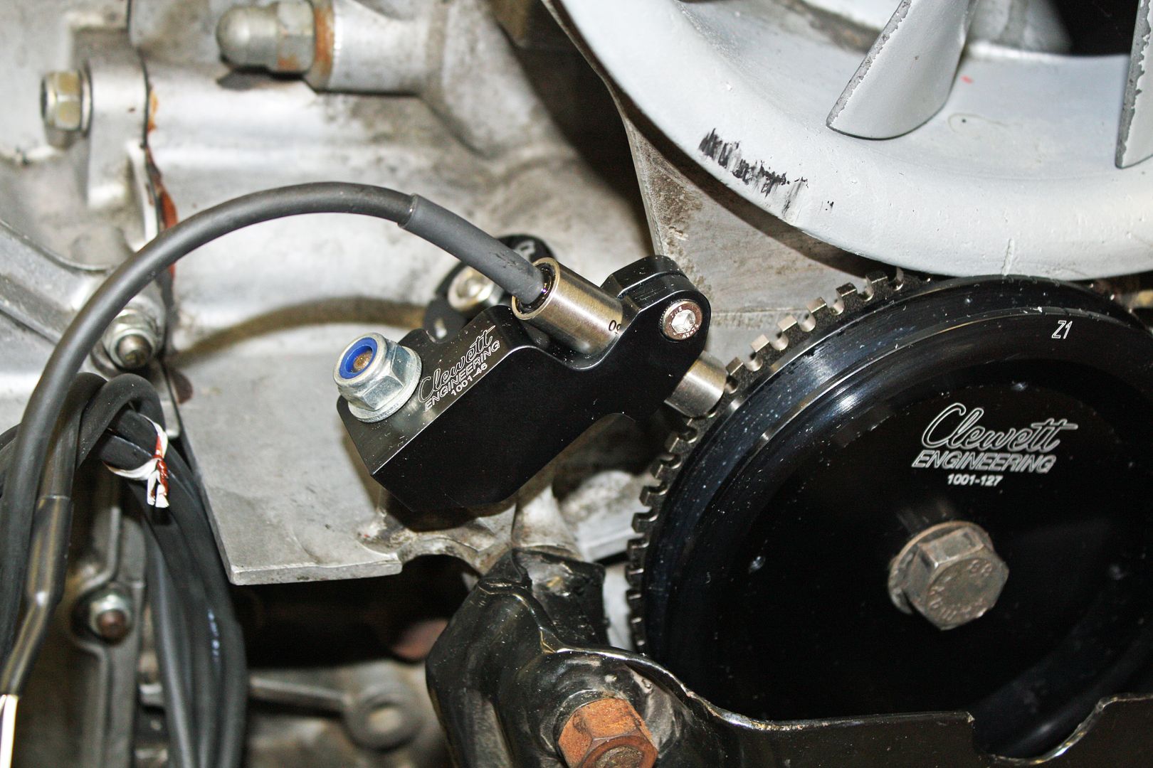
I worked all afternoon and accomplished quite a bit. First off I installed the crank position sensor in the holder. It called for a .035 gap. The tightening bolt called for 45 in/lb.
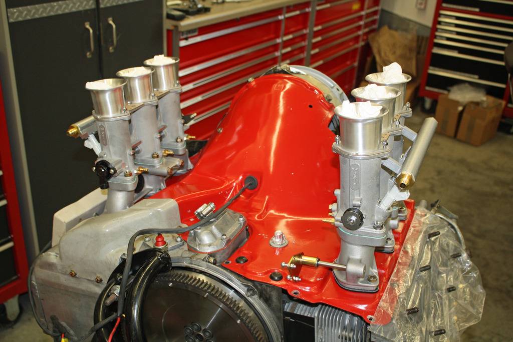
Time to work on the intake manifolds. The studs need to be installed as well as the bell crank. Next up was prepping the motor to accept the manifolds. An insulator is sandwiched between two gaskets for each cylinder.
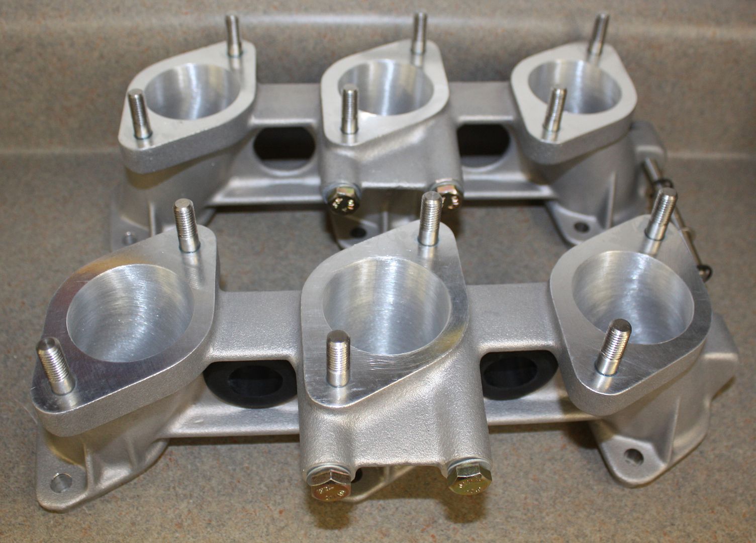
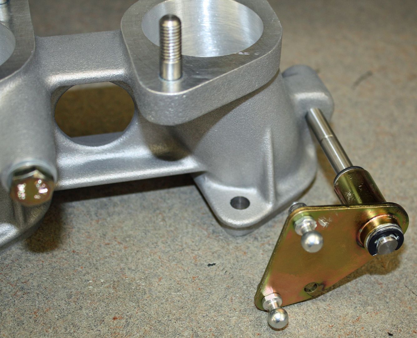
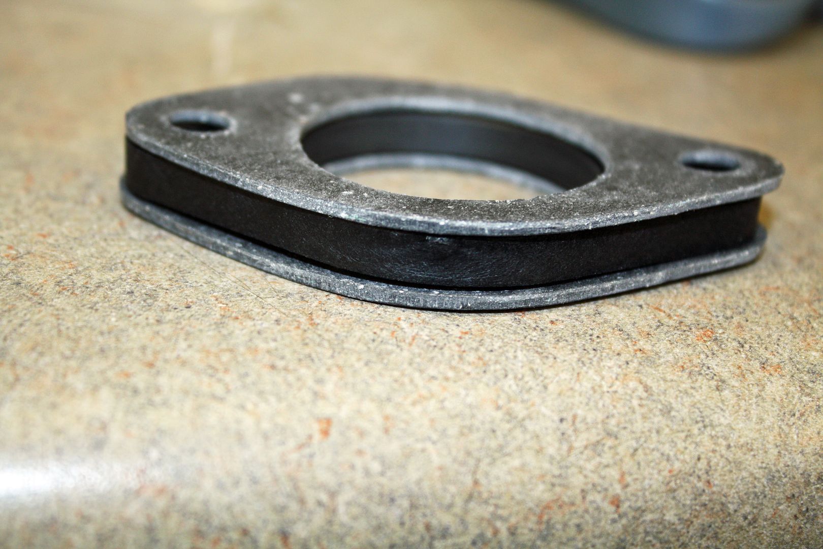
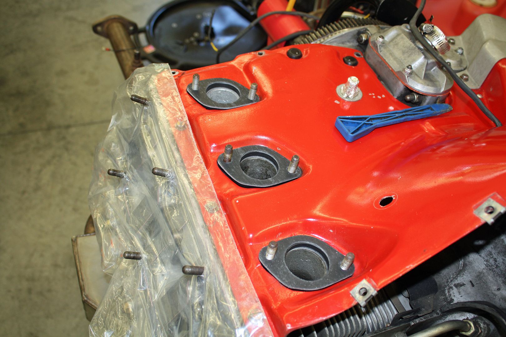


Time to work on the intake manifolds. The studs need to be installed as well as the bell crank. Next up was prepping the motor to accept the manifolds. An insulator is sandwiched between two gaskets for each cylinder.


 08-31-2018, 11:01 PM
#33
Racer
Thread Starter
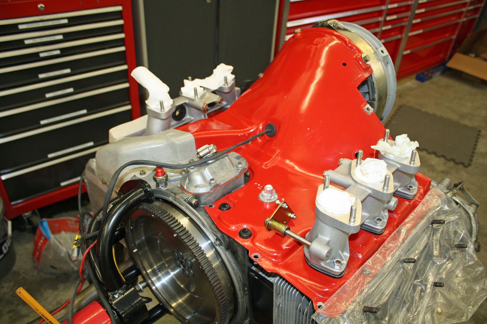
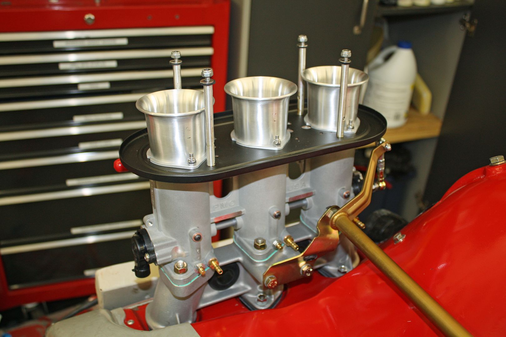
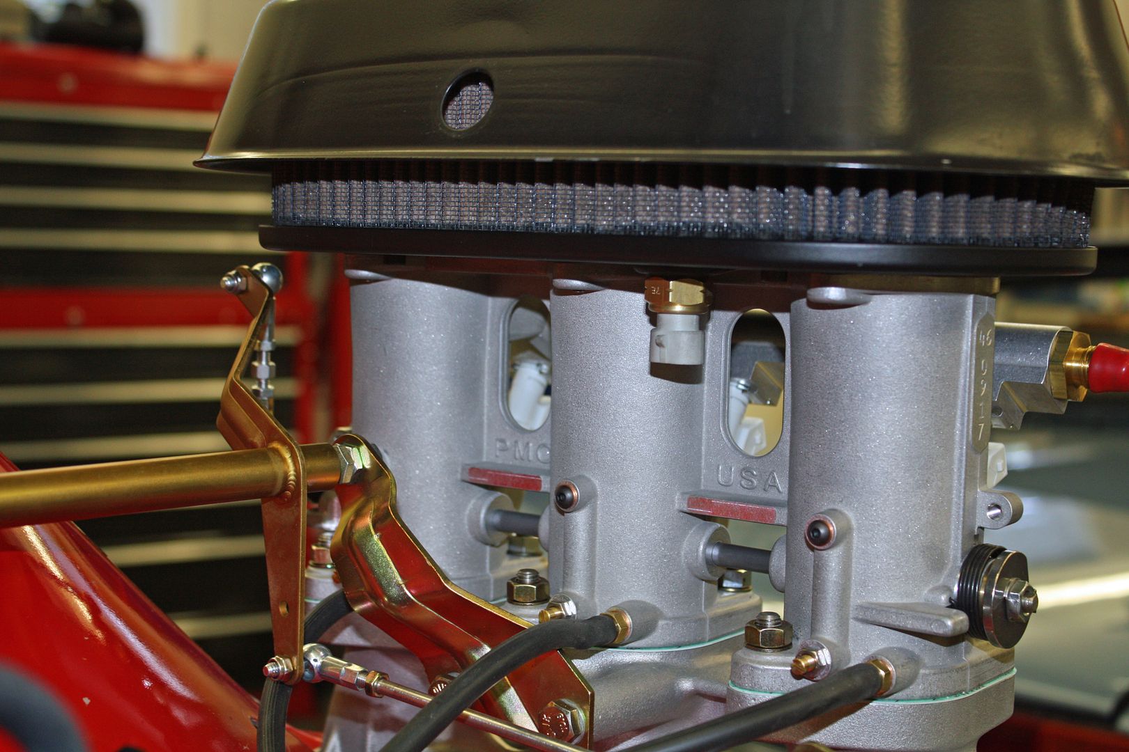
Now it was the throttle bodies turn. First up is installing a retaining clip on each fuel injector base. After oiling the "O" ring, i inserted the injector into the fuel rail. Once it is fully seated, the retaining clip is rotated to lock it in place.
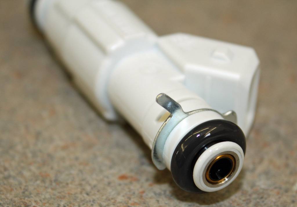
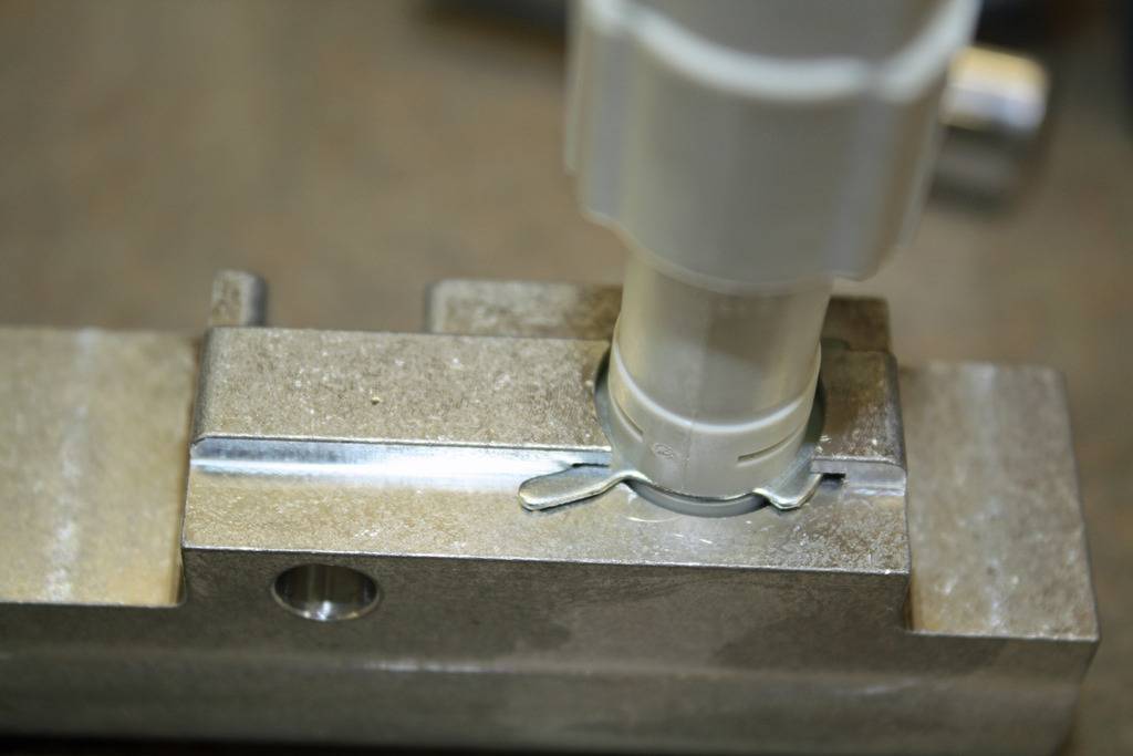
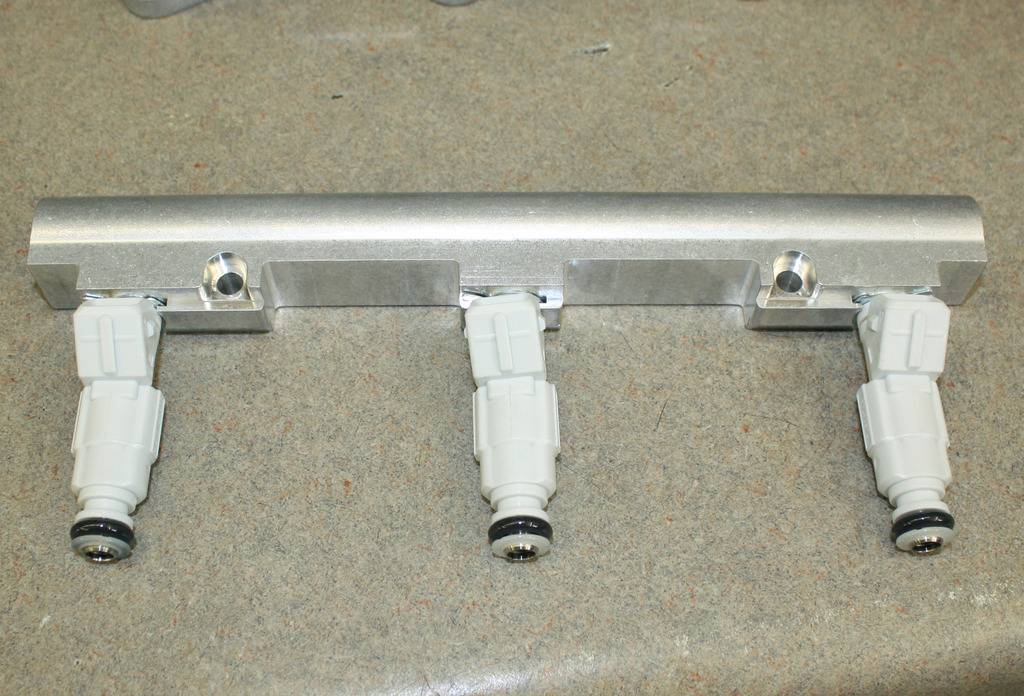
Once the injectors are secured to the fuel rail, the other end of the injectors is inserted into the throttle body. The fuel rail is secured to the throttle body with a bolt going through a spacer.
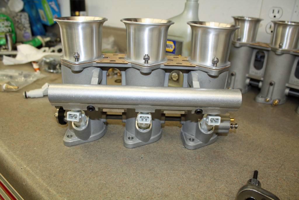
Next the AN fittings with "O" rings are fitted to each end of the fuel rails.
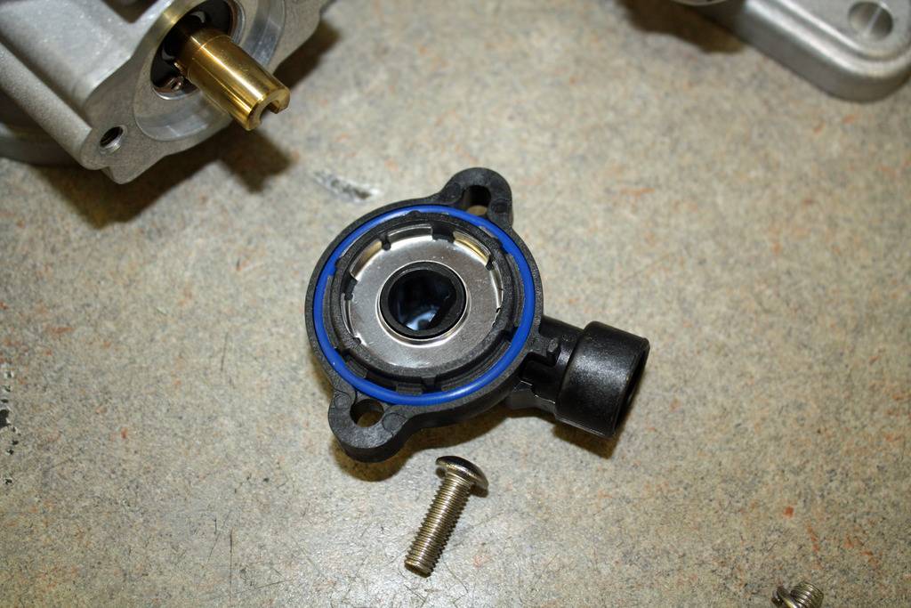
The Throttle Position Sensor (TPS) in fitted to one end of the throttle shaft.
Now each throttle body can be fitted to the intake manifolds.


Once the injectors are secured to the fuel rail, the other end of the injectors is inserted into the throttle body. The fuel rail is secured to the throttle body with a bolt going through a spacer.


Next the AN fittings with "O" rings are fitted to each end of the fuel rails.

The Throttle Position Sensor (TPS) in fitted to one end of the throttle shaft.


Now each throttle body can be fitted to the intake manifolds.
 09-01-2018, 10:51 PM
#35
Racer
Thread Starter
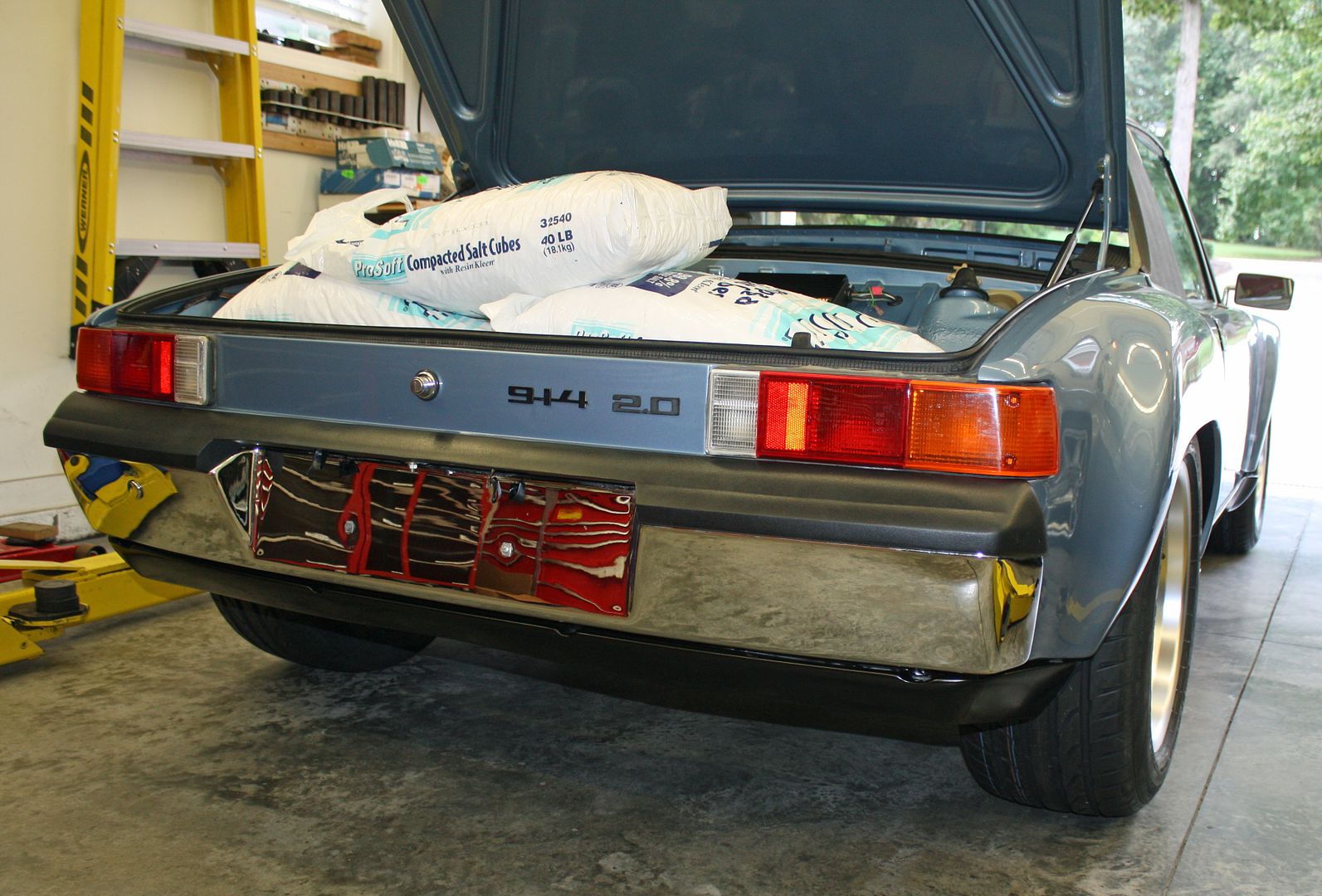
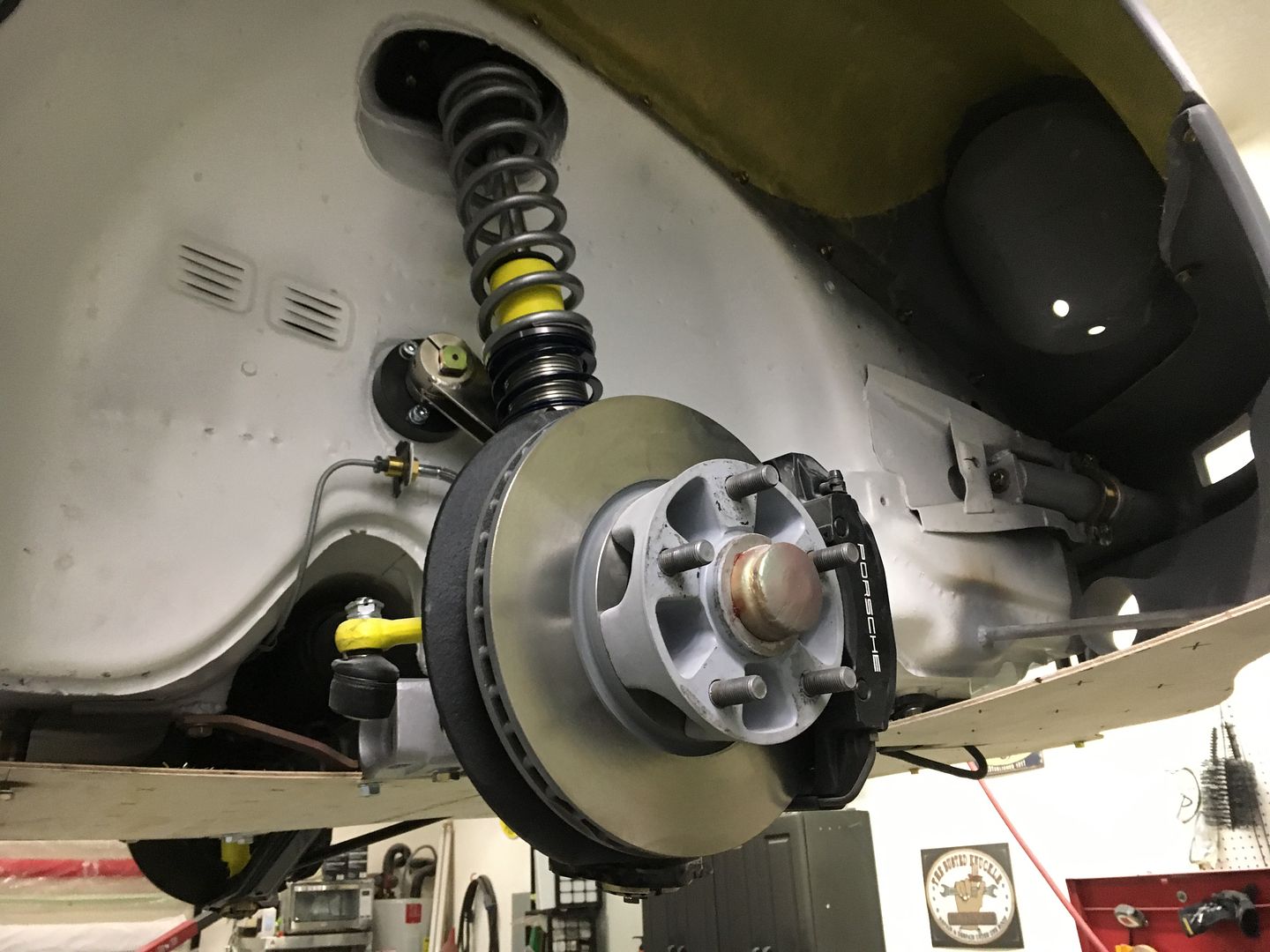
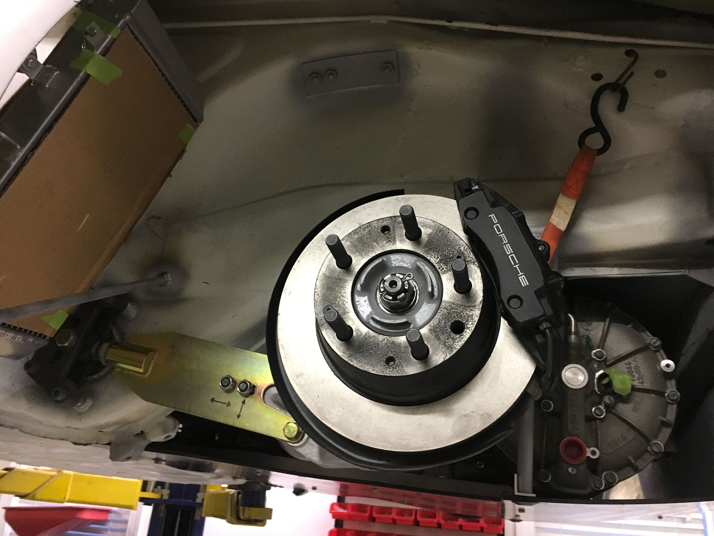
Spent most of the morning getting the tires mounted. Tech said they balanced well. I had to use a 1/4" spacer on the rears to clear the inner fender. To simulate the drivetrain, I loaded 200lbs of salt in the very rear of the trunk. The car was only lowered about a 1/4" with all of that weight. Stiff suspension!! Lowering it reduced the rear wheel clearance. Since I have room on the outside, I will be using a larger spacer. Once I have the clearances where I want them to be, I can install the correct size wheel studs.
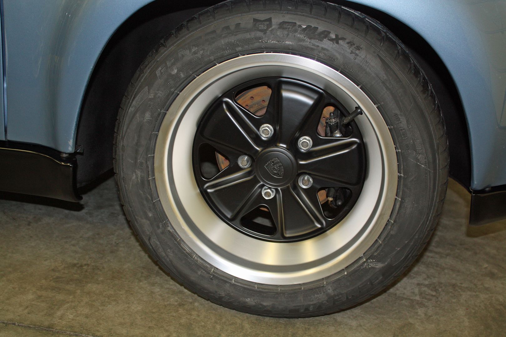
To complete the Chinese wheel configuration, I installed the center caps I had purchased earlier this summer on eBay. They cost $118 for a set of four with free shipping from China. They are of surprisingly good quality. I should have taken a photo of the rear as they are anodized like the factory caps. And they fit perfectly.
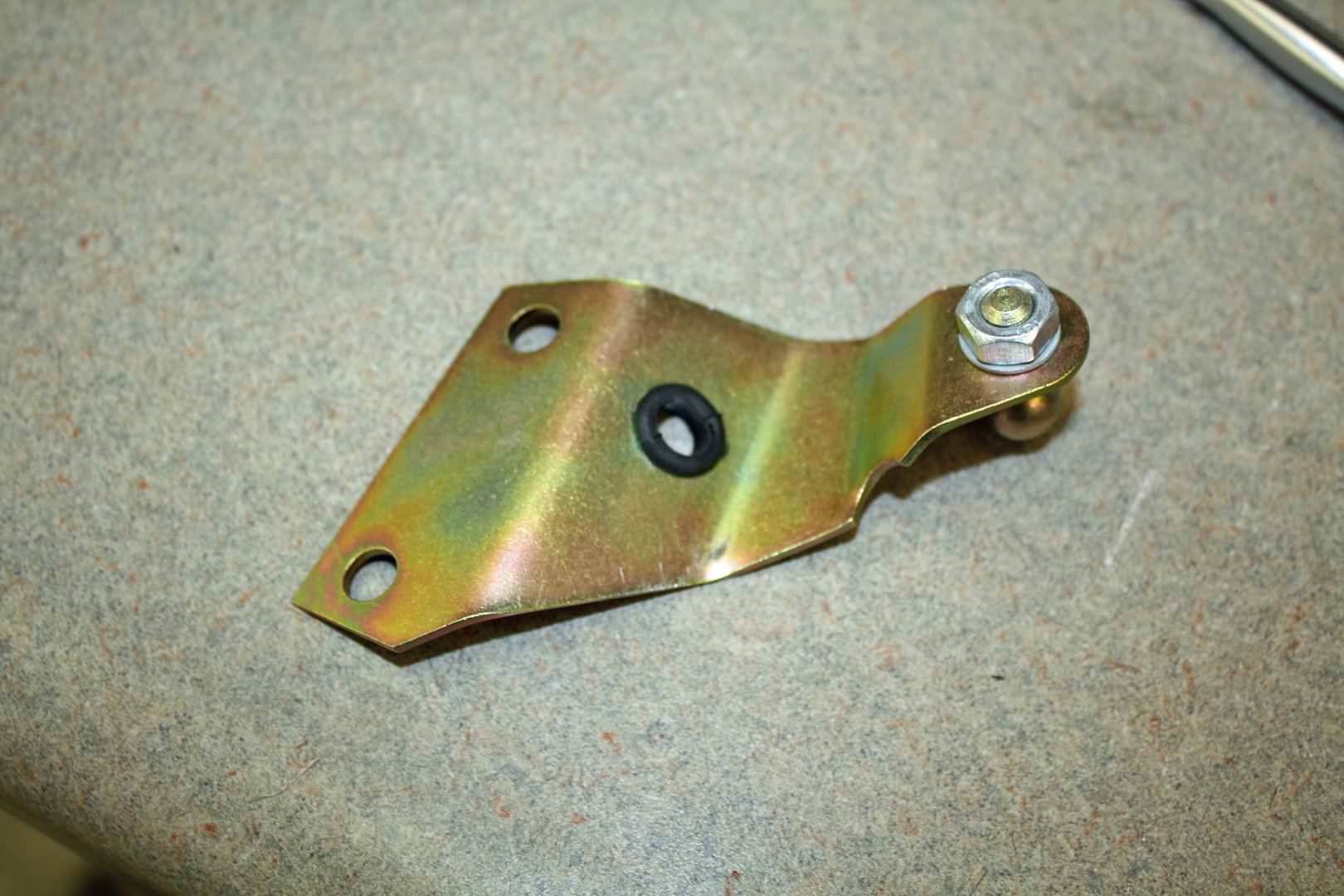
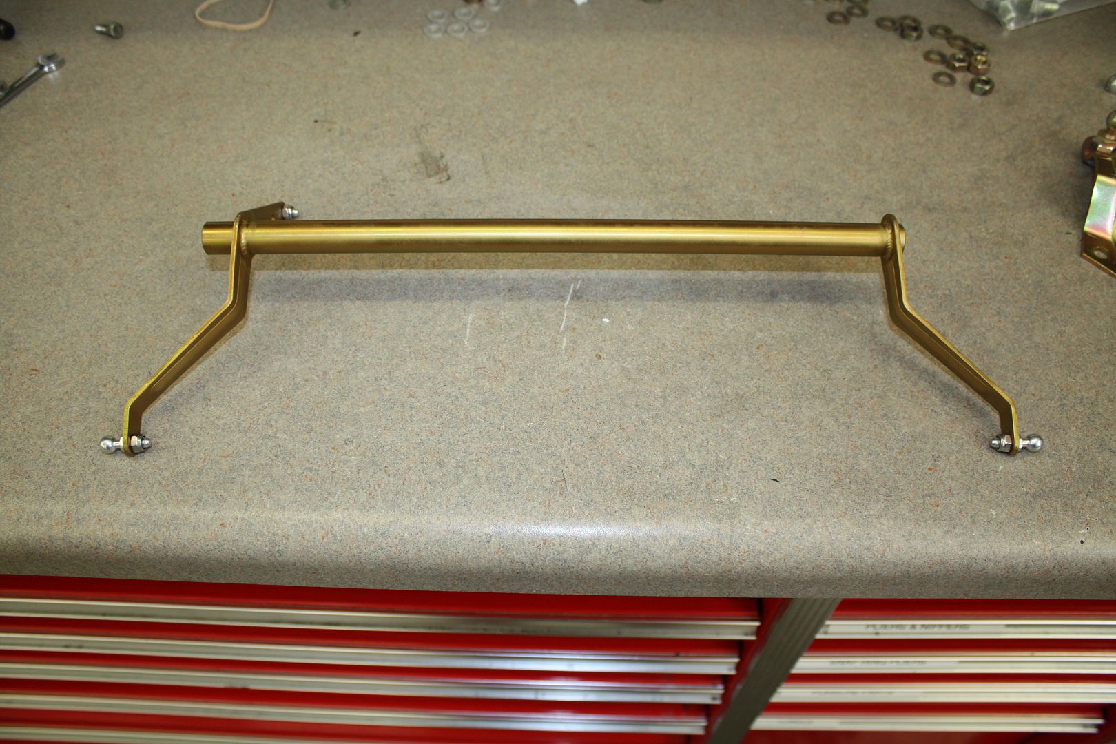
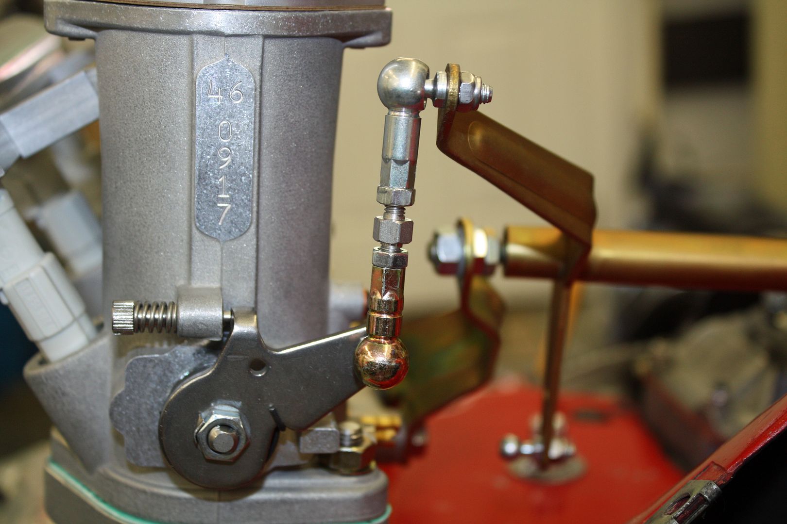
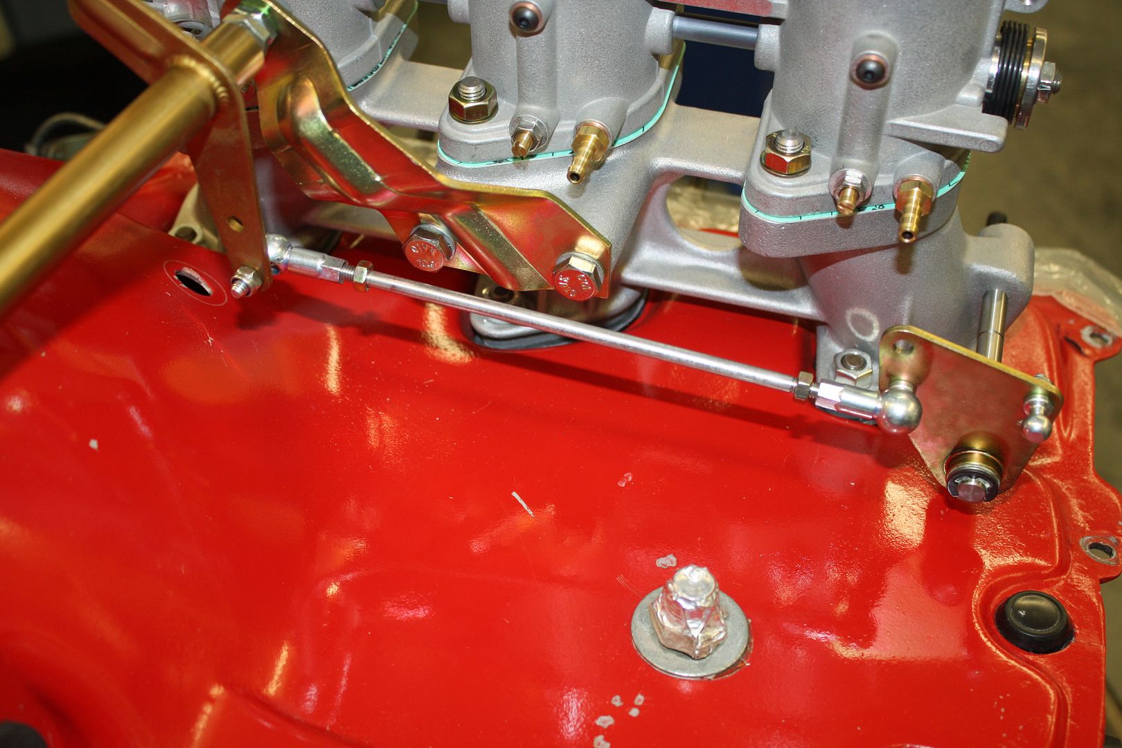
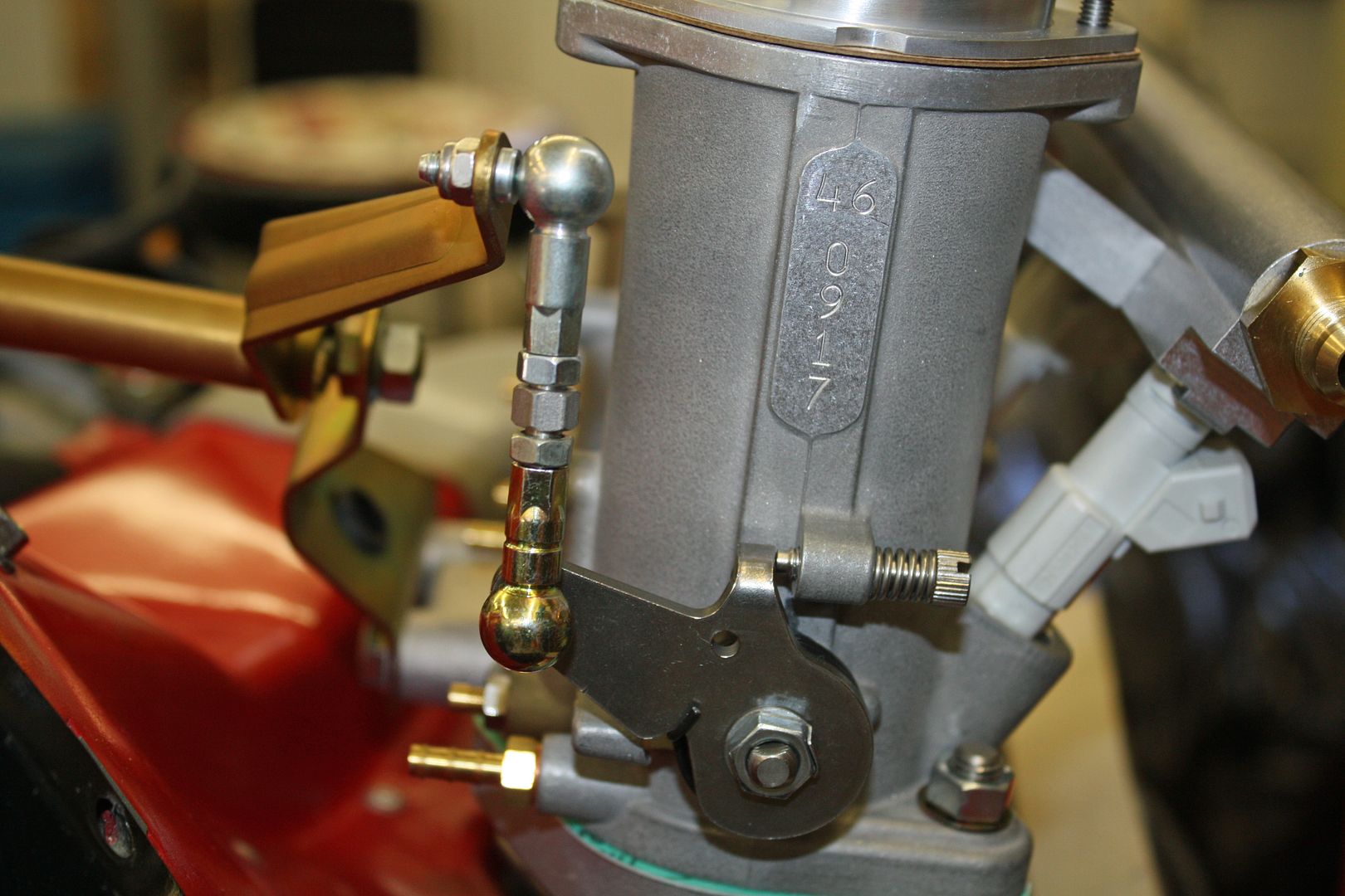
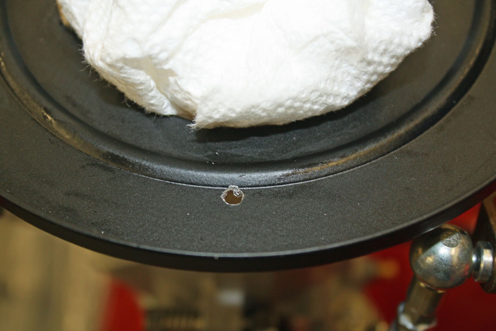
I did get to spend a little time on the linkage. Richard's instructions recommend drilling a half inch hole in the right side mount for routing a vacuum hose to the port behind the mount. I also had to install the rod ends on the cross bar.


To complete the Chinese wheel configuration, I installed the center caps I had purchased earlier this summer on eBay. They cost $118 for a set of four with free shipping from China. They are of surprisingly good quality. I should have taken a photo of the rear as they are anodized like the factory caps. And they fit perfectly.


I did get to spend a little time on the linkage. Richard's instructions recommend drilling a half inch hole in the right side mount for routing a vacuum hose to the port behind the mount. I also had to install the rod ends on the cross bar.


Last edited by jerhofer; 09-03-2018 at 07:18 PM.
09-03-2018, 07:14 PM
#36
Racer
Thread Starter
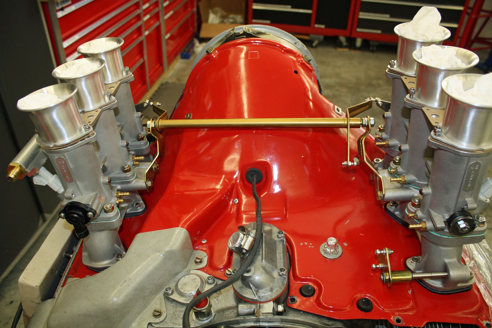
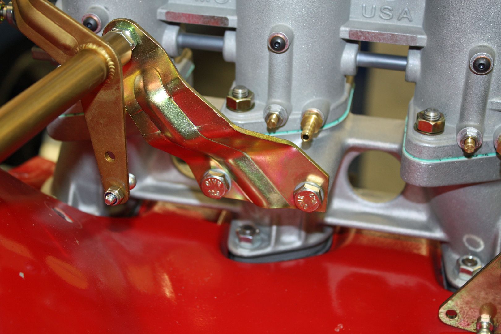
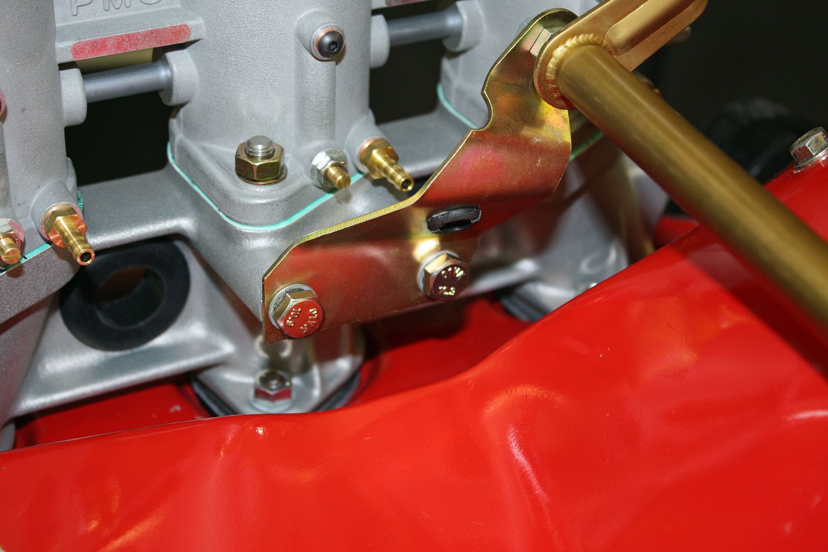
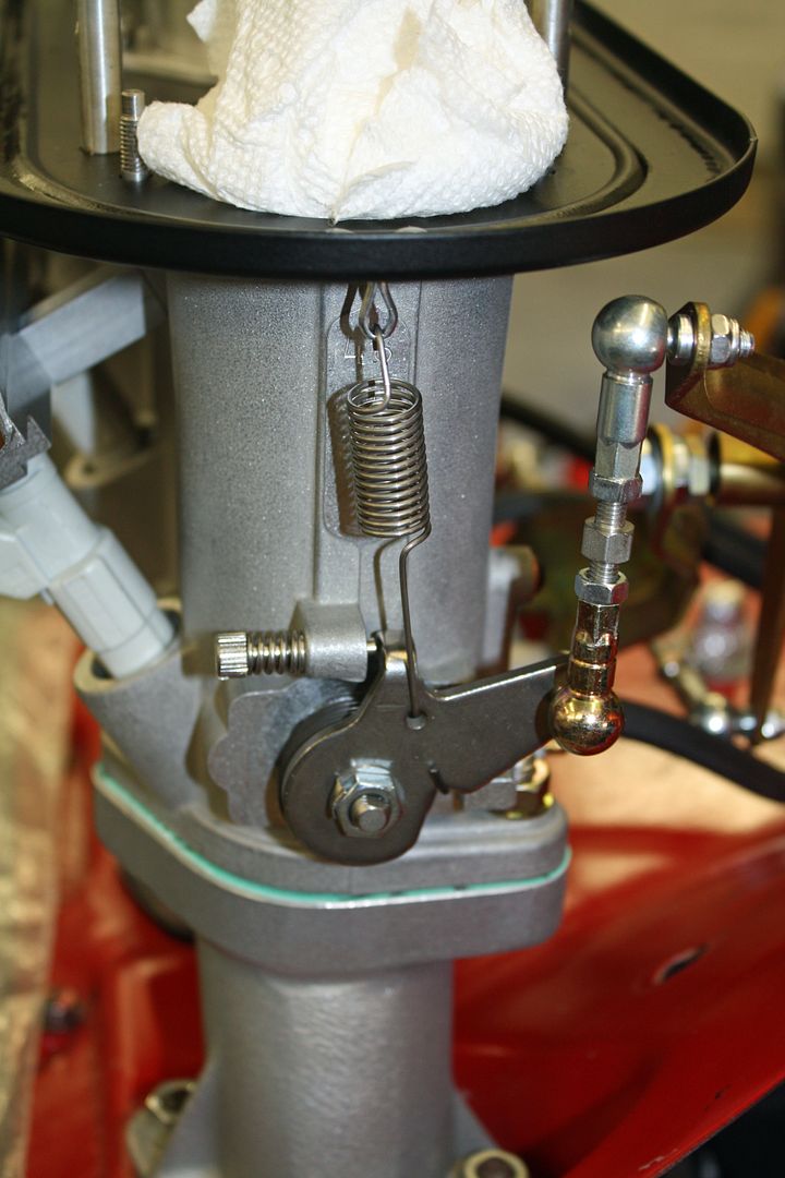
I finished up the linkage today. The left side rod ends are attached to the rod and to the throttle shaft. One begins with the rod ends at their shortest length and then two turns are added to the length. Then the rod from the bell crank to the rod can be installed. I will have to adjust it once I have the throttle pedal hooked up. The right side rod ends are adjusted so the throttle remains on the stop.
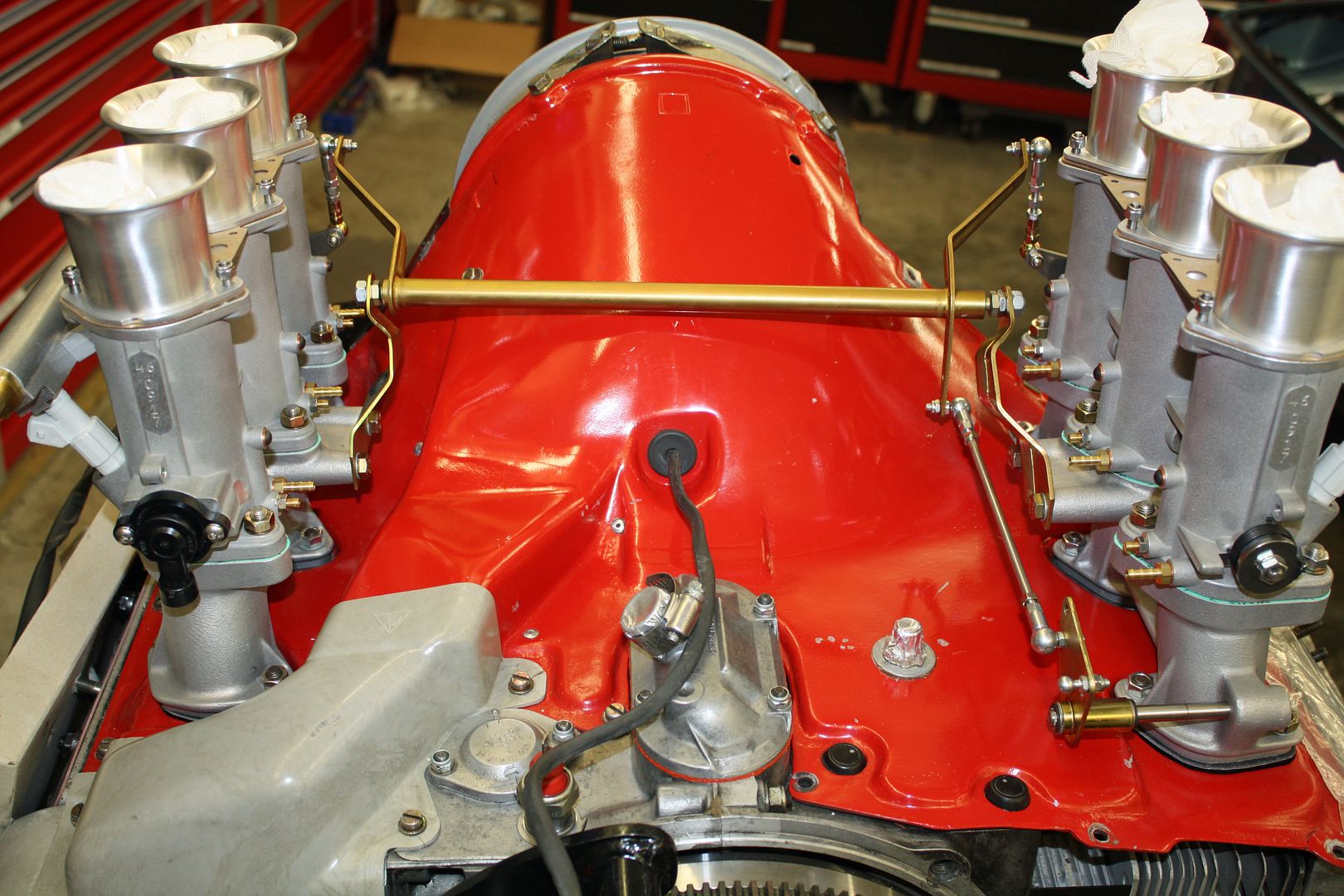
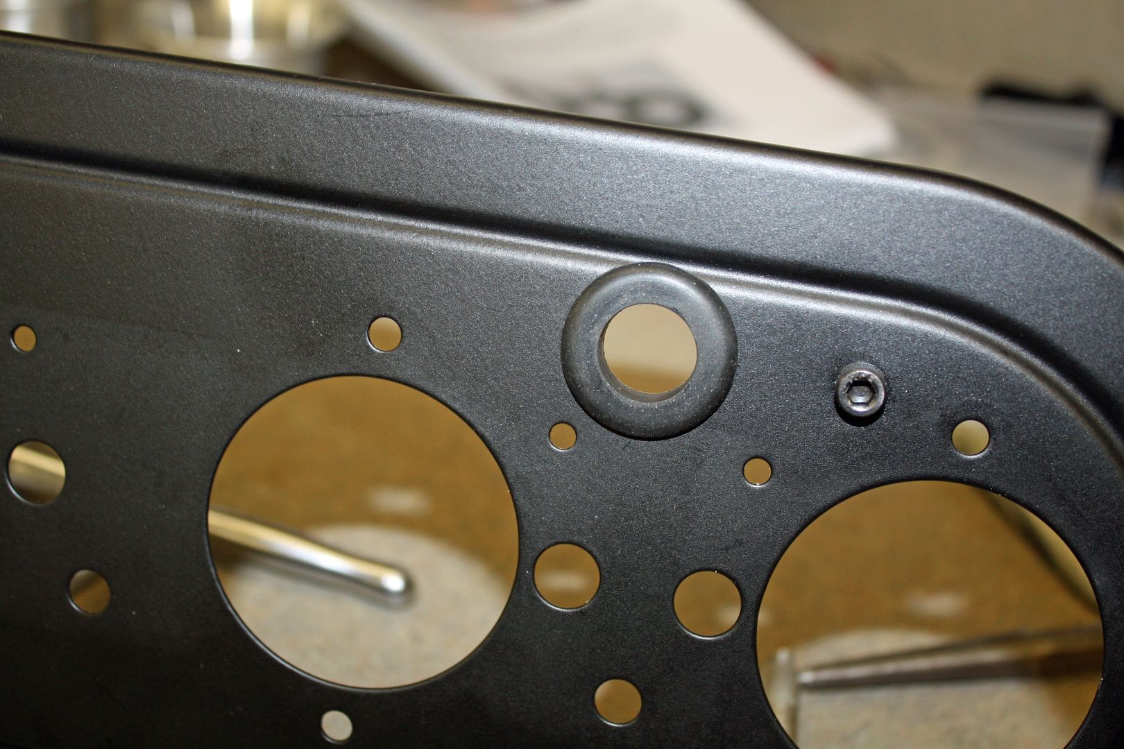
Next up was installing the air cleaners. The base plate is fastened first and then the hats.
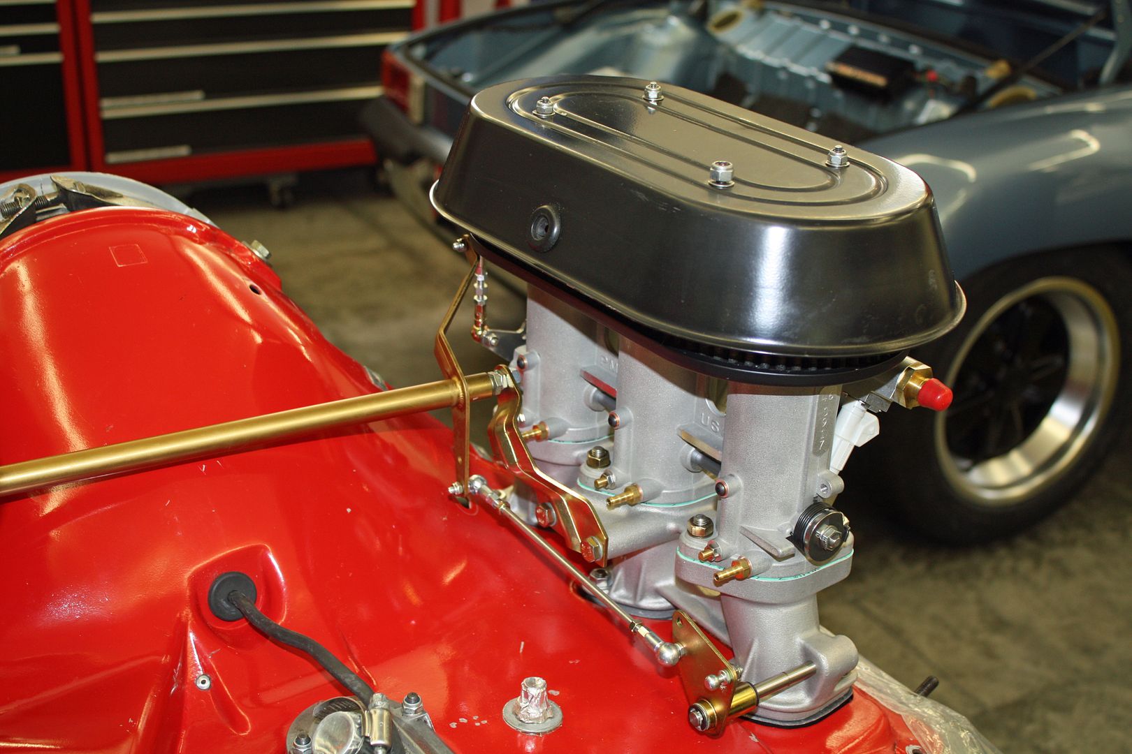
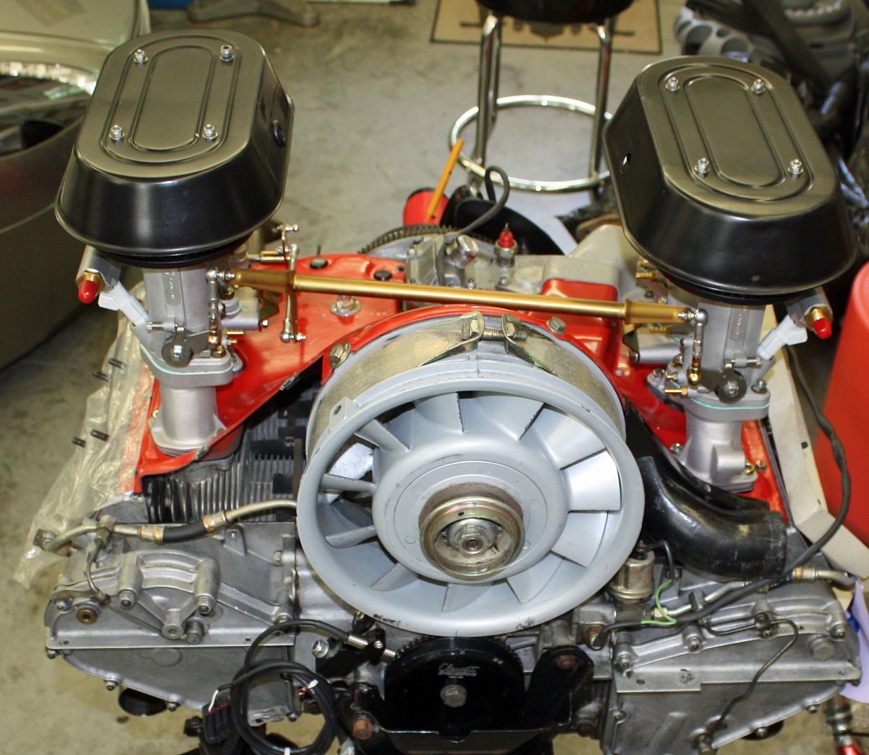
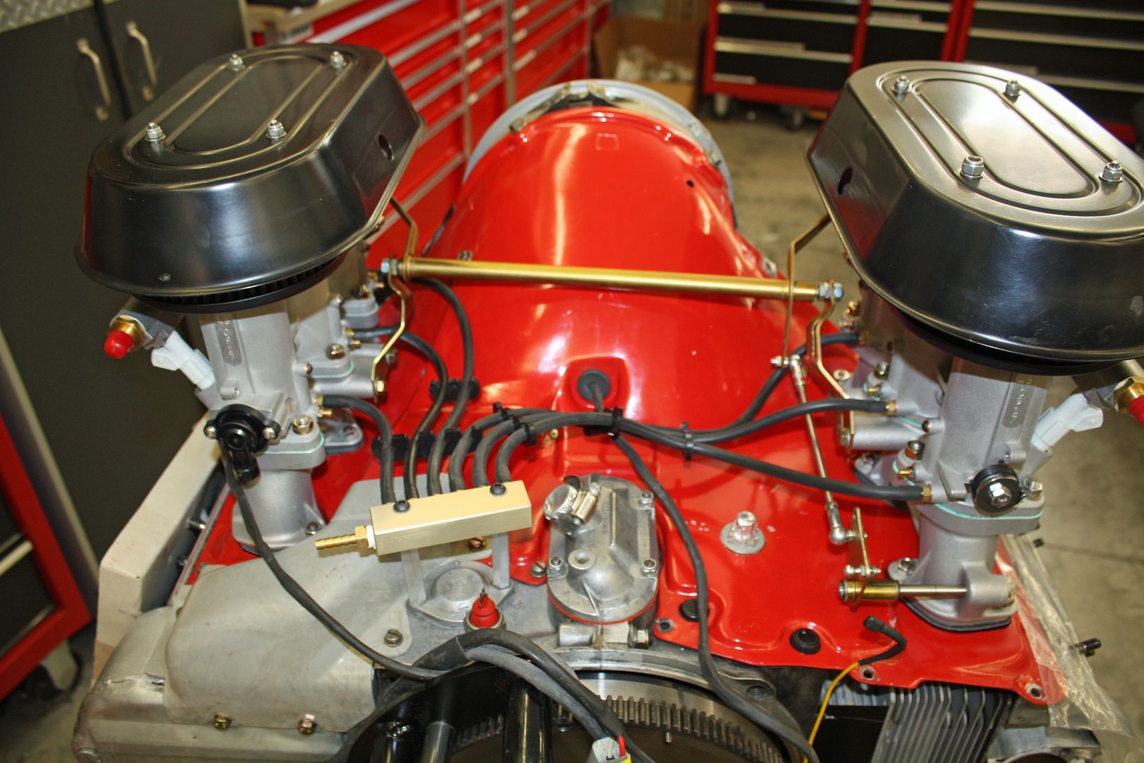
Vacuum lines have to be run from each throttle body to the vacuum manifold. It is mounted by using the studs for the oil thermostat using extensions. Some spark plug wire separators worked perfectly to route the vacuum lines.


Next up was installing the air cleaners. The base plate is fastened first and then the hats.


Vacuum lines have to be run from each throttle body to the vacuum manifold. It is mounted by using the studs for the oil thermostat using extensions. Some spark plug wire separators worked perfectly to route the vacuum lines.


 09-04-2018, 10:33 PM
#37
Racer
Thread Starter
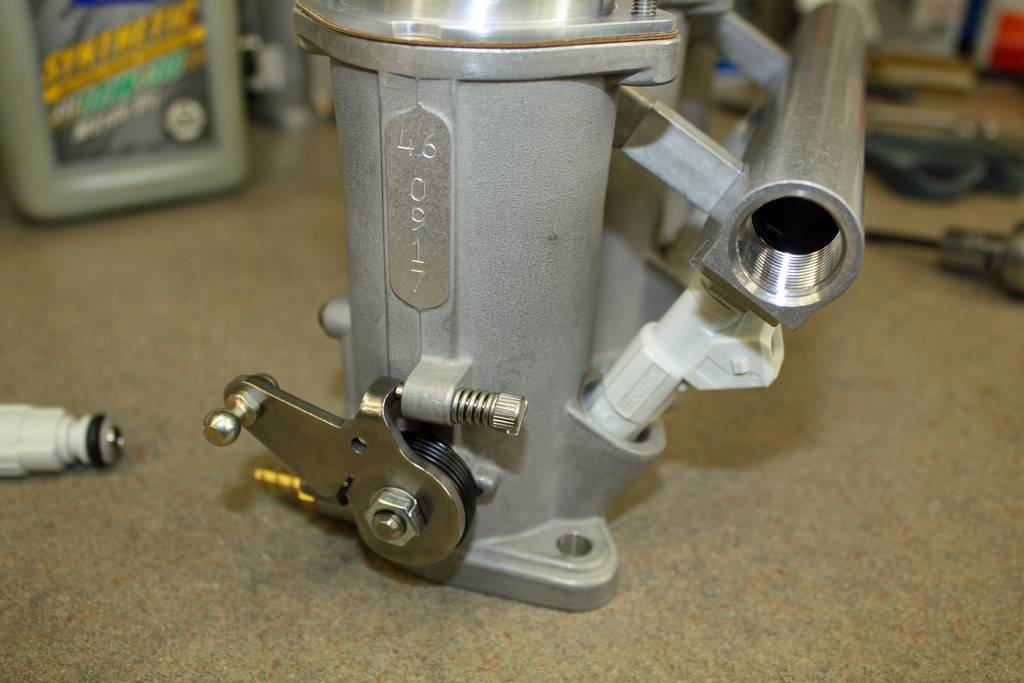
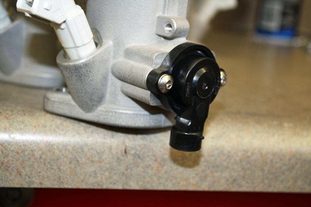
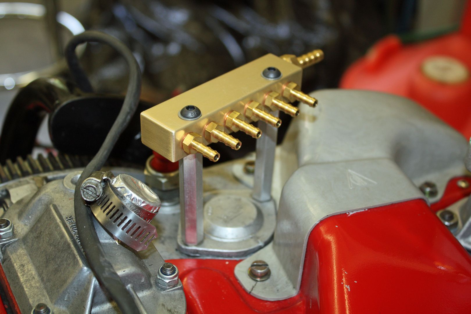
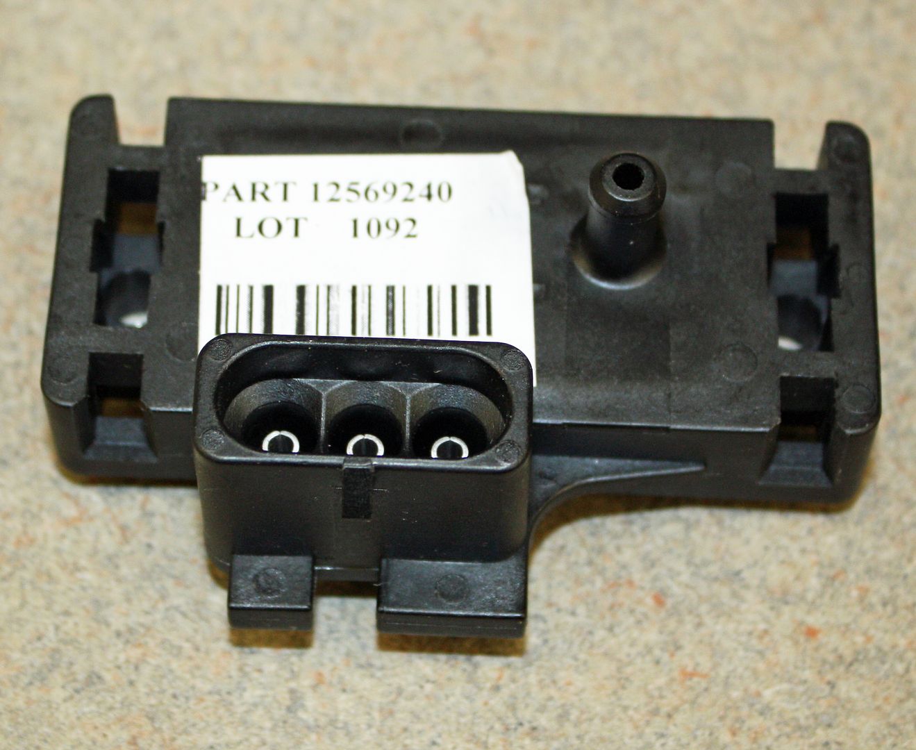
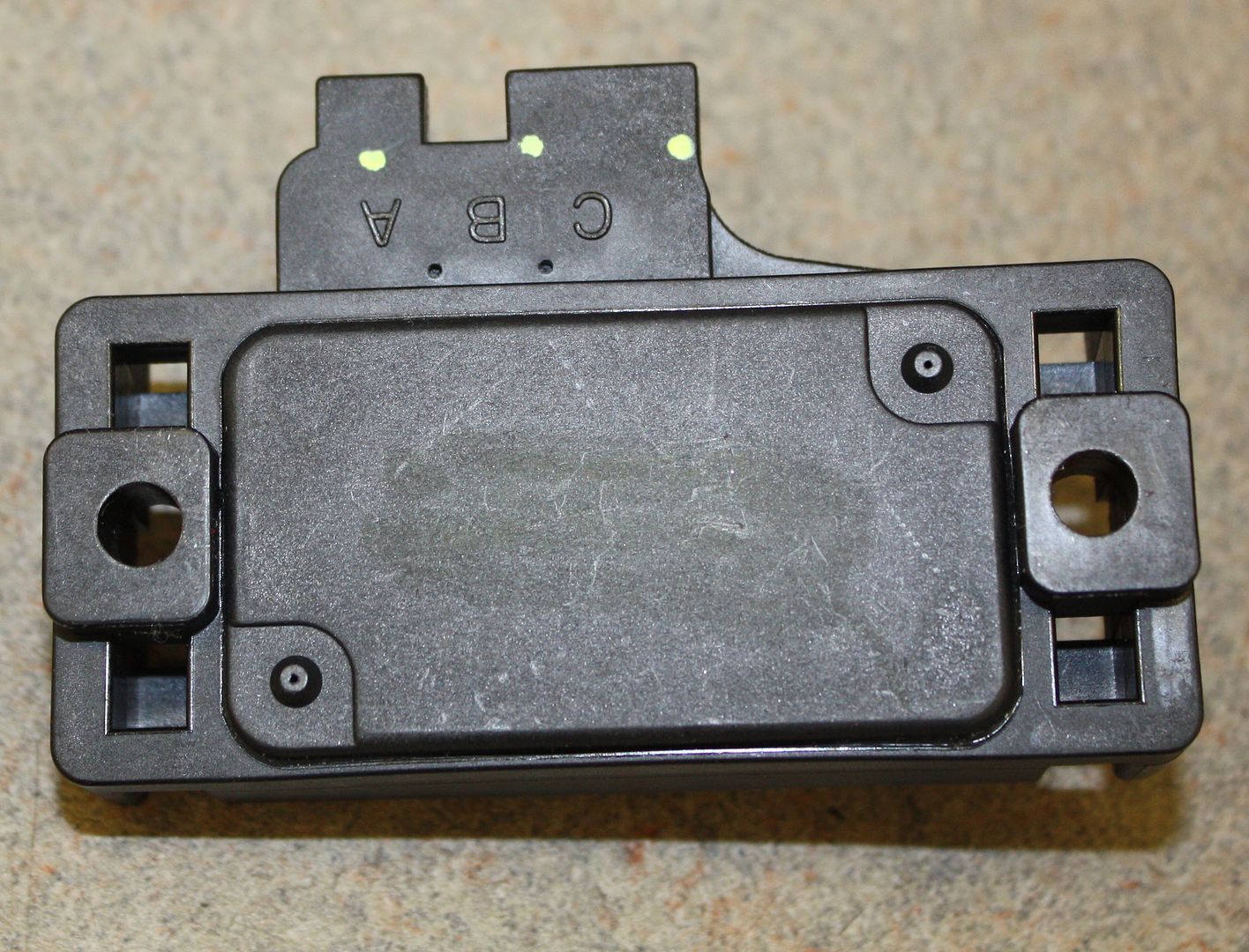
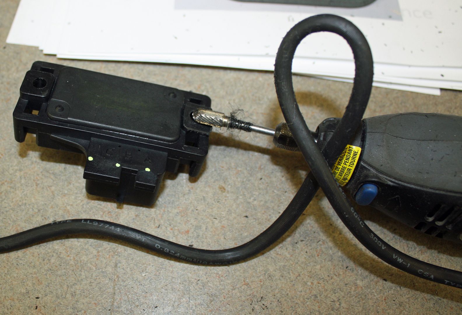
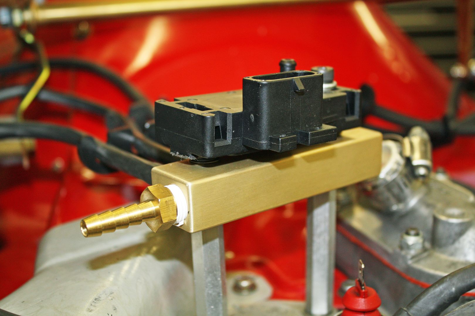
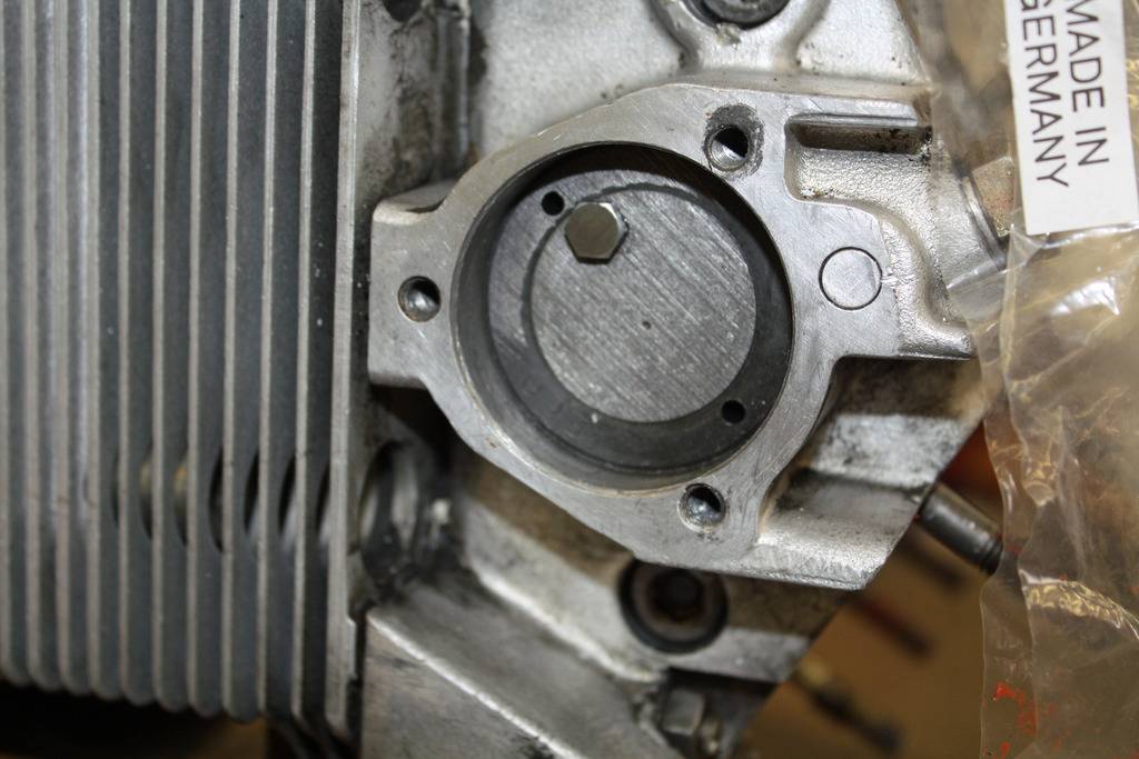
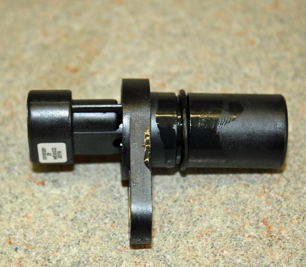
One more vacuum line needed to be run from the vacuum manifold. It went to the manifold absolute pressure (MAP) sensor. At first glance, I thought the holes would line up perfectly with the holes on the vacuum manifold. However, they were off by about an eighth of an inch. Since one bolt would be sufficient to mount the sensor, I used my Dremel to ground down the one leg on the bottom of the sensor so it would fit better on top of the vacuum manifold. Wiring to come later.
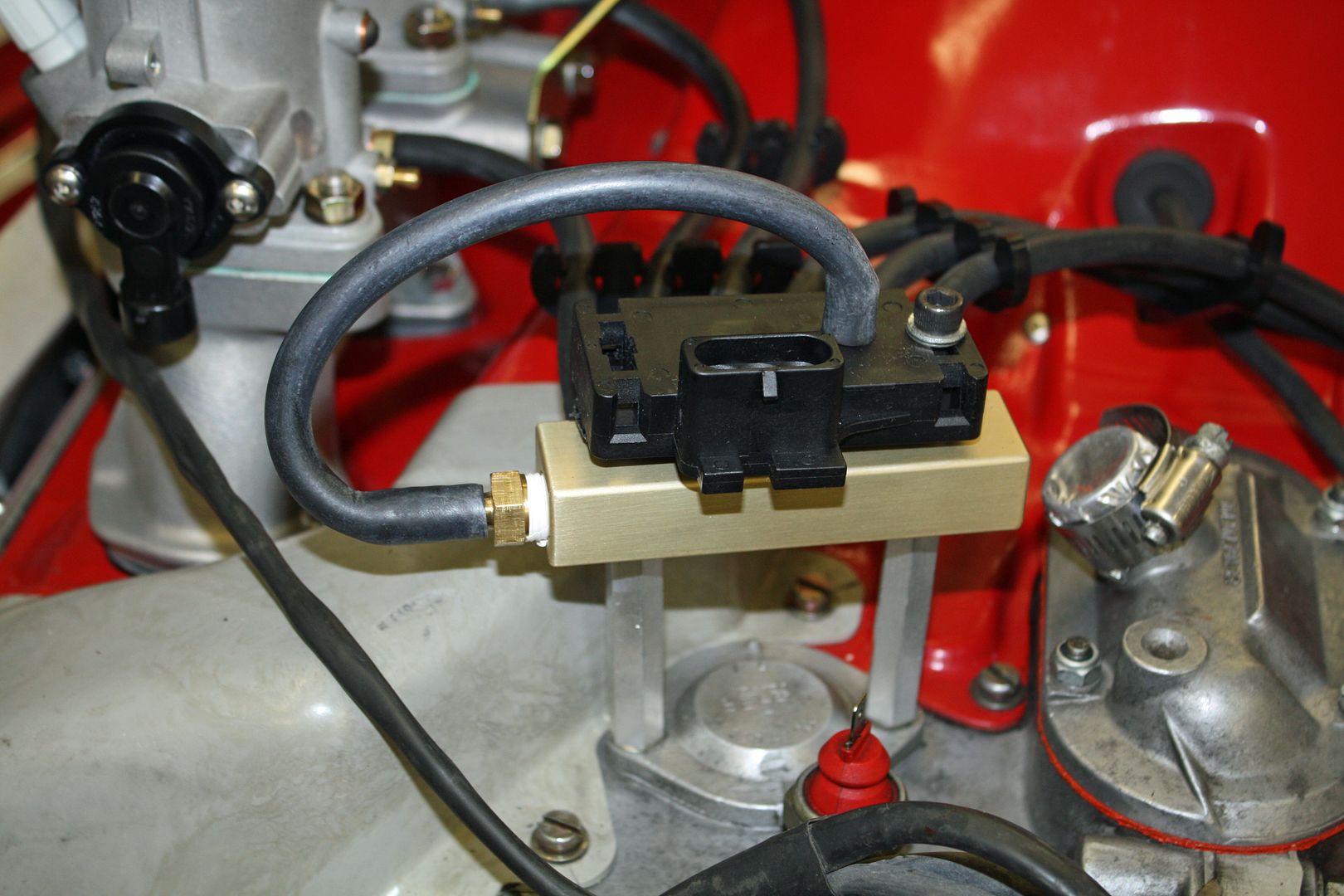
The manifold air temperature (MAT) sensor needed to be installed into the base of the air cleaner. After drilling a 7/8" hole and installing a grommet, the MAT sensor is screwed into the grommet. Sounds a little strange but it fits very securely.
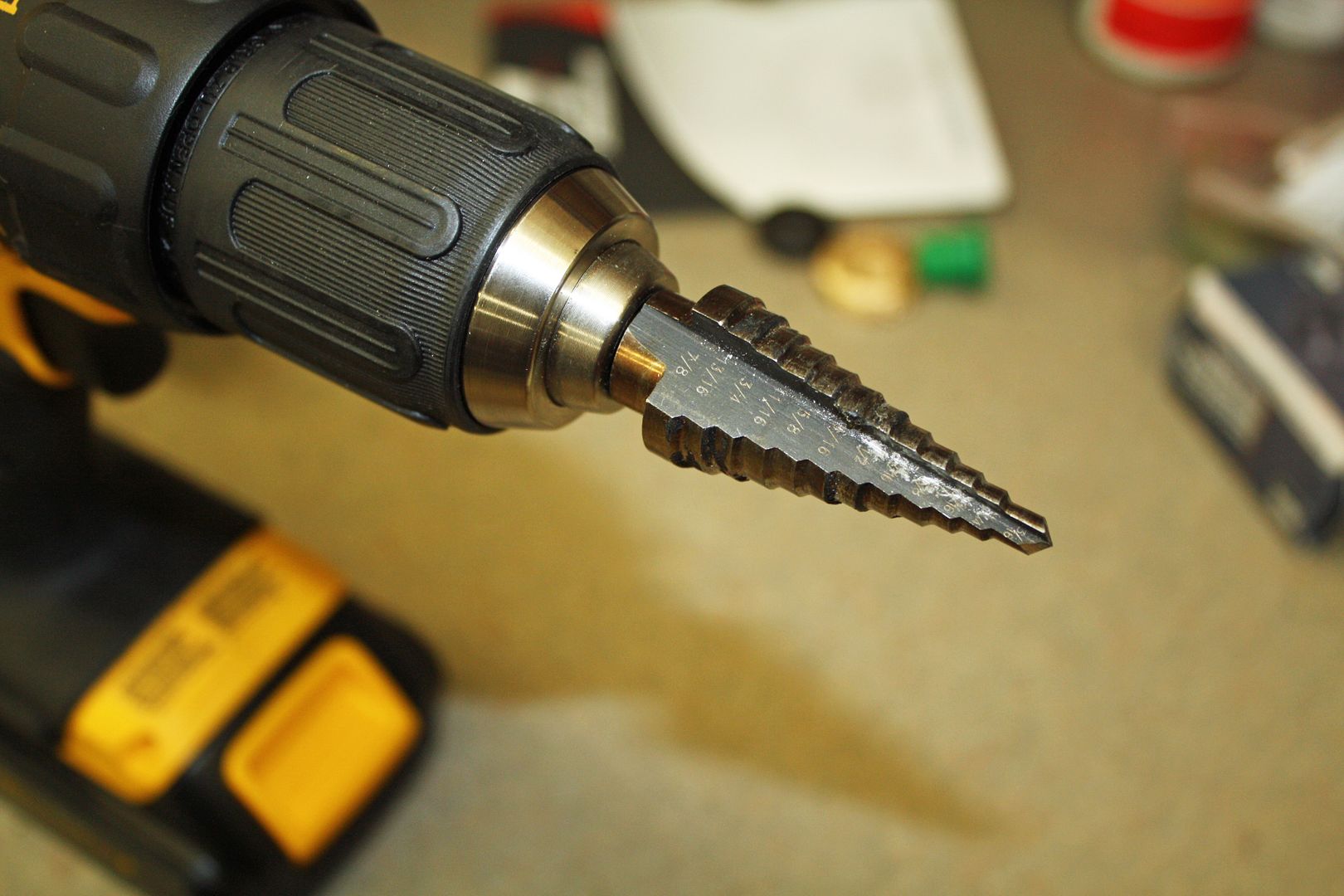
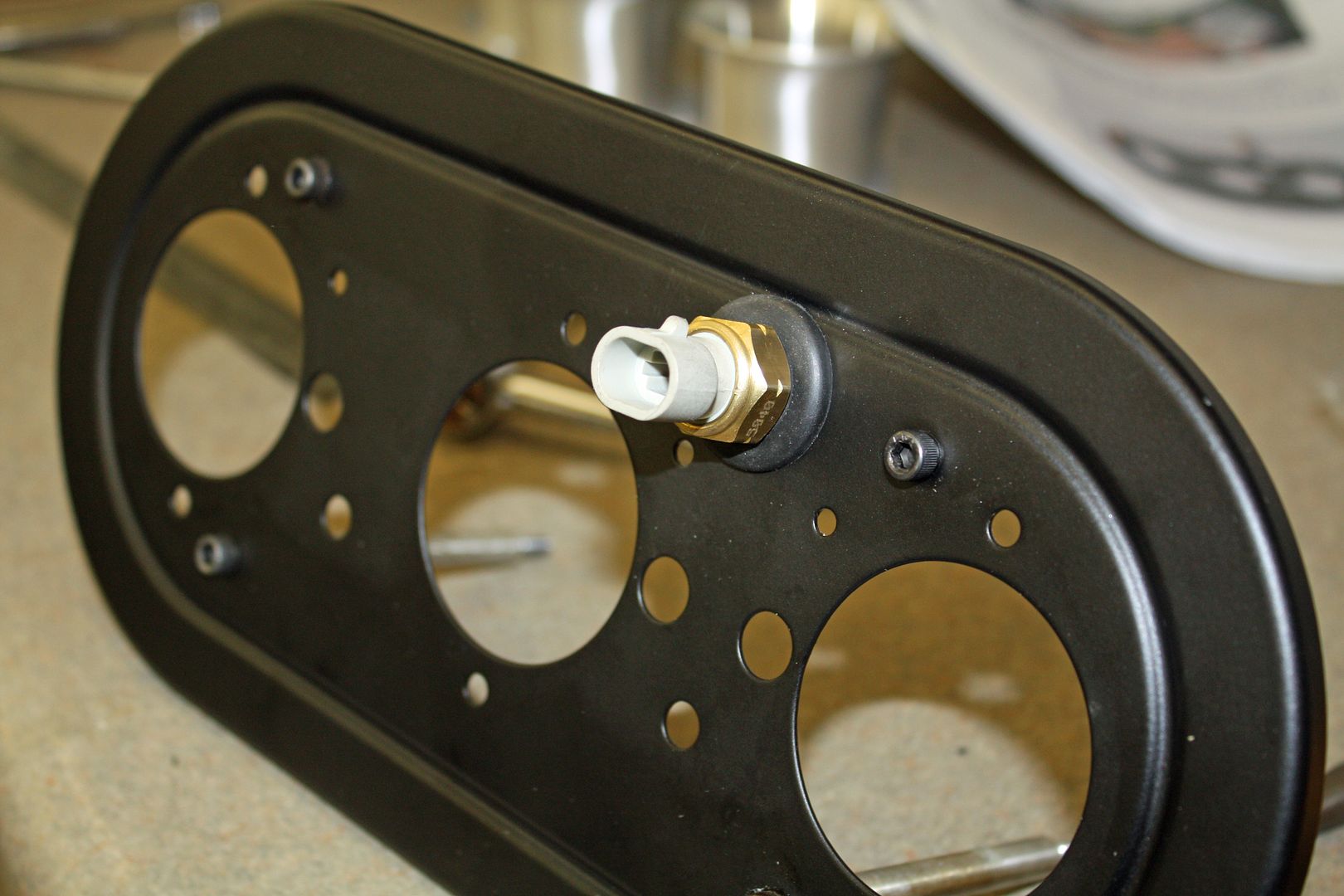
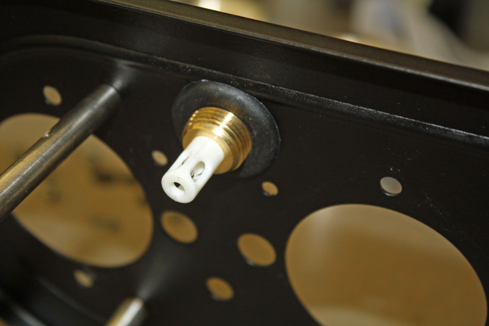


The manifold air temperature (MAT) sensor needed to be installed into the base of the air cleaner. After drilling a 7/8" hole and installing a grommet, the MAT sensor is screwed into the grommet. Sounds a little strange but it fits very securely.


 09-04-2018, 11:14 PM
#38
Racer
Thread Starter
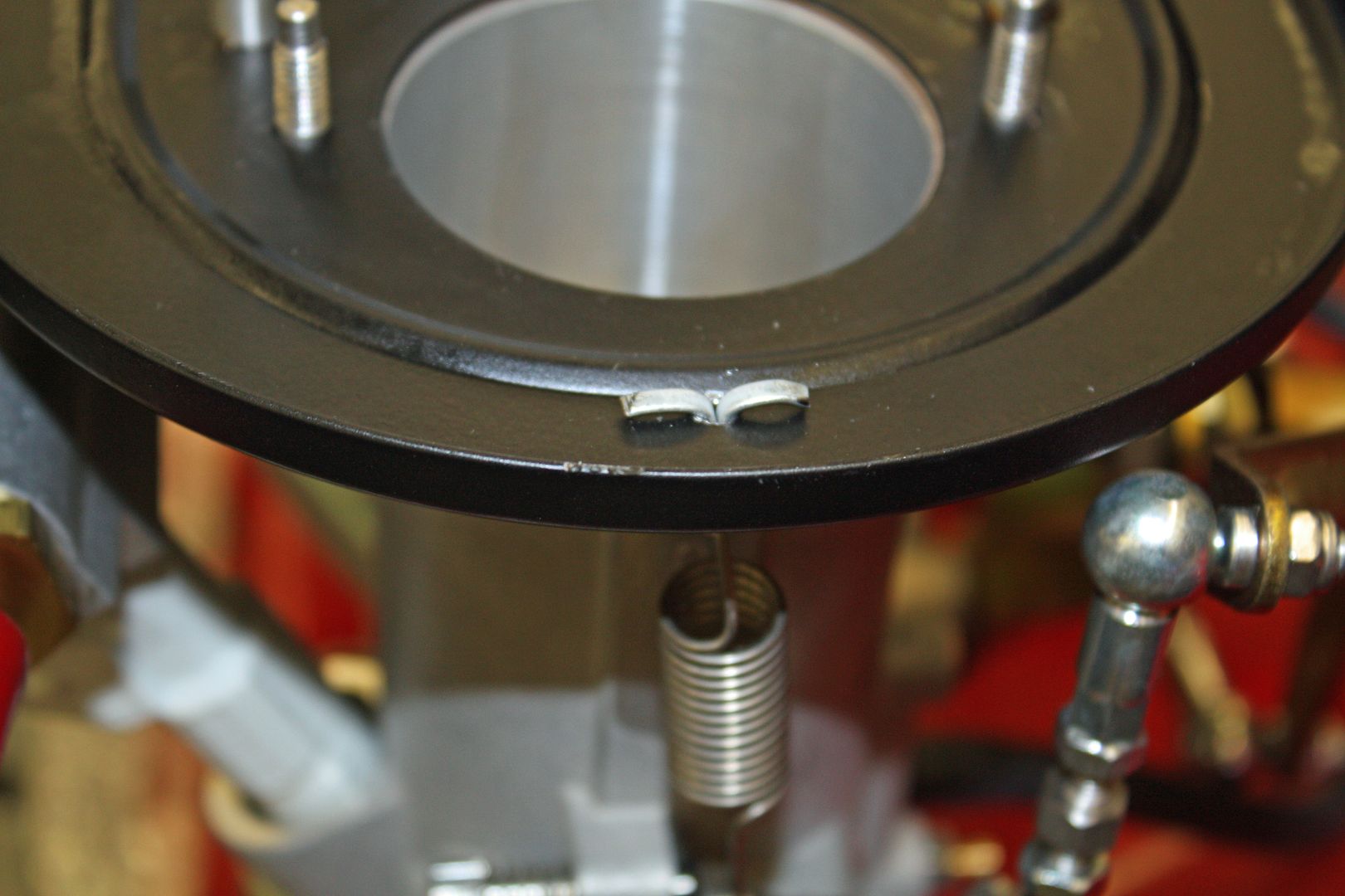
The instructions called for adding a second return spring on both throttle bodies. The recommended way was to drill a 1/8" hole into the air cleaner base. A 1/8" cotter pin is inserted from the bottom and spread out on the top of the air cleaner base. The excess metal on the cotter pin is cut away. The bottom of the cotter pin becomes the eye for the upper mount for the return spring.
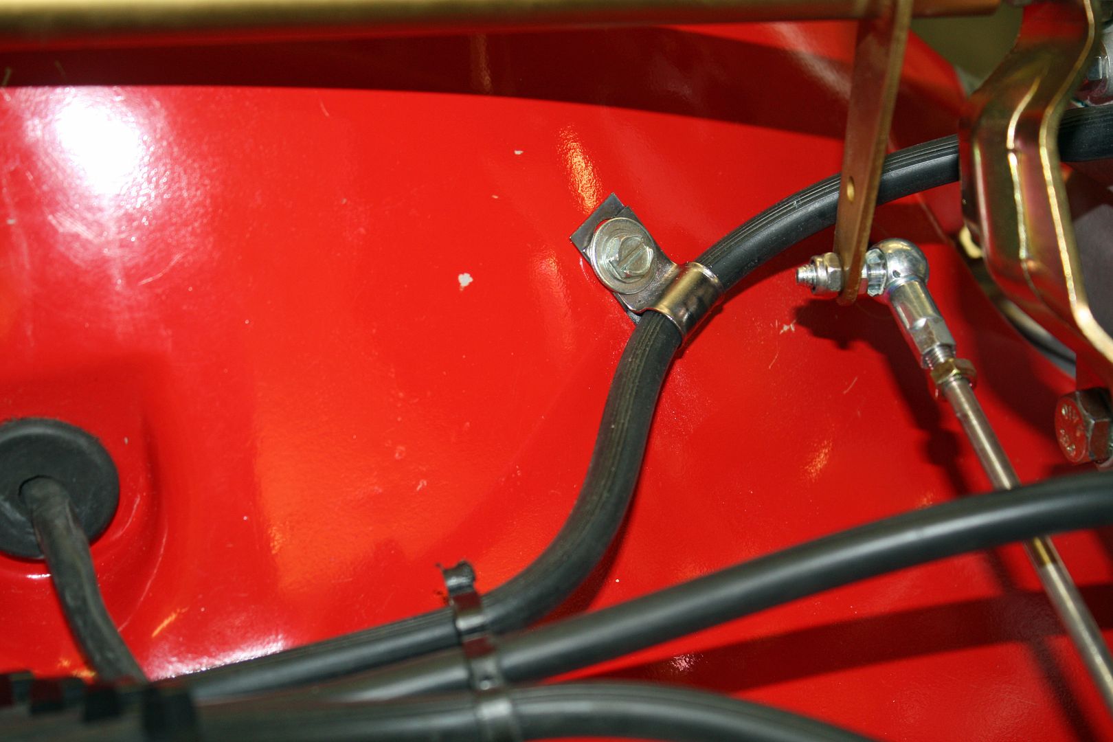
Because I was concerned about the vacuum line on the left side being close to the throttle linkage, I decided to clamp it to the fan shroud.
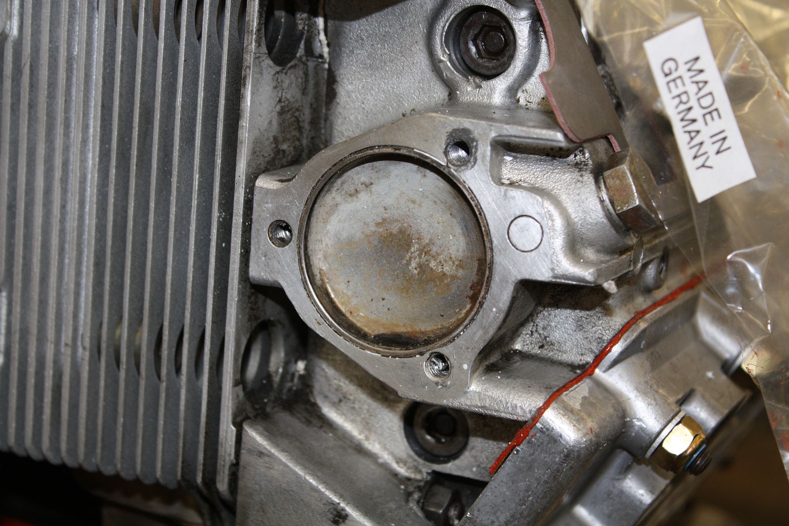
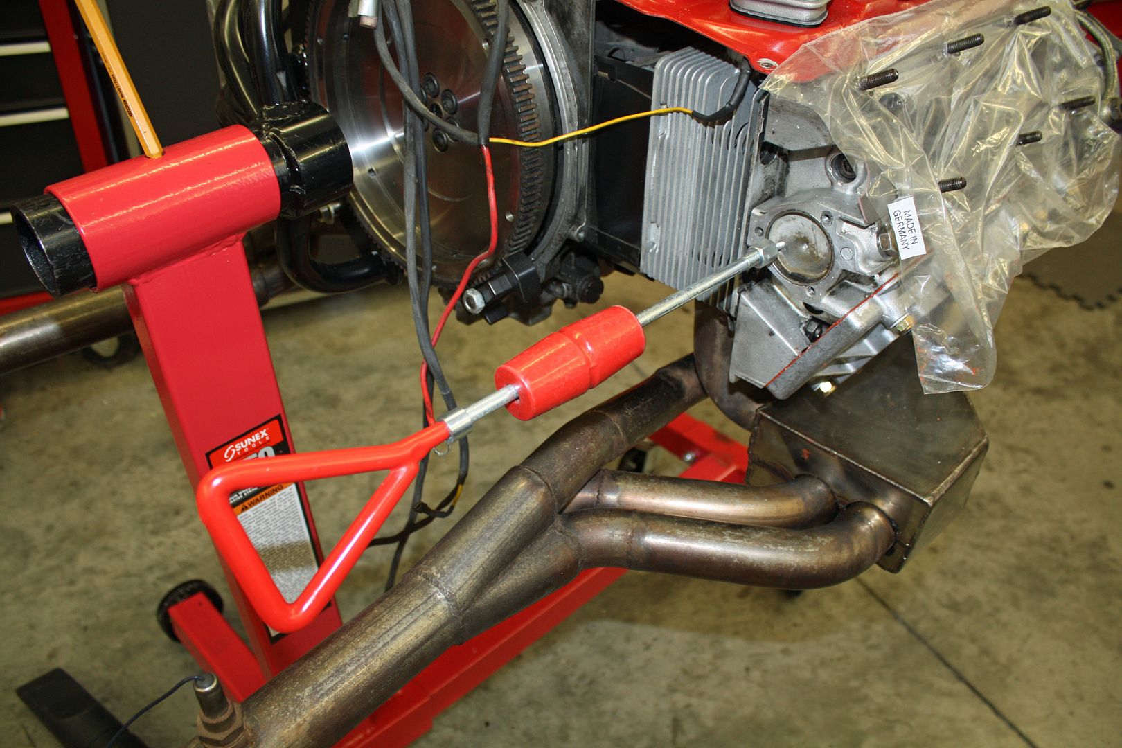
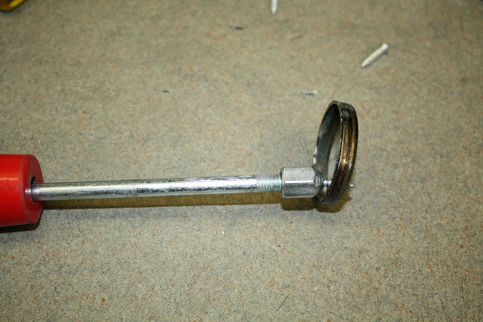
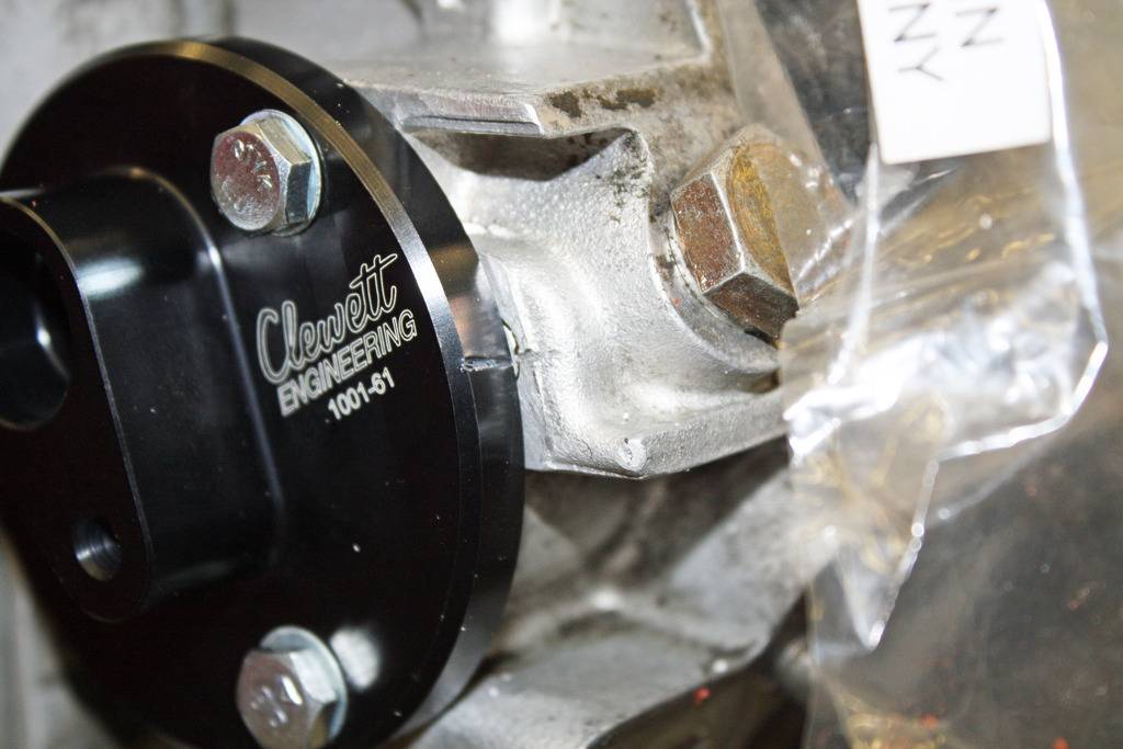
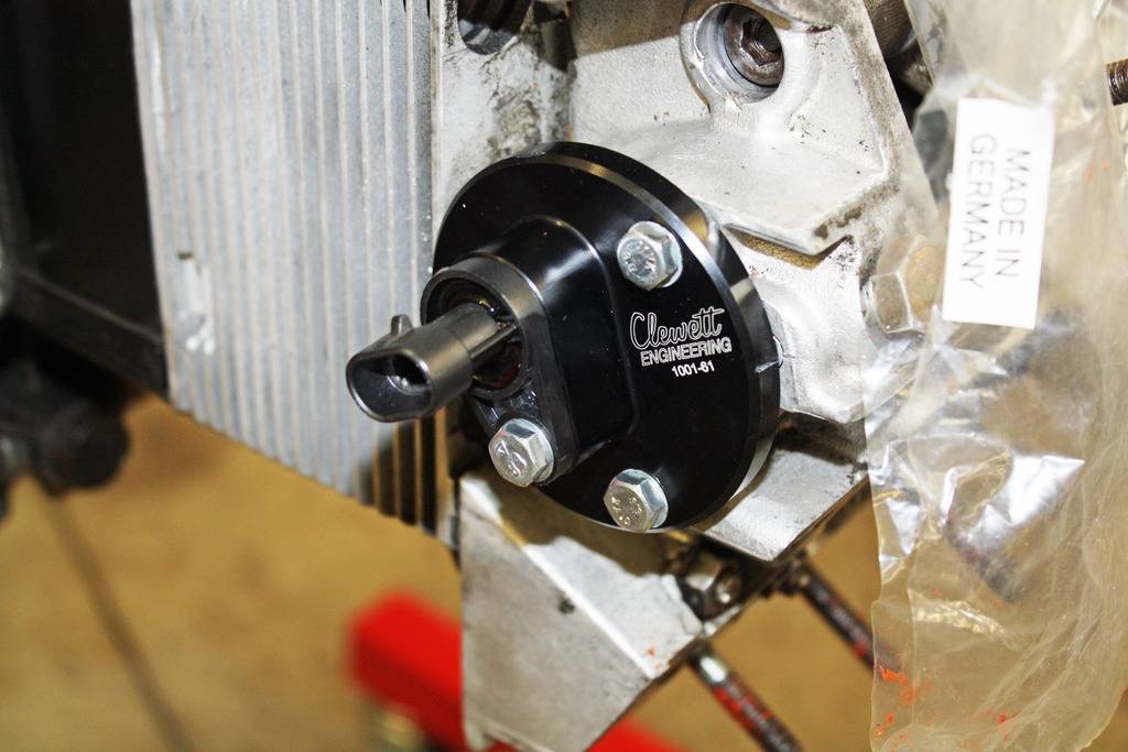
To install the cam sync adapter, the plug on the end of the cam housing must be removed. As recommended, I used a dent puller for removal. I drilled a small hole off to one side, inserted a screw into the holder and screwed it into the plug. By pulling on the slide weight on the puller, the cap was easily removed. I placed some grease on the drill bit to catch most of the shavings.
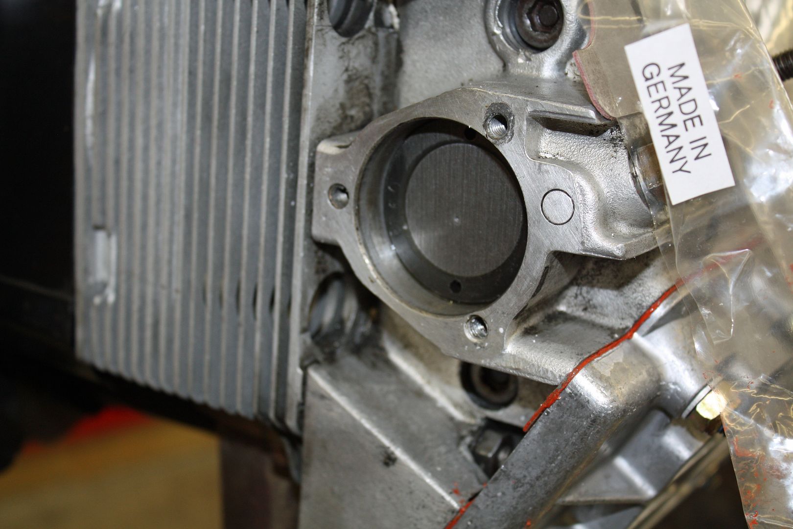
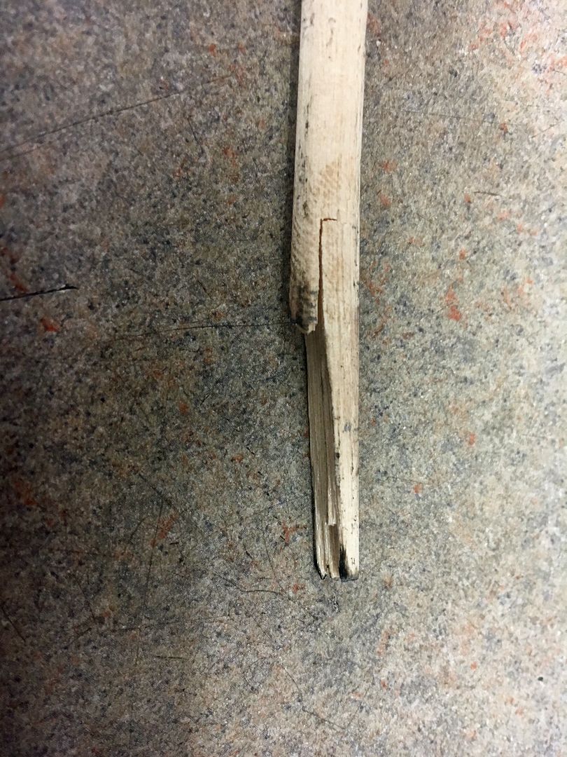
The next instruction said Rotate the engine through a cycle stopping 90 degrees before Z1 on the compression stroke." When I had installed the new fan pulley, I had the engine set at TDC. As I began to rotate the motor, I was interrupted. When I came back I realized that I didn't know where I was on the cycle. No problem. As I have done in the past, I would pull plug #1, insert a 1/4" wooden dowel, mark it and then see when it was pushed out the maximum at Z1. And this is when my day went sour. After cranking through a couple cylinders, the dowel was snagged by something and a piece was broken off. The broken off piece was about an inch long and about half the dowel width.
I got a piece of clear hose and attached it to my shop vac and tried to suck it out. When that didn't work, I called Richard Clewett at Clewett Engineering, the guy who sold me the EFI kit. His first thought was to see if the #1 exhaust valve was open. If so, he recommended using air to blow it out. Since the exhaust was on, I removed it or else I wouldn't know if anything came out. The exhaust valve was open. Blowing air into it do not work. I have an engine camera scope. After inserting it through the plug hole, I could not see the piece of wood. I also looked up through the open valve and it was not visible there.
Since my skills stop at building motors, I will have to take the motor somewhere and have the head removed to see what is going on. Not the way I wanted to end the day but sometimes things happen. My son works with Todd Holbert (Al"s son) at Toyota Racing Development (TRD). My son texted him about shops that he would recommend. I will be contacting them tomorrow.


Because I was concerned about the vacuum line on the left side being close to the throttle linkage, I decided to clamp it to the fan shroud.

To install the cam sync adapter, the plug on the end of the cam housing must be removed. As recommended, I used a dent puller for removal. I drilled a small hole off to one side, inserted a screw into the holder and screwed it into the plug. By pulling on the slide weight on the puller, the cap was easily removed. I placed some grease on the drill bit to catch most of the shavings.


The next instruction said Rotate the engine through a cycle stopping 90 degrees before Z1 on the compression stroke." When I had installed the new fan pulley, I had the engine set at TDC. As I began to rotate the motor, I was interrupted. When I came back I realized that I didn't know where I was on the cycle. No problem. As I have done in the past, I would pull plug #1, insert a 1/4" wooden dowel, mark it and then see when it was pushed out the maximum at Z1. And this is when my day went sour. After cranking through a couple cylinders, the dowel was snagged by something and a piece was broken off. The broken off piece was about an inch long and about half the dowel width.

I got a piece of clear hose and attached it to my shop vac and tried to suck it out. When that didn't work, I called Richard Clewett at Clewett Engineering, the guy who sold me the EFI kit. His first thought was to see if the #1 exhaust valve was open. If so, he recommended using air to blow it out. Since the exhaust was on, I removed it or else I wouldn't know if anything came out. The exhaust valve was open. Blowing air into it do not work. I have an engine camera scope. After inserting it through the plug hole, I could not see the piece of wood. I also looked up through the open valve and it was not visible there.
Since my skills stop at building motors, I will have to take the motor somewhere and have the head removed to see what is going on. Not the way I wanted to end the day but sometimes things happen. My son works with Todd Holbert (Al"s son) at Toyota Racing Development (TRD). My son texted him about shops that he would recommend. I will be contacting them tomorrow.
09-05-2018, 07:15 PM
#39
Racer
Thread Starter
Today was a better day. I removed the left side throttle bodies and manifolds so I could see in through the intake valve for cylinder #1. I rotated the engine so the valve was open. Using my camera scope I could see nothing. I checked again with the exhaust valve open and saw nothing again. With the piston recessed in the cylinder, I was able to look completely around it and nothing showed. I could see that there was nothing caught by the valves. So, I am convinced that there is nothing in that cylinder.
When I hooked up my shop vac yesterday, I used a clear tube to suck from the spark plug hole so I could see anything that might be vacuumed out. I was looking for a piece that was the size of the piece that was missing. However, the dowel is made from some really soft wood and it might have been crushed when it was caught by a valve. So there may have been fragments that were sucked out that I didn't see.
I rotated the motor through a complete cycle and double checked my valve clearances.
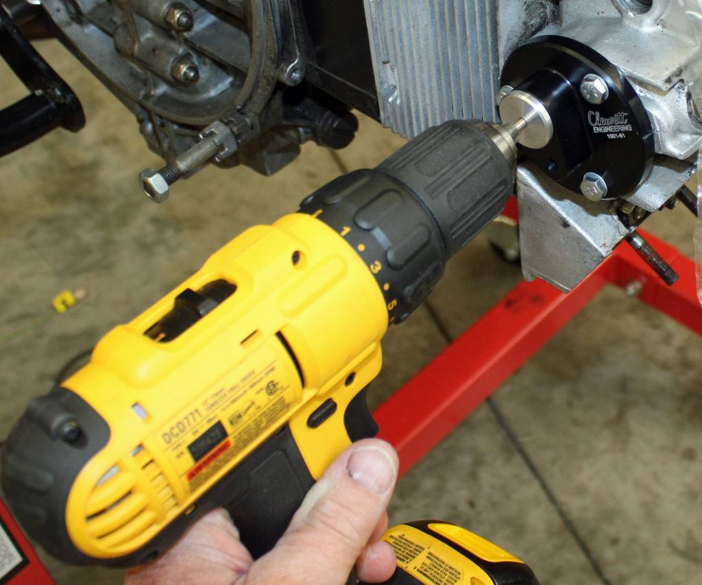
So I got back to doing the job that started all of this commotion yesterday...installing the cam sync adapter. The motor is to be in the position with Z1 at 90 degrees before TDC on the cam pulley.. Once I had that set, the next step is to mount the adapter without the gasket. It is recommended to add a witness mark at this time.
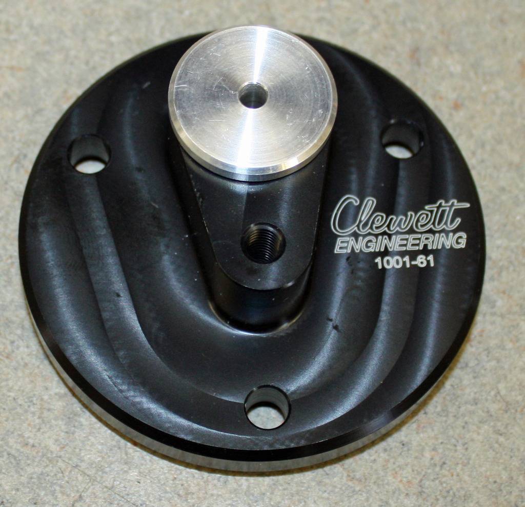
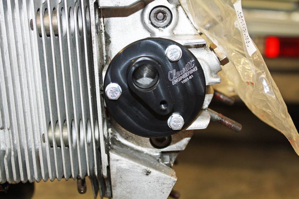
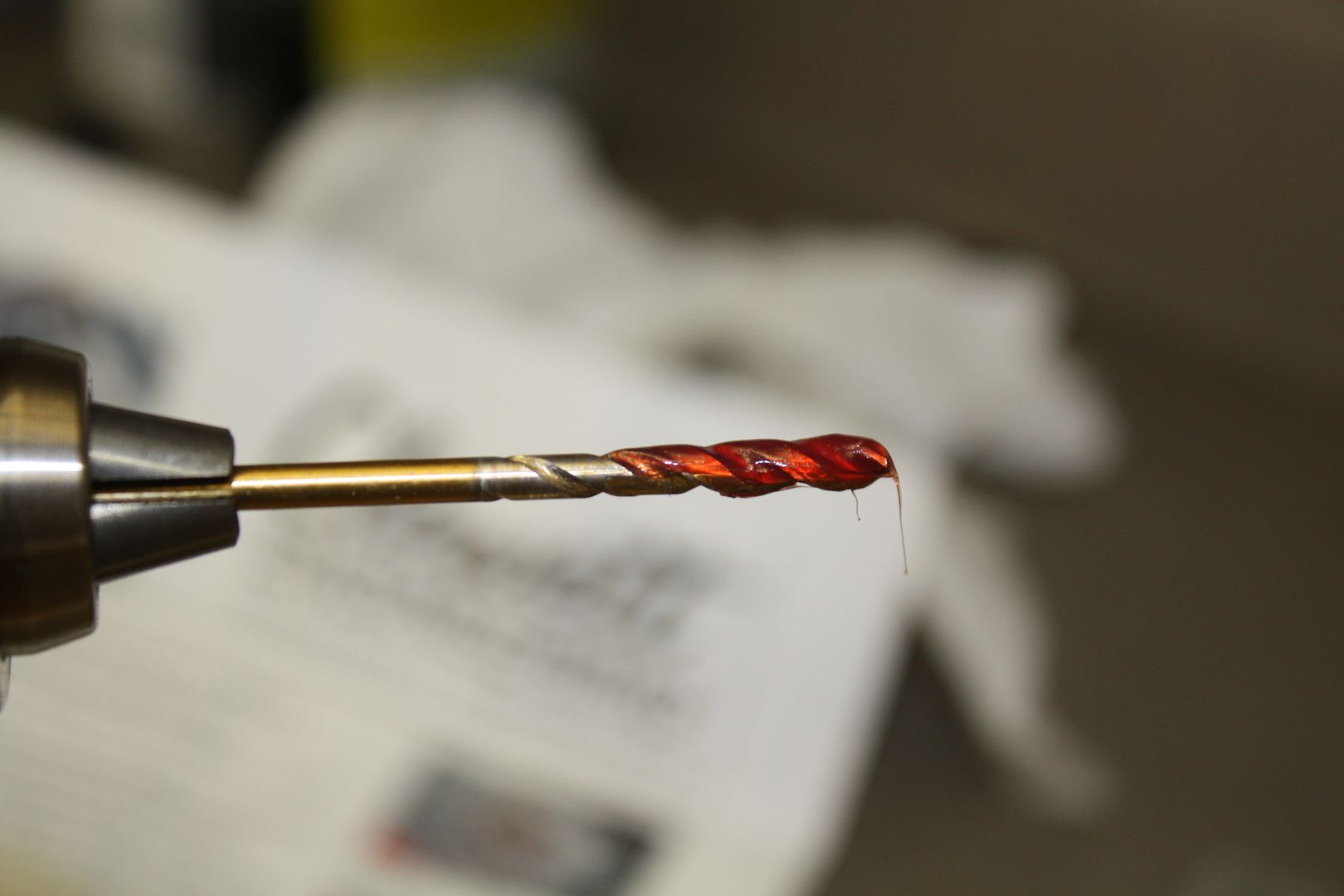
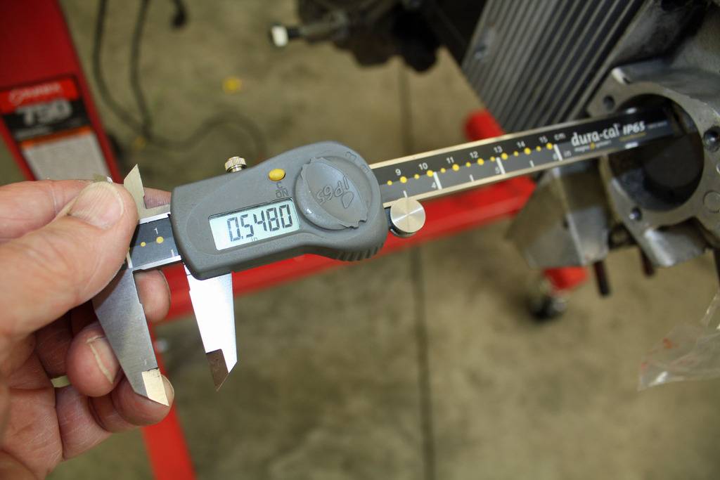
With it mounted, you insert the drill bushing using a 4.2mm drill bit. Since I couldn't find anyone handling metric drill bits, the next closest that fits into the drill bushing is 5/32. A little over 1/2" deep hole is drilled into the end of the cam. That hole is tapped with a M5-0.8 thread. The supplied bolt is then bolted into the hole with the head being flush with the cam surface using red loctite. The adapter is then mounted with the gasket. You then check the distance from the cam sensor mounting surface to the top of the M5 bolt. The distance should be 33.0-33.5mm (1.300-1.320). Mine was in that range. Now the cam sensor can be mounted to the adapter. It reads the bolt head as the cam rotates.
When I hooked up my shop vac yesterday, I used a clear tube to suck from the spark plug hole so I could see anything that might be vacuumed out. I was looking for a piece that was the size of the piece that was missing. However, the dowel is made from some really soft wood and it might have been crushed when it was caught by a valve. So there may have been fragments that were sucked out that I didn't see.
I rotated the motor through a complete cycle and double checked my valve clearances.
So I got back to doing the job that started all of this commotion yesterday...installing the cam sync adapter. The motor is to be in the position with Z1 at 90 degrees before TDC on the cam pulley.. Once I had that set, the next step is to mount the adapter without the gasket. It is recommended to add a witness mark at this time.


With it mounted, you insert the drill bushing using a 4.2mm drill bit. Since I couldn't find anyone handling metric drill bits, the next closest that fits into the drill bushing is 5/32. A little over 1/2" deep hole is drilled into the end of the cam. That hole is tapped with a M5-0.8 thread. The supplied bolt is then bolted into the hole with the head being flush with the cam surface using red loctite. The adapter is then mounted with the gasket. You then check the distance from the cam sensor mounting surface to the top of the M5 bolt. The distance should be 33.0-33.5mm (1.300-1.320). Mine was in that range. Now the cam sensor can be mounted to the adapter. It reads the bolt head as the cam rotates.


 09-06-2018, 04:53 PM
#40
Racer
Thread Starter
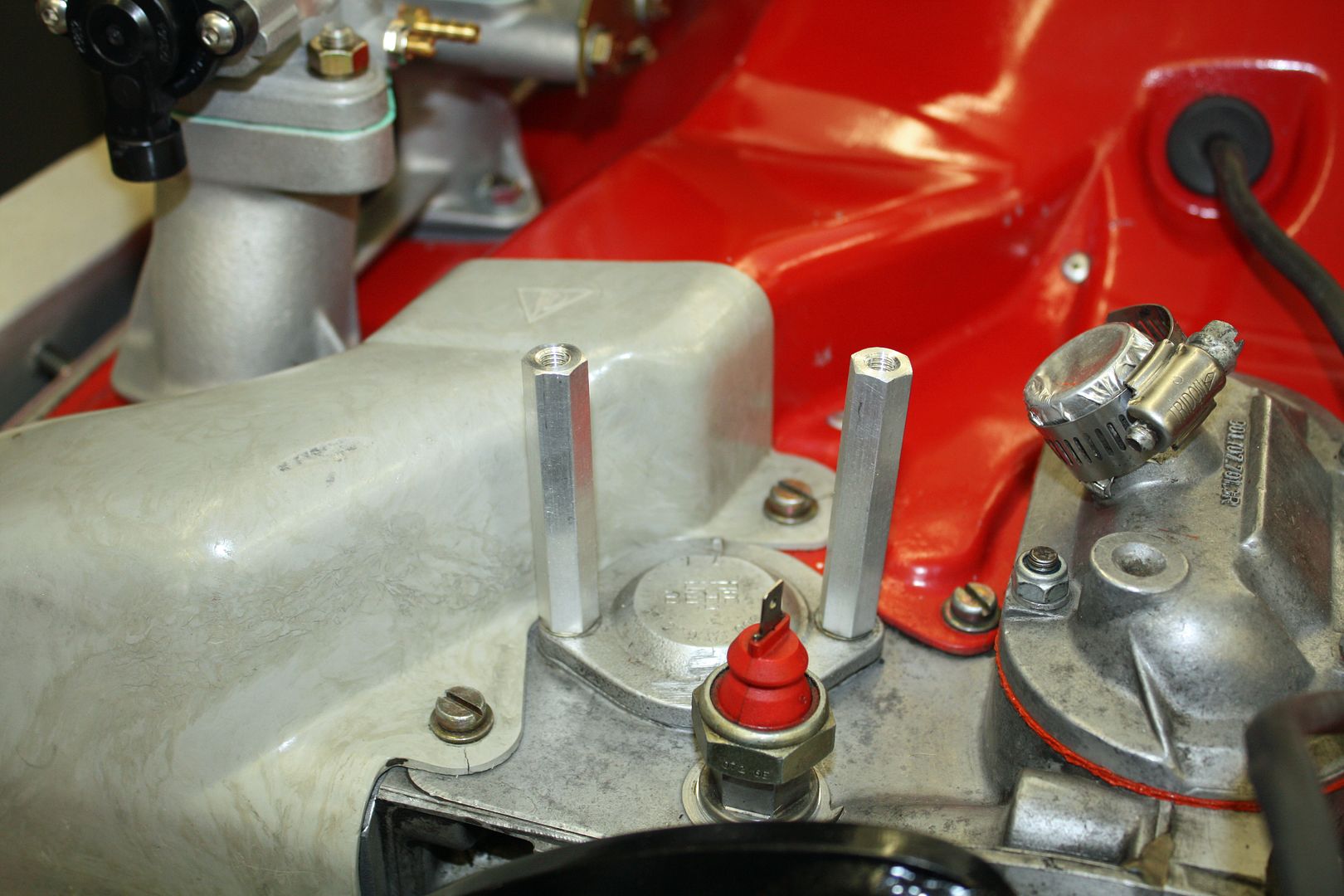
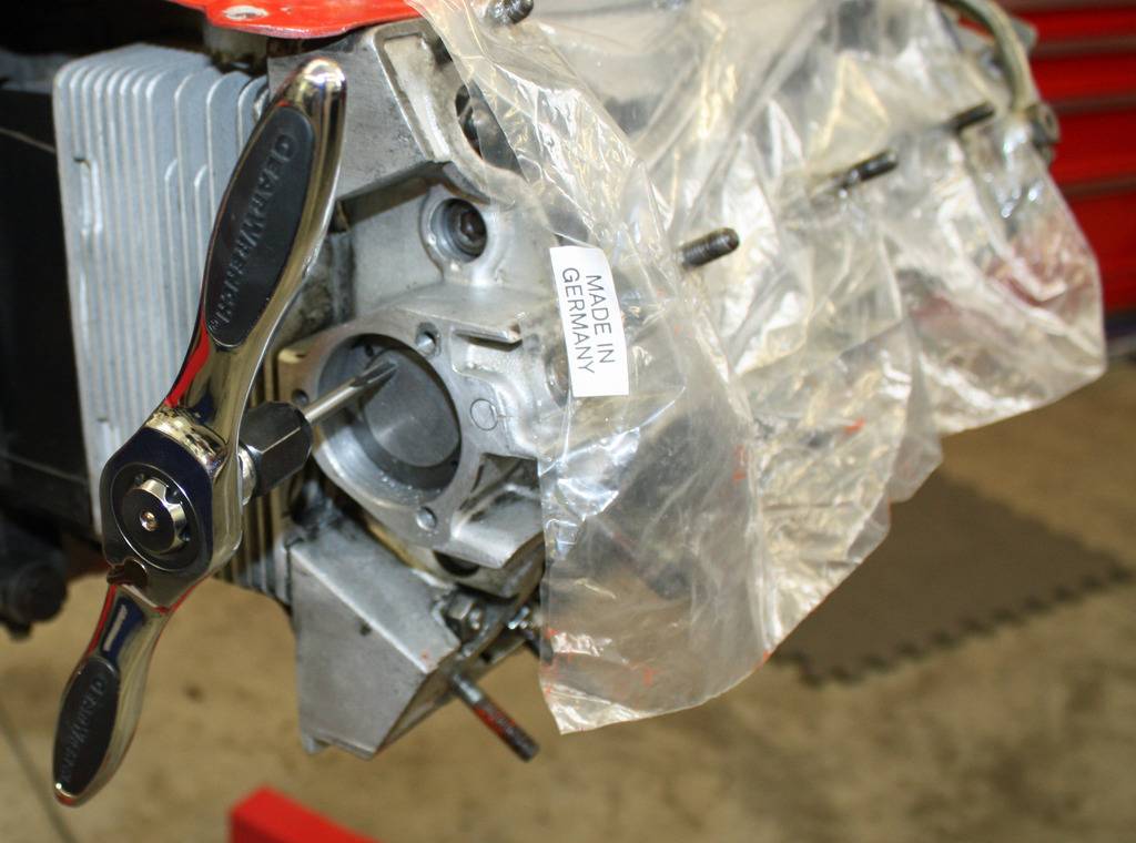
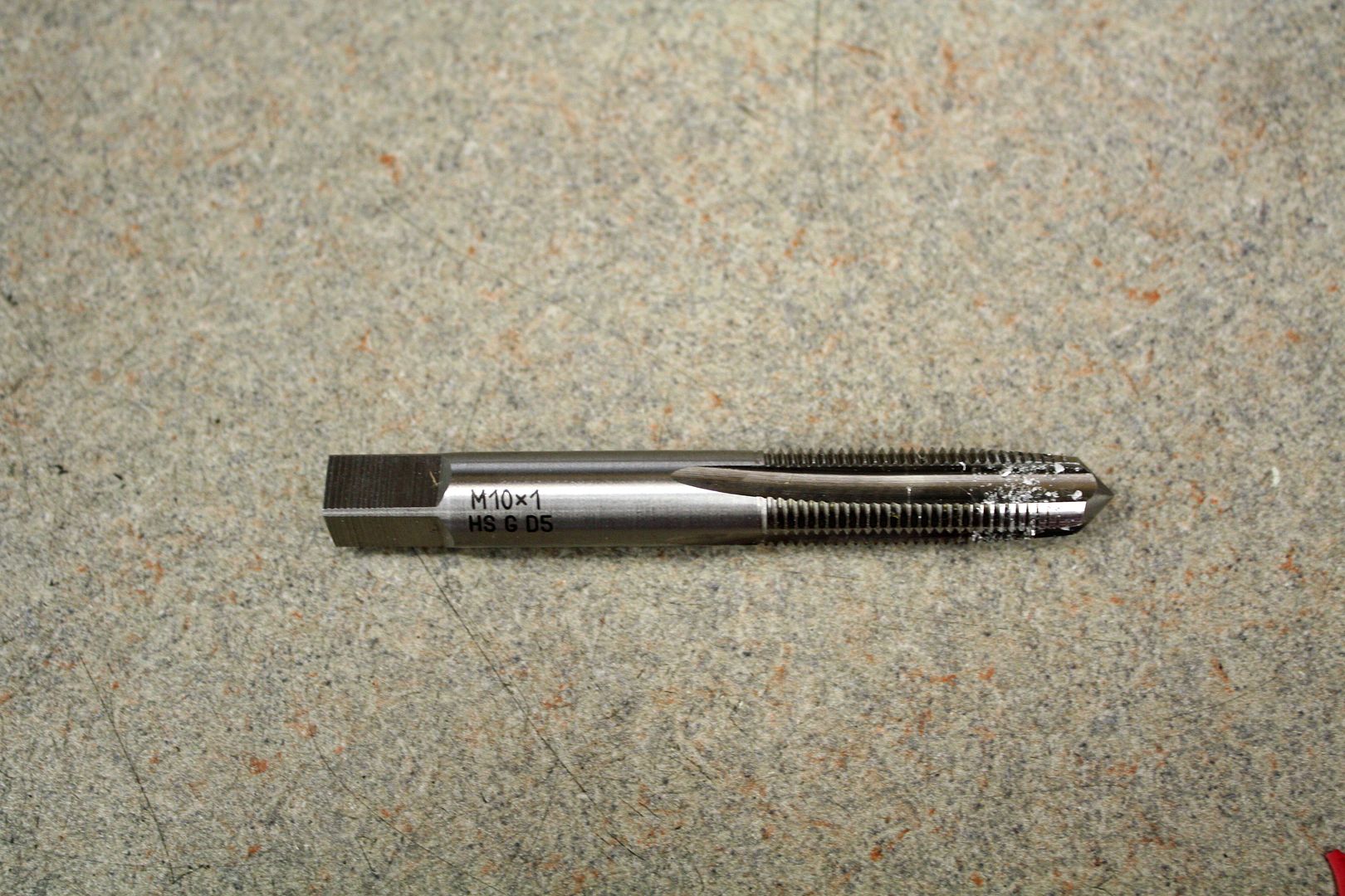
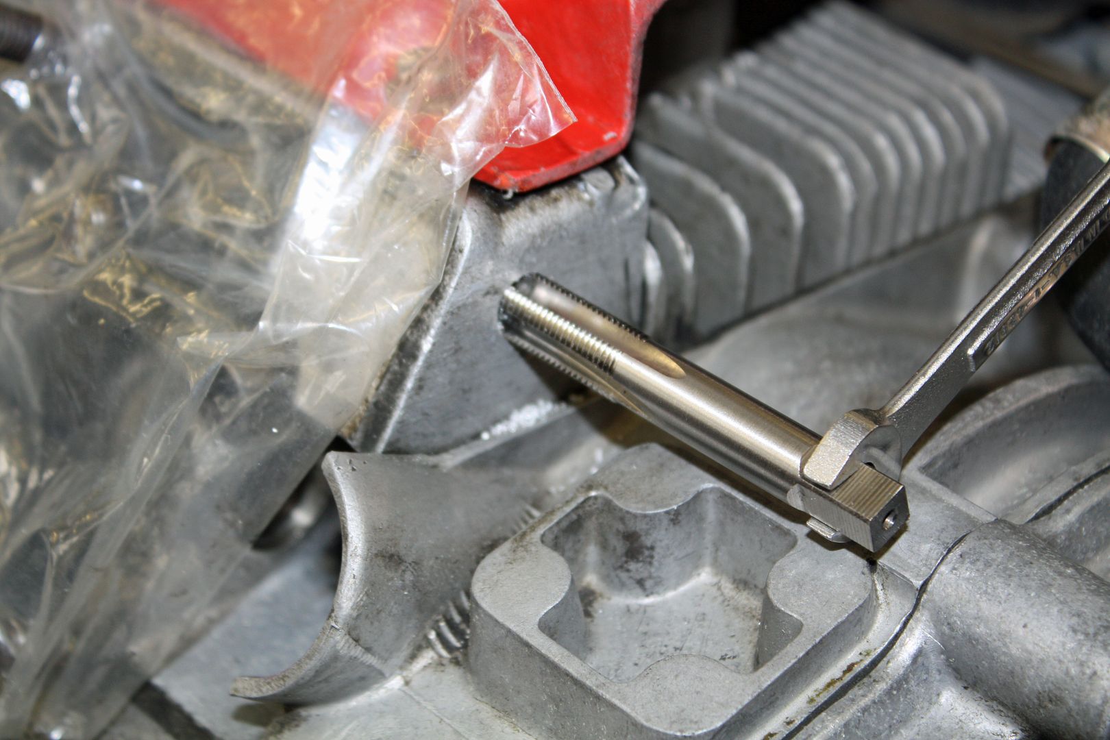
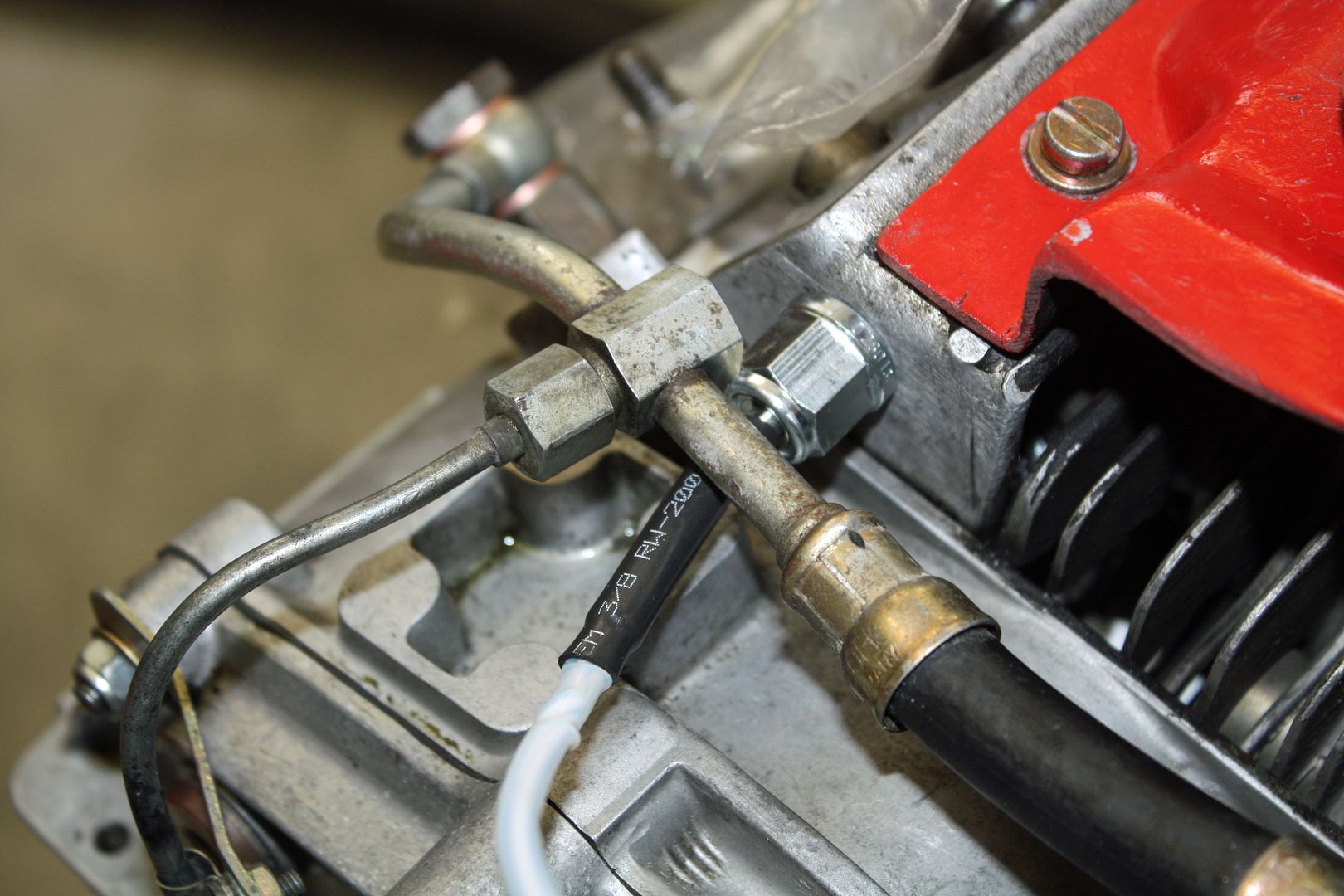
Another day, another sensor for the engine. This time it was a head temperature sensor. It can be installed on either side on the front of the engine. There are two walls in this area and you are to drill only through the first wall. The shavings fall into a void so they will not enter the motor. That hole has to be tapped with a M10-1.0 tap. I have a pretty good selection of taps and dies but this one was not included. After a few calls, I found one at a local bolt and tool store. To get to this area, the chain tensioner pressure feed lines have to be unbolted. I was out of the crush washers for these banjo fittings which meant another trip to find them. I spent a good part of the day driving around!!
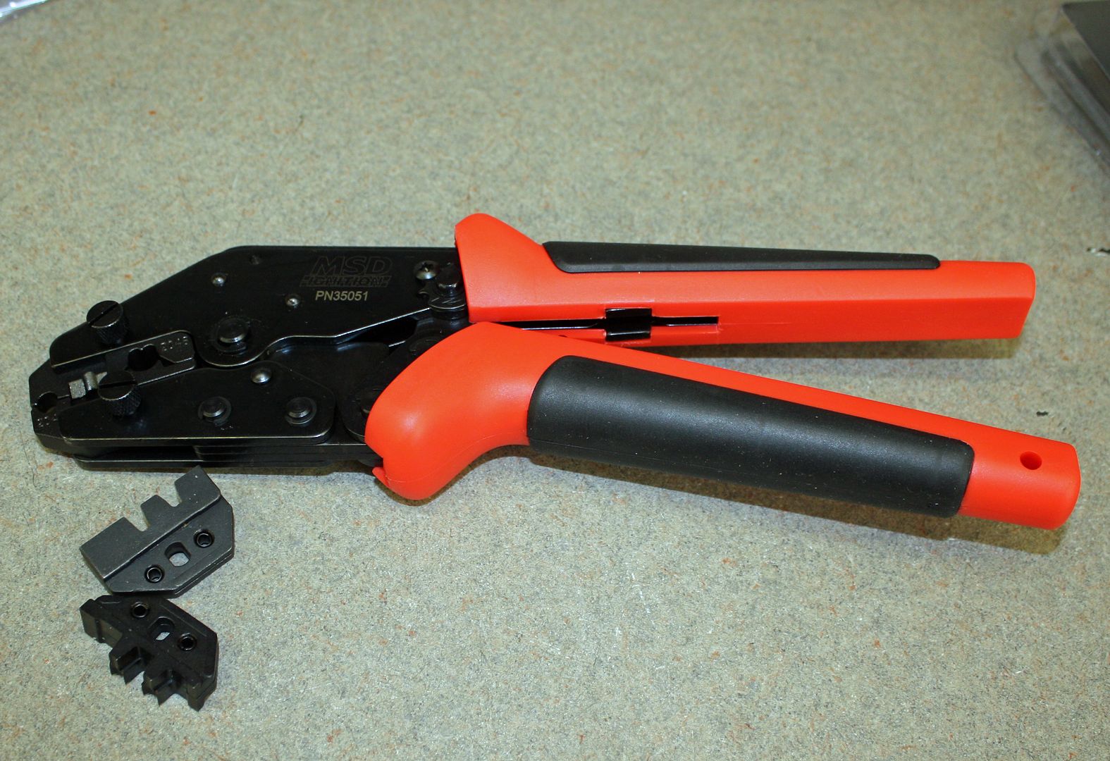
The -6 AN fuel lines and fittings arrived today along with the crimper needed to do the many weather pack connectors required to make the computer happy. My son has an identical crimper but, since he is in the middle of installing the Tesla motor in the '79 911, he will be using his. Normally, I would have borrowed his.
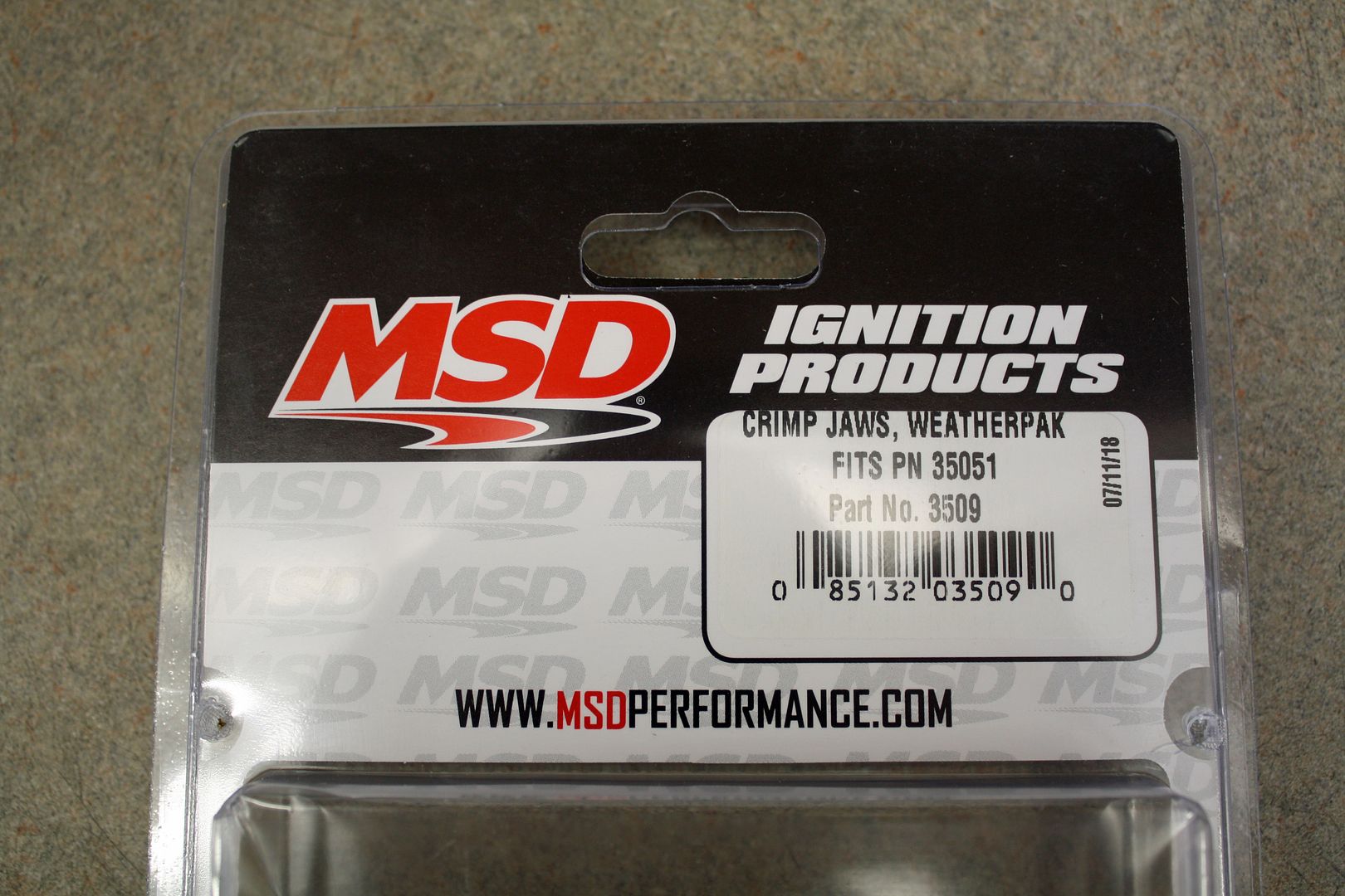


The -6 AN fuel lines and fittings arrived today along with the crimper needed to do the many weather pack connectors required to make the computer happy. My son has an identical crimper but, since he is in the middle of installing the Tesla motor in the '79 911, he will be using his. Normally, I would have borrowed his.


 09-07-2018, 05:30 PM
#42
Racer
Thread Starter
When I retired ten years ago this November, I told my wife that, since she had cleaned the house for the first forty years of our marriage, I would take care of the next forty years. Which is a good deal for me as our chances of being married eighty years are pretty slim!!! So Friday morning is house cleaning day.
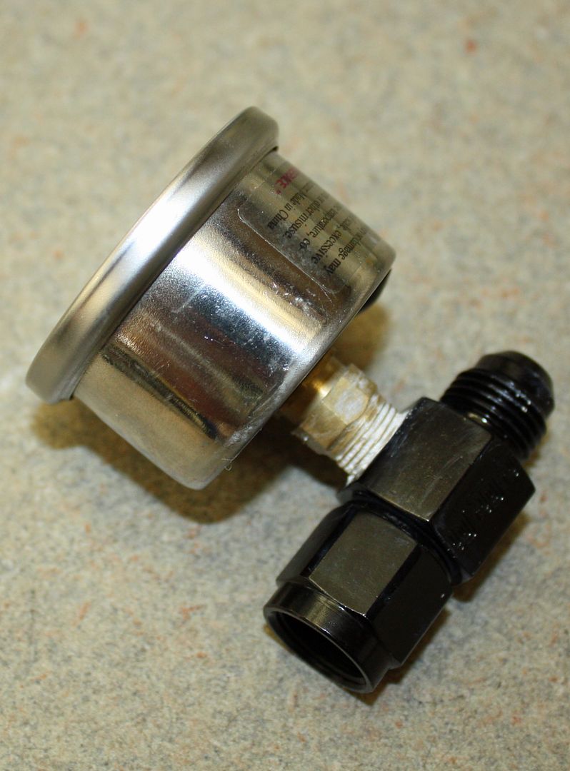
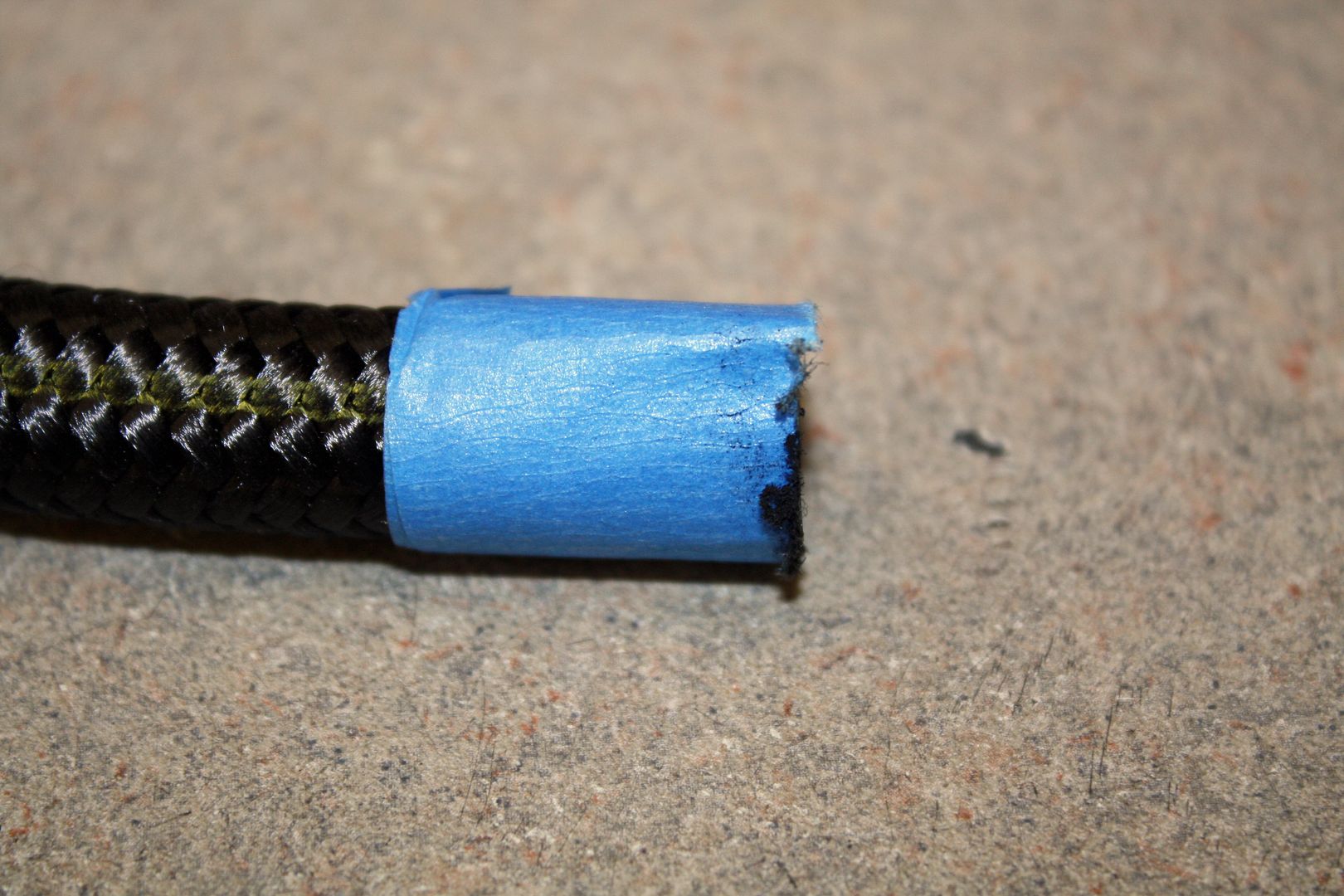
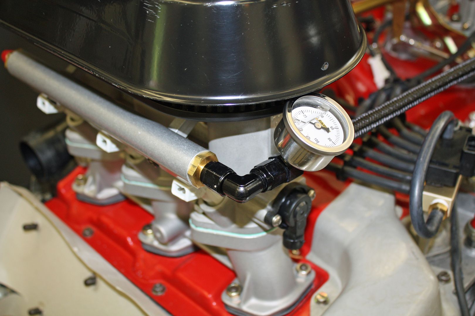
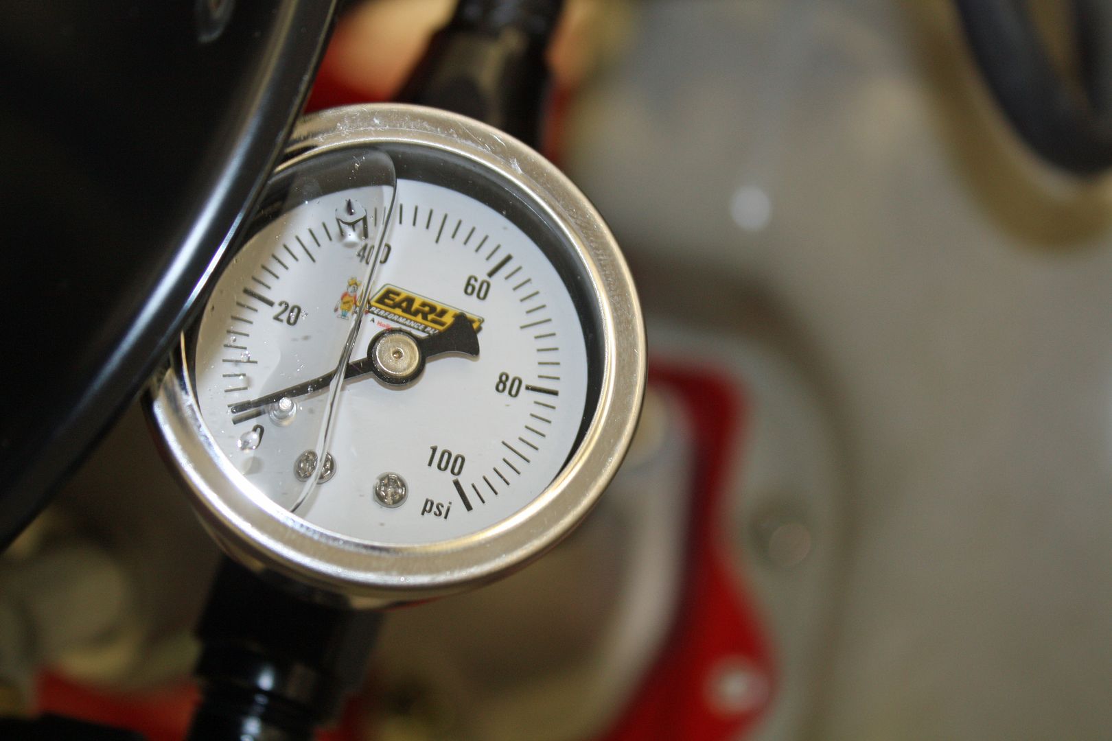
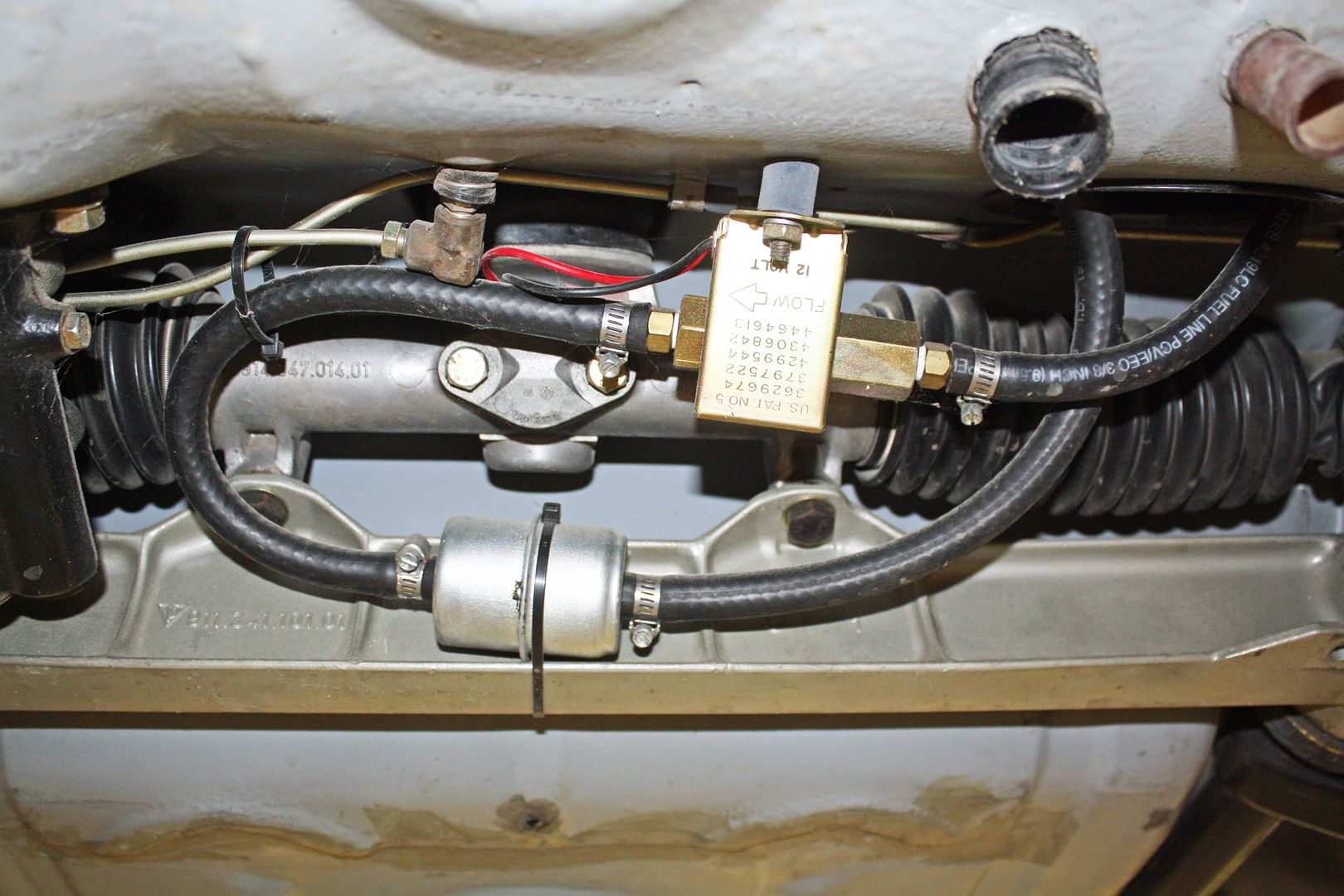
I did spend a very short time on running my first fuel lines. I plumbed in a fuel gauge so I can set the fuel pressure with the regulator. I also ran the line across the rear from carb to carb. My son has lots of experience running AN fuel lines. He told me to heavily wrap the area where I was going to cut a line so the end would not fray. That suggestion worked well.
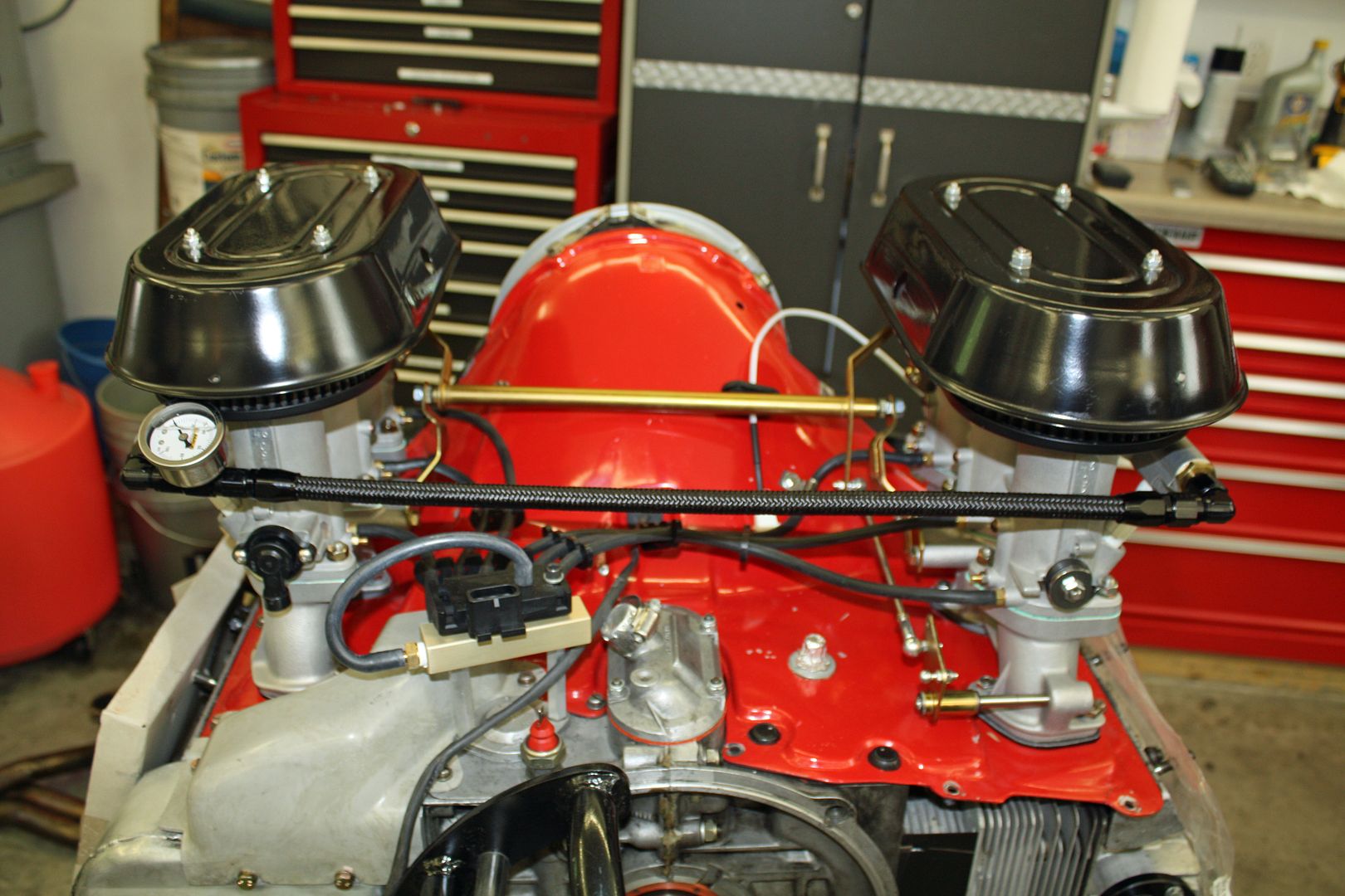
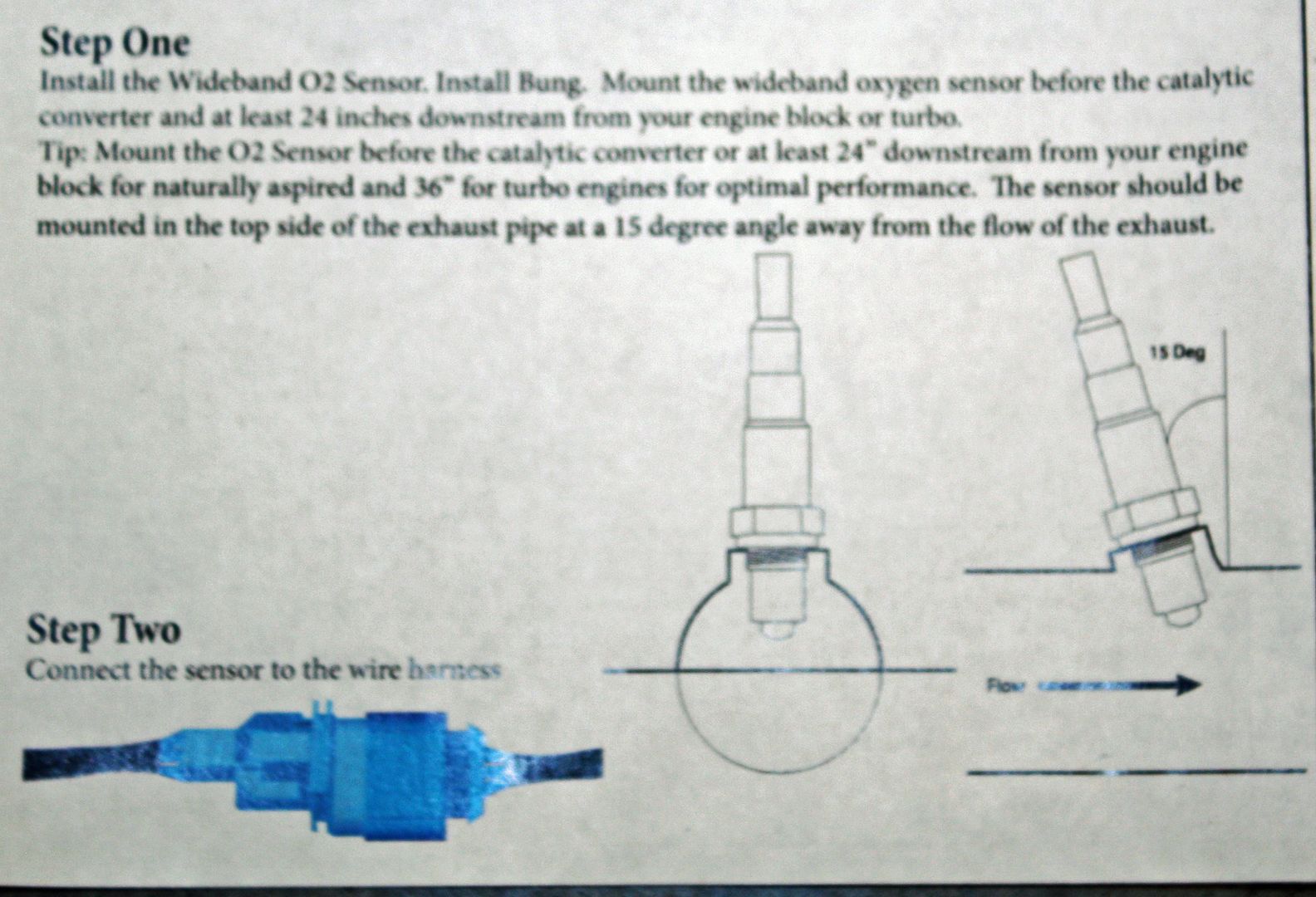
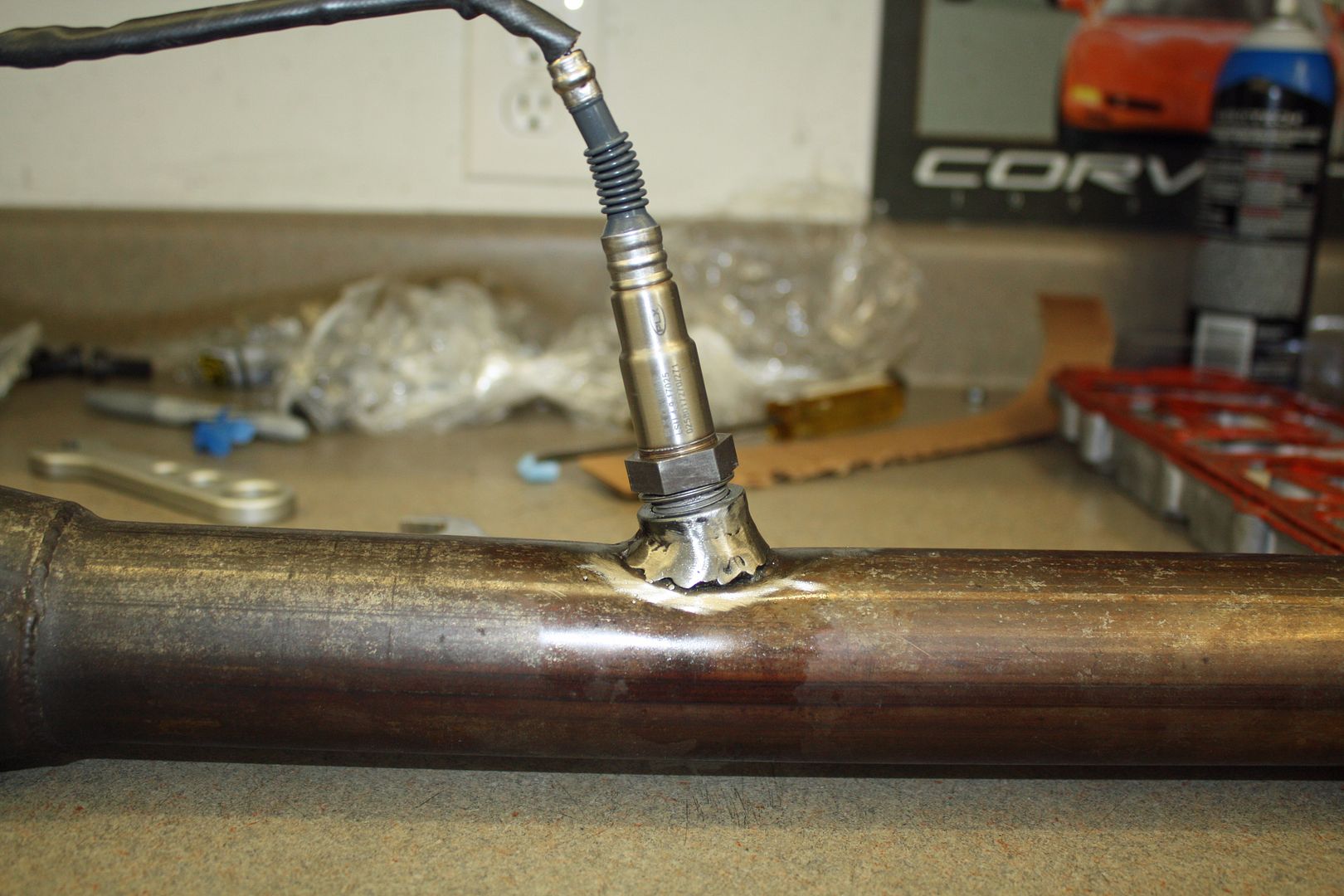
Tomorrow I am taking one of the exhaust's to my son's house to have an O2 sensor bung welded in. The instructions call for mounting the sensor at a 15 degree angle. Should be a good challenge for my son. I will be taking him away from working on his Tesla 911 project. Here are a few pics from last week.
I did spend a very short time on running my first fuel lines. I plumbed in a fuel gauge so I can set the fuel pressure with the regulator. I also ran the line across the rear from carb to carb. My son has lots of experience running AN fuel lines. He told me to heavily wrap the area where I was going to cut a line so the end would not fray. That suggestion worked well.


Tomorrow I am taking one of the exhaust's to my son's house to have an O2 sensor bung welded in. The instructions call for mounting the sensor at a 15 degree angle. Should be a good challenge for my son. I will be taking him away from working on his Tesla 911 project. Here are a few pics from last week.


 09-08-2018, 05:31 PM
#43
Racer
Thread Starter
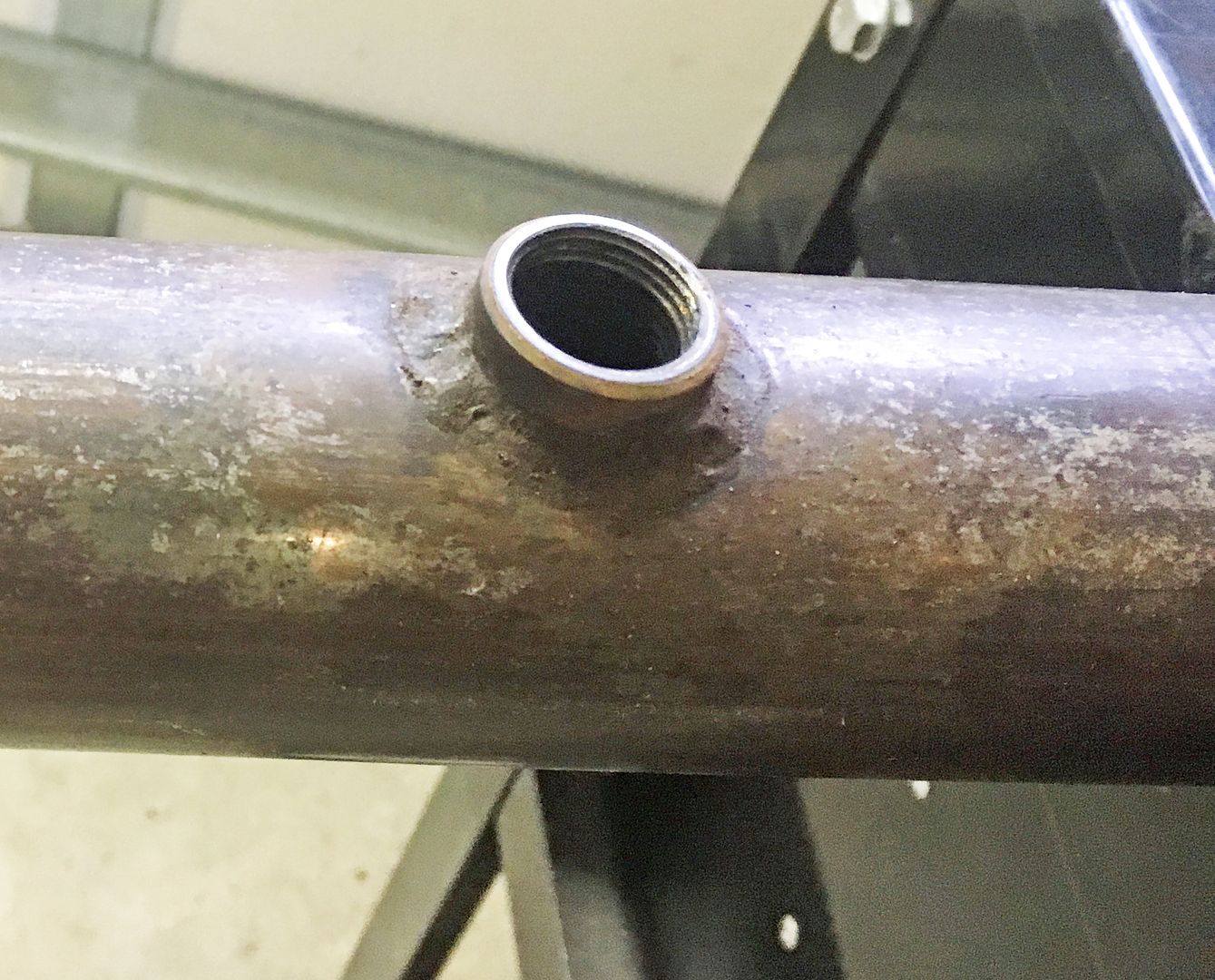
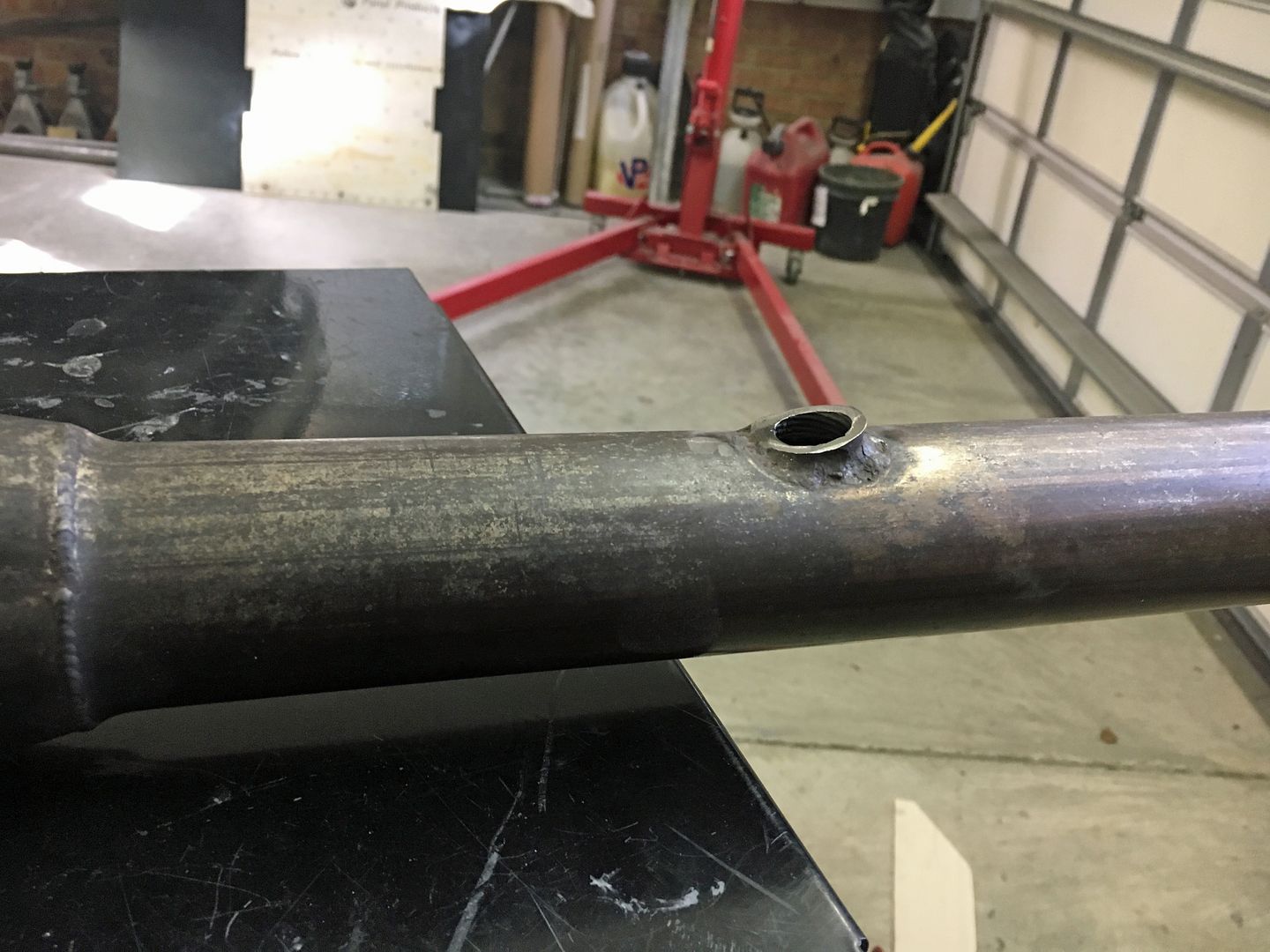
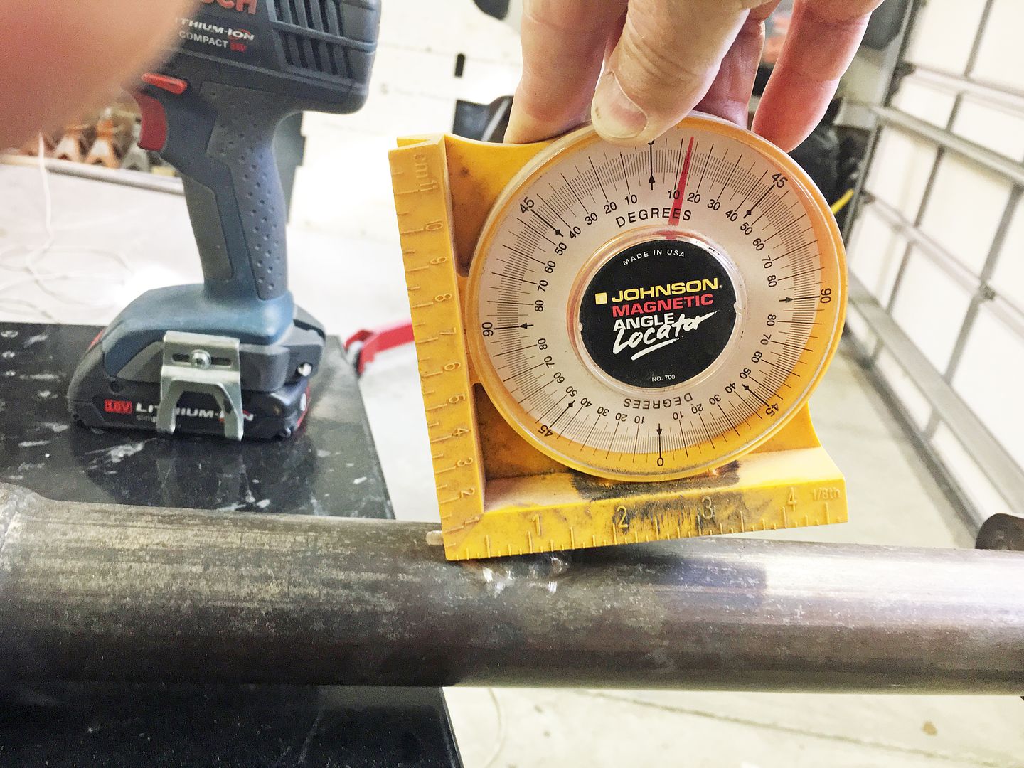
One last sensor!! A wide band O2 sensor had to be installed. The car already had O2 sensors in both exhaust pipes for a gauge on the dash. However, the O2 sensor that came with the kit called for it to be installed at a 15 degree angle. My son had a spare sensor bung so I carted the right side exhaust to his house. He ground down the existing bung to get the correct angle. After test fitting the bung, he decided the bung might be too thick which would not allow the sensor to properly extend into the exhaust. So he put it on a vice and ground it down. Using an angle meter, he fine tuned the bung angle and began welding. Good to have a good son!!!
To fit his wheels to his 911 Tesla project car, Matt had purchased a number of spacers and shims from Elephant Racing. I had mentioned to him that I needed to move the rear wheels out a bit for clearance on the inside. He gave he his spacers and shims. I liked the Elephant spacers better than the H & R spacers that came with my car. I used a 7mm spacer and a 2mm shim to get the clearance I wanted.
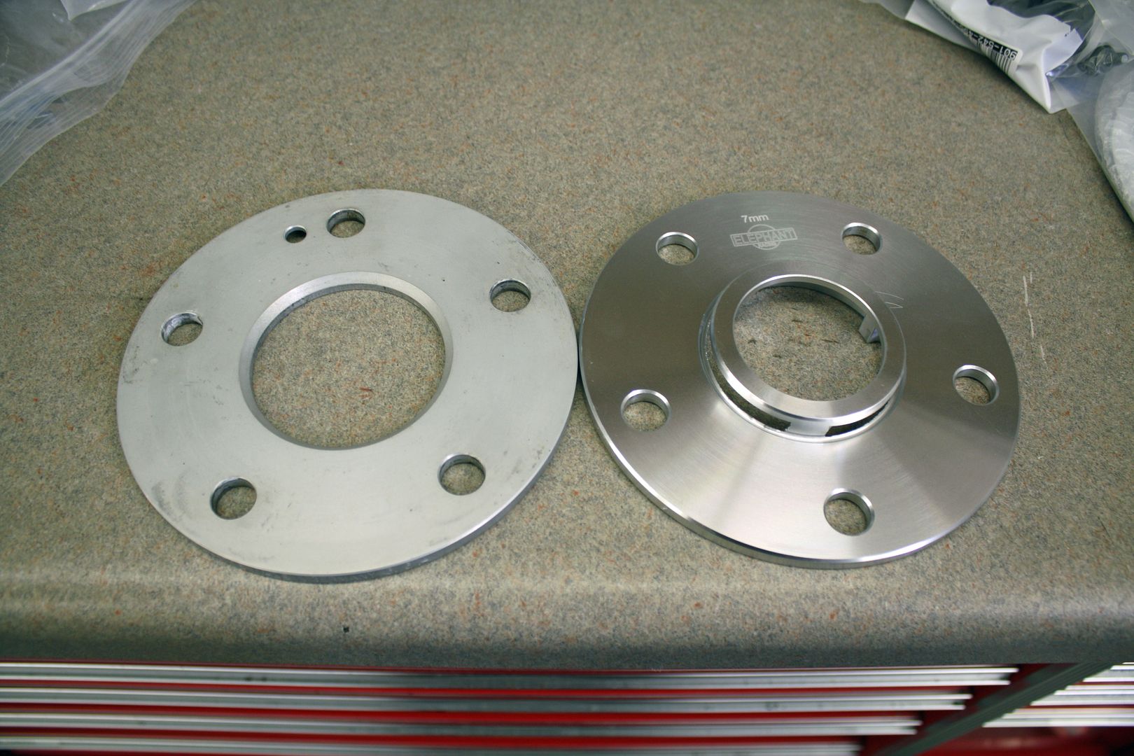
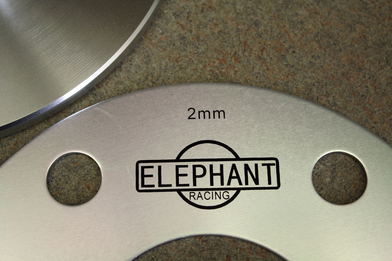


To fit his wheels to his 911 Tesla project car, Matt had purchased a number of spacers and shims from Elephant Racing. I had mentioned to him that I needed to move the rear wheels out a bit for clearance on the inside. He gave he his spacers and shims. I liked the Elephant spacers better than the H & R spacers that came with my car. I used a 7mm spacer and a 2mm shim to get the clearance I wanted.
09-08-2018, 07:17 PM
#44
Racer
Thread Starter
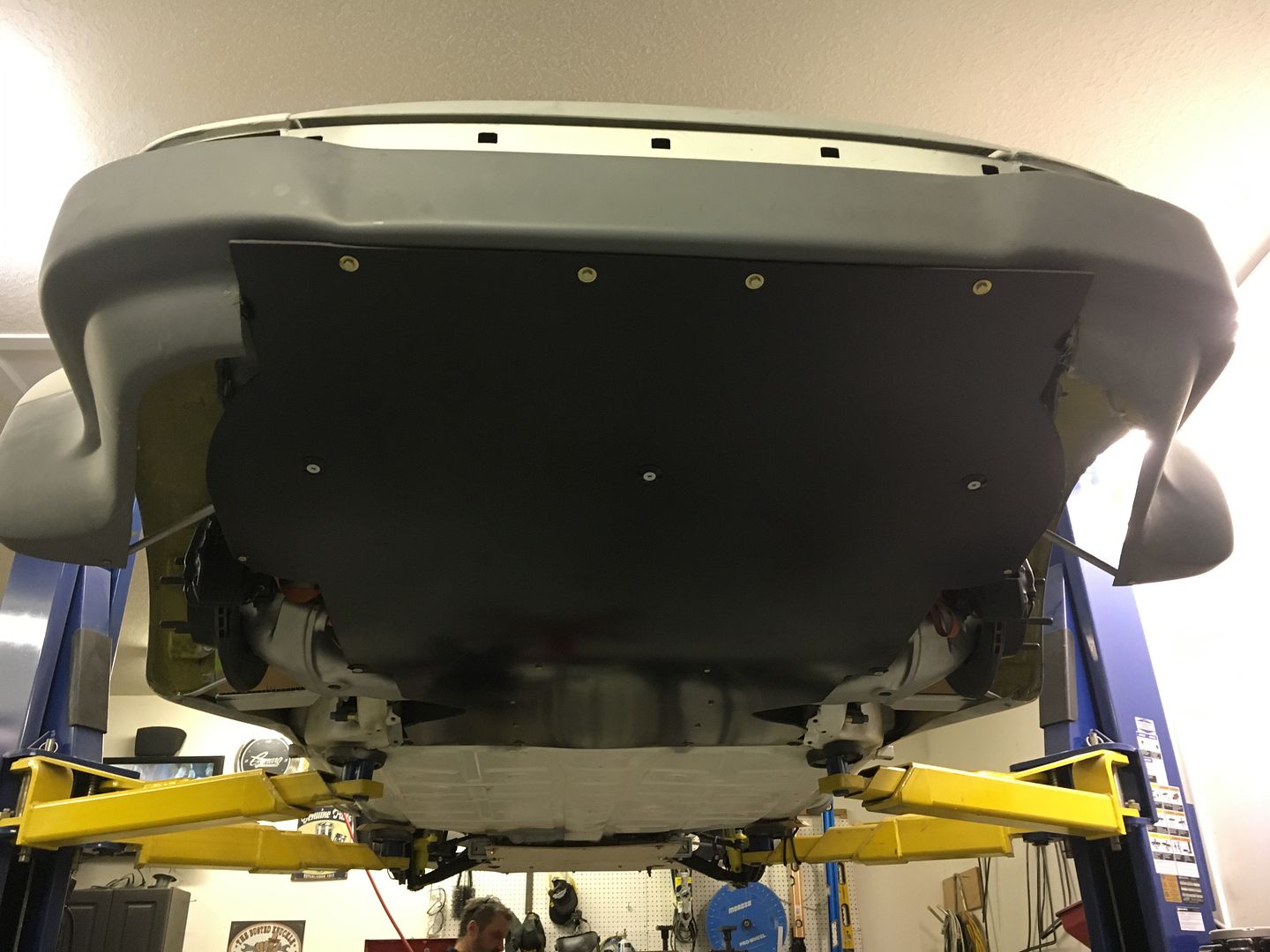
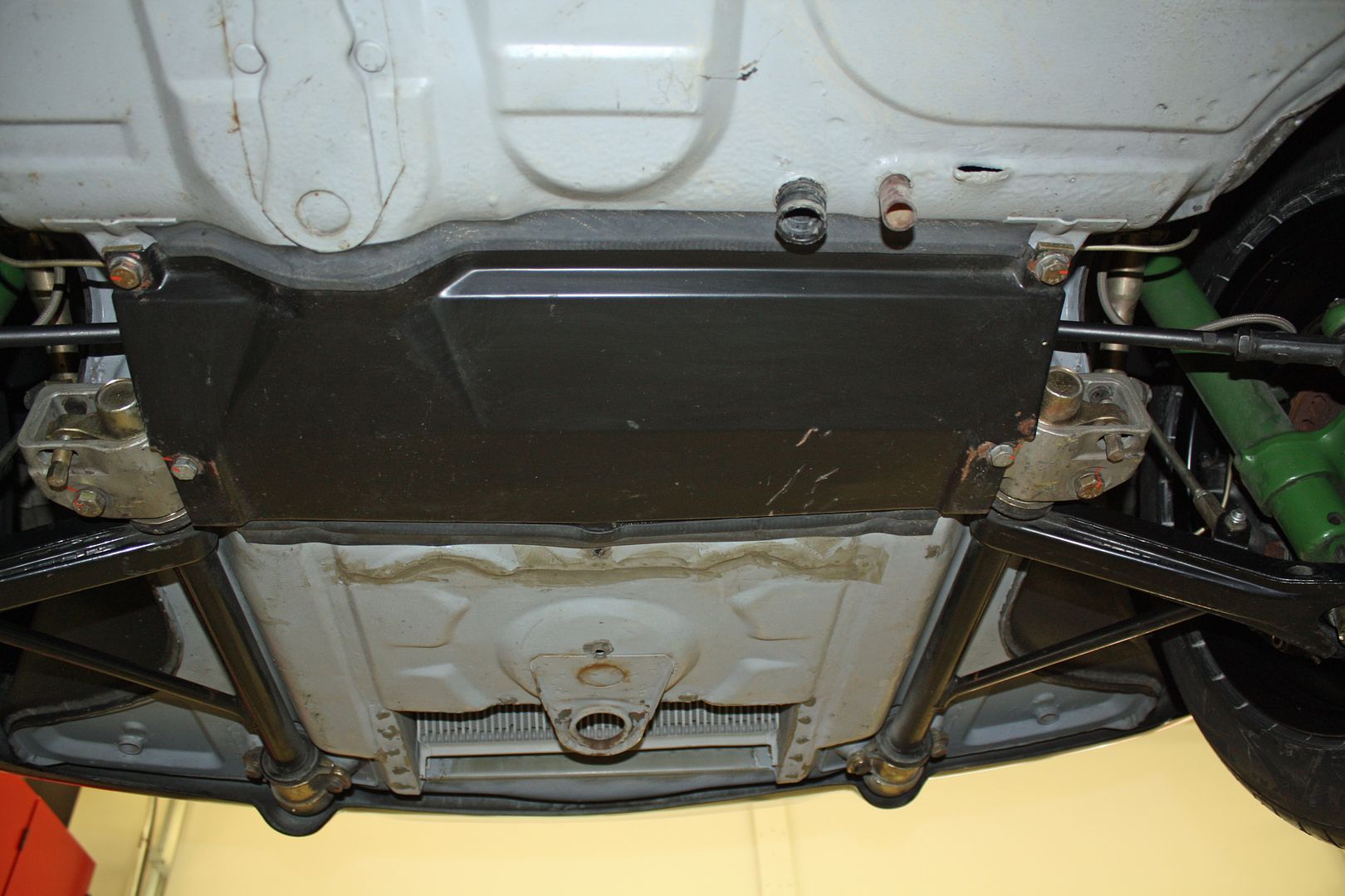
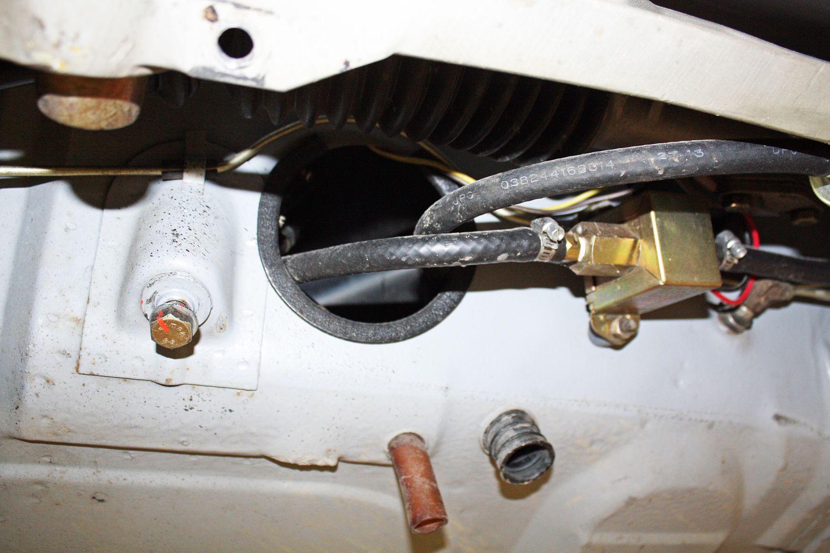
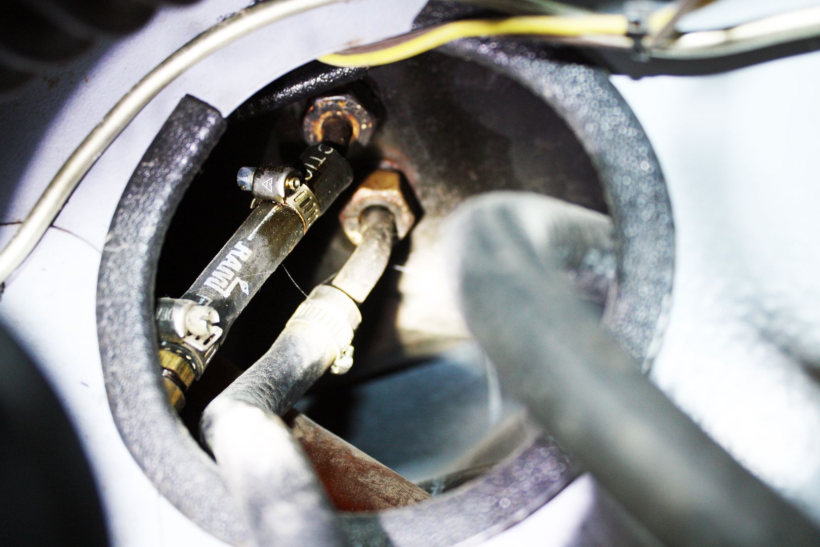
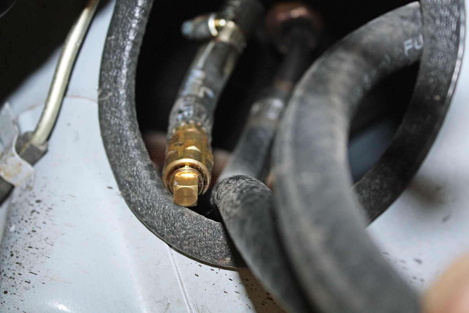
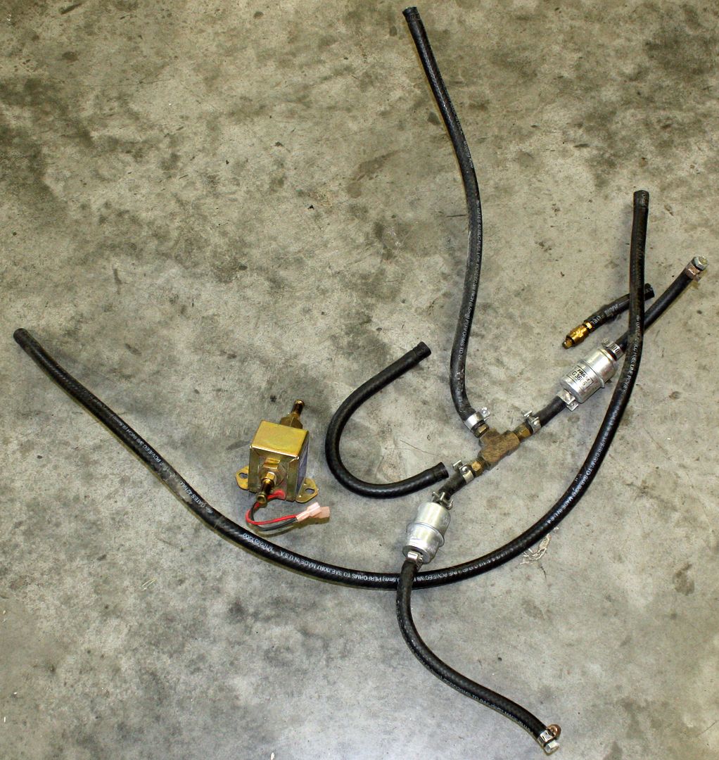
To prepare for running the fuel lines, I removed the front pan to reveal the old fuel pump and lines. Happily, I discovered a fuel return line connector on the tank. After removing all of the old lines at both ends of the car, I can see that I will have to remove the tank to connect the new fuel lines. From what I could see at the rear, it appears there is a metal fuel line that runs in a tunnel from the fuel tank area to the rear of the car. Is that correct? Also, can anyone tell me how the factory ran the return line from the engine bay to the tank?


 09-09-2018, 11:55 AM
#45
Racer
Thread Starter
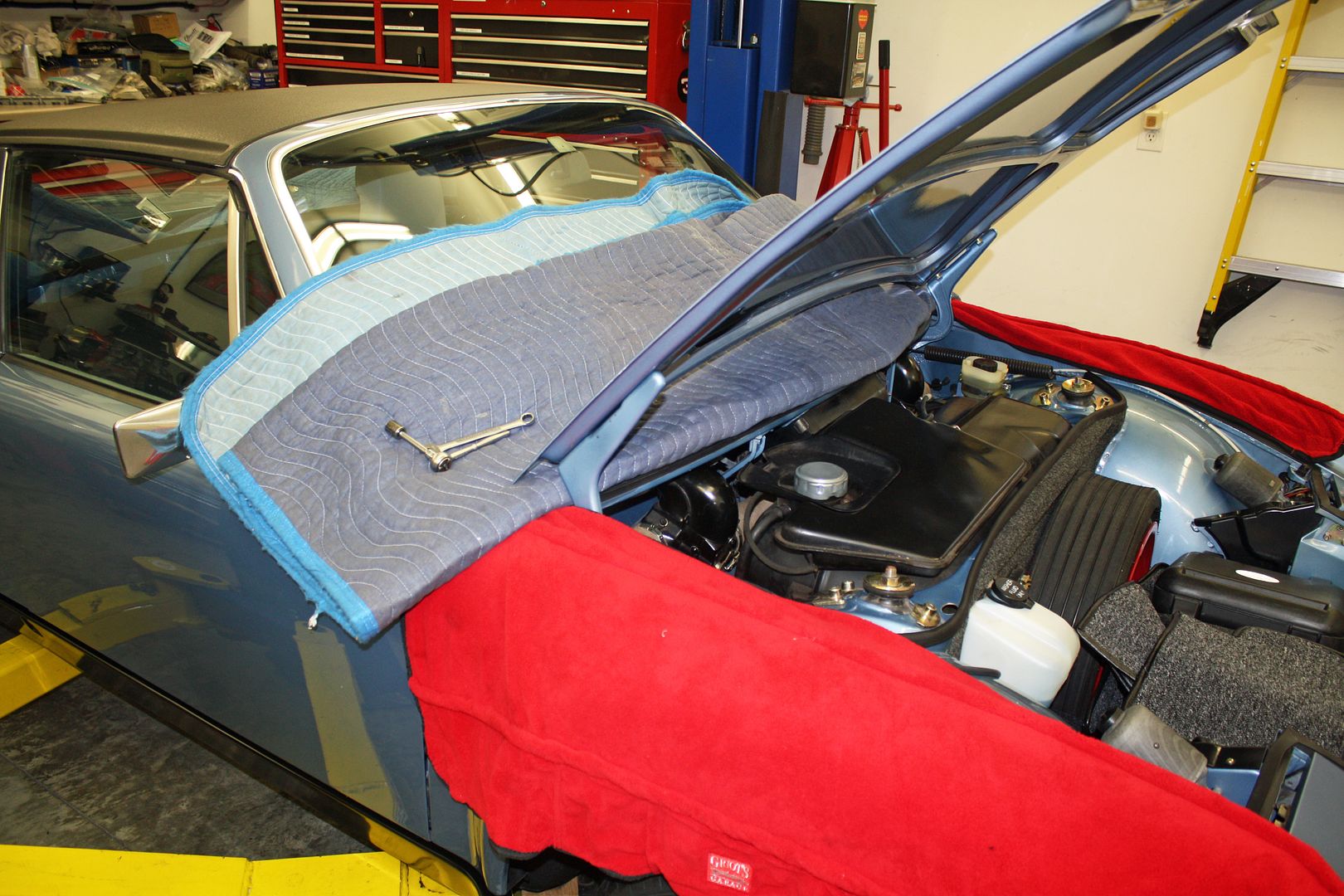
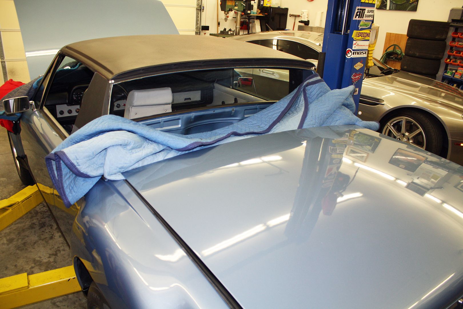
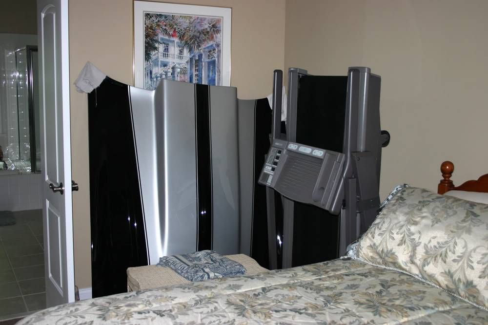
My buddy came down this morning to help me remove both hoods. They ended up in my wife's bedroom.
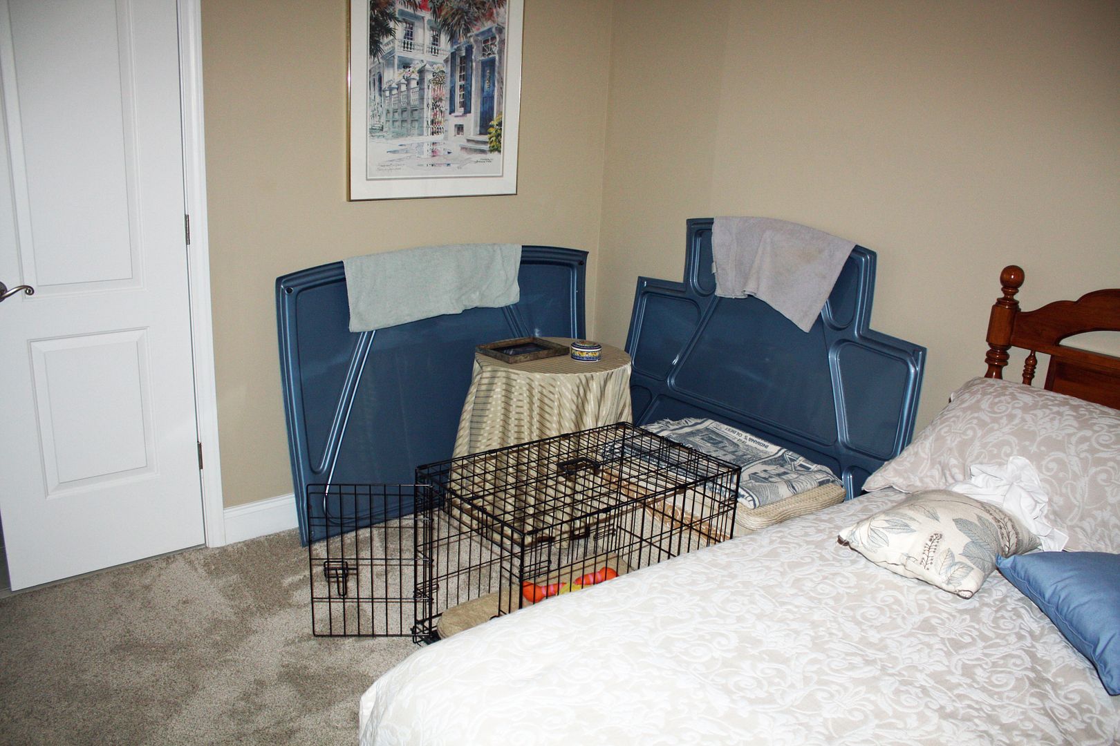
The wife's bedroom have been the repository for a number of hoods from project cars over the years.
1964 Corvette hood
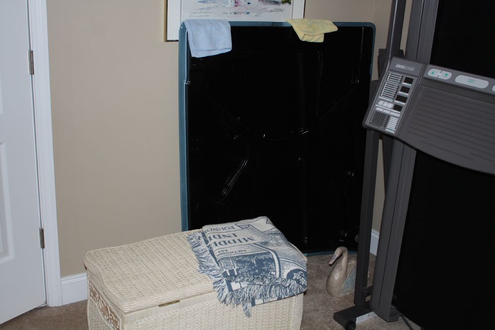
1977 Camaro Pro Touring car


The wife's bedroom have been the repository for a number of hoods from project cars over the years.
1964 Corvette hood

1977 Camaro Pro Touring car
