When you click on links to various merchants on this site and make a purchase, this can result in this site earning a commission. Affiliate programs and affiliations include, but are not limited to, the eBay Partner Network.
So I popped a beer yesterday afternoon in the garage as I continued to prep my CPR/WUR for rebuilding. One of the steps is to simply resurface the mating surfaces for new gaskets or for sealing purposes. This involved simply moving the part around on wet 1000 grit sandpaper.
Since my engine is a US delivered lambda using system, my fuel management system is expecting the CPR to provide 3.4 - 3.8 bar when fully warm. Warm engine performance is obviously very important therefore, i think I shall set my ROW CPR number 089 for 090 US lambda system pressures. Yes, the pressure graphs do overlap somewhat and there is room for some margin on error, might as well give the fuel distribution unit the pressure it is expecting.
Comparing the graphs, it looks like at 10C, the 089's range is 1.0-1.4 bar. The 090 is 1.35-1.8 bar.
At 40C, the 089 range is 2.8-3.25 bar and the 090 is 3.35 - 3.8 bar.
Looks close enough to me that how the units warm up and their change in pressure is close enough that if I set the 089 at middle of the range for 0.90 (if I can be that accurate), that the in-between range will work for what the fuel management system is expecting.
My unknown is the affect of vacuum on the 089 vs no vacuum connected on the 090. I realize, the warm pressure needs to be set with normal idle vacuum such as 16".
> My unknown is the affect of vacuum on the 089 vs no vacuum connected on the 090.
Apply a small vacuum on the port and you can see the affect on fuel pressure. It is doing nothing more than moving a plate against a spring up/down. Fun stuff.
But going back to the problem as described in your first post, I still suggest checking for vacuum leaks first.
I would start with the toilet seat aka "pop off" valve.
Thank you. I pulled the large o-ring out of the seal of the pop off. Looked rather round most of the way around. I did flip it over. Anyone know the size to order new ones?
I did use my vacuum pump to pull a vacuum on various lines where I could. I visually inspected the intake manifold tube rubber pieces where I could and they are snug and not cracked - can't hardly see the right hand side ones. Again, I hope they're in good shape as they were replaced 1.5 years ago when the engine was rebuilt.
Anybody use a smoke machine to test vacuum seals? If so, where to push the smoke into the system?
So I’ve been thinking a lot and studying the O2 Sensor CIS fuel system.
My 81 was parked for a long period, 11-12 years or so......why? My experience is that cars get parked for long periods usually because something is wrong and the owner doesn’t want to chase the problem.
Why was the Control Pressure Regulator (CPR) changed to a Euro 089 vacuum controlled device from the 090 US CPR?
Why was the Oxygen Sensor Relay removed?
Maybe the O2 system wasn’t working quite right so a mechanic swapped in the Euro CPR and disconnected the 02 system to run this way instead?
How does the Frequency Valve behave with no power?
How well does the Euro CPR interact with the US O2 system Fuel Distribution Unit?
As a reminder, I started chasing this problem because the engine had no power until fully warm. Secondarily, it seemed to me that full throttle was rather underwhelming, but I haven’t driven another SC since 1982 so nothing to compare.
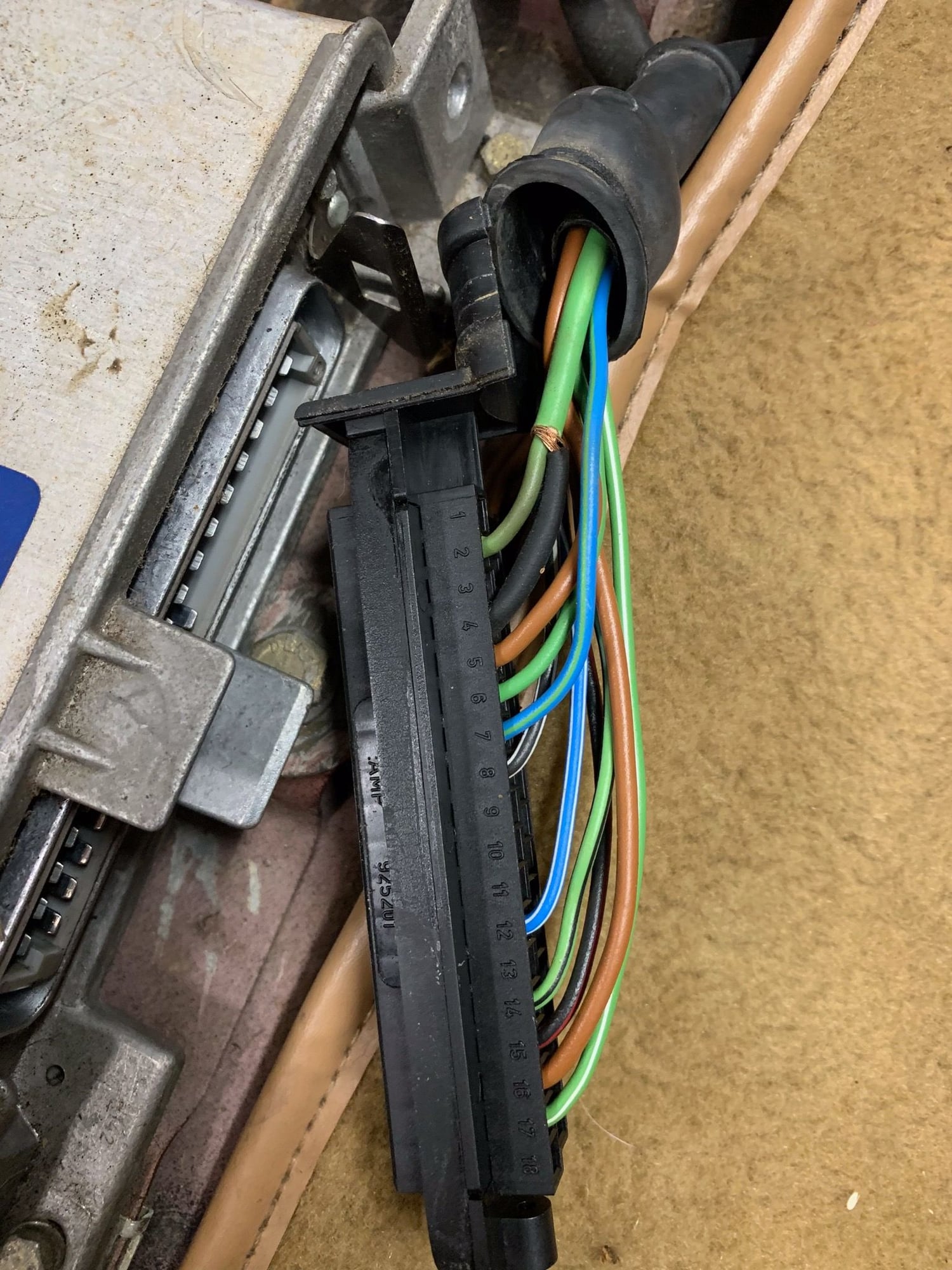
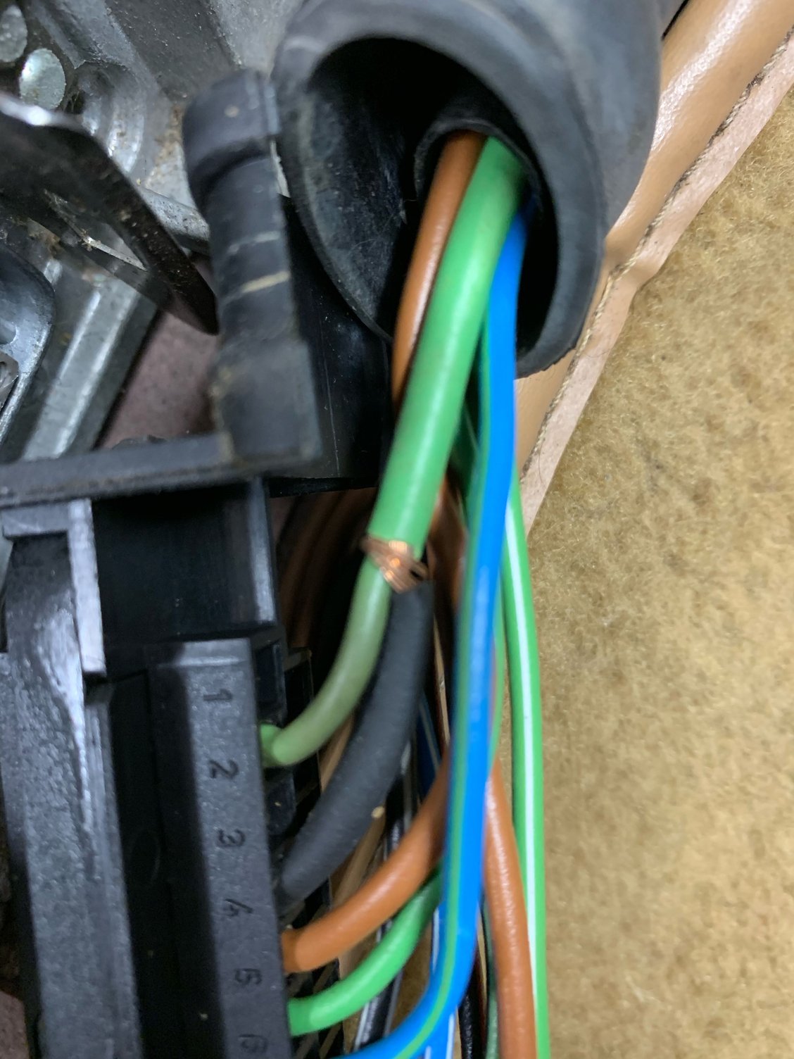
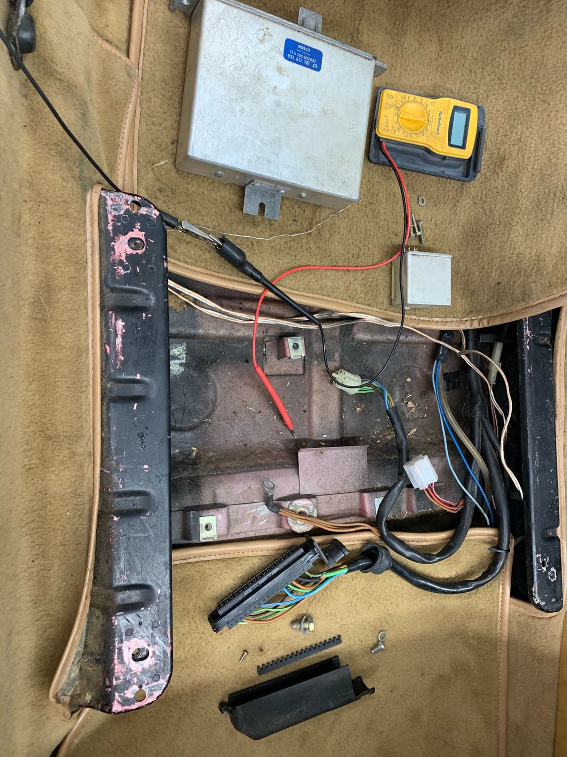
Today I started chasing wires. First, I removed the passenger seat. I started with the plug for the O2 sensor relay. I unplugged the enrichment device and the ECU for their plug’s access. (My first thought when pulling back the cover of the ECU plug to see the wires was what I thought was a crappy attempt to solice into the neighbor wire, but I see NCA on the diagram which means the wire is shielded for interference so what I see is the jacket aand the jack plugs itno the ECU. Look for photo below.)
O2 Relay: Red to fuse 18, yes, continuity. Red/white to 30 terminal on fuel pump relay. Also red/white to CPR. Brown ground. Black/white to 15 ECU. Black/red to enrich device plug and to Frequency Valve....Whoa! No continuity to Frequency valve. Problem 1.
Next, started chasing wires from Enrichment Device. Didn’t take long to find no continuity on the green wire between enrichment device and the 15 degree throttle switch. Problem 2.
Then I started chasing wires from the ECU plug which aren’t connected to the O2 Relay or the Enrichment Device.
I removed the heater blower motor on the left side of the engine for better wiring access. But, I can’t seem to get to the 35C Temp Switch wire end, device located at rear of engine (far back). And I can’t pull the harness loose from the Aux Air Reg on the right hand side due to lack of access. So more work to do tomorrow.
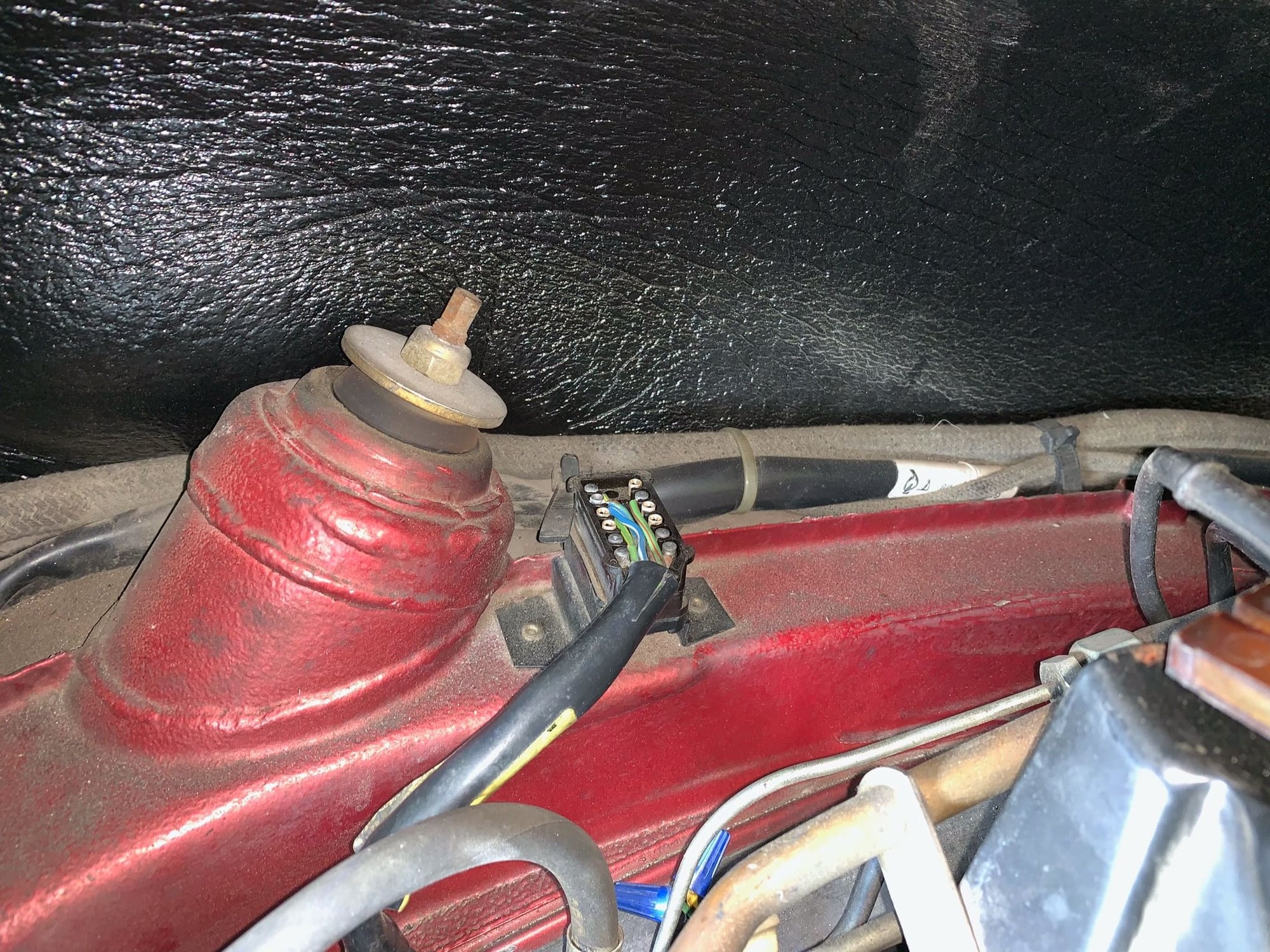
Regarding the two known problems, I saw the harness plug on the body extreme forward engine compartment, left center, and pulled it loose. The cap pops off easy and I studied the wire connections and their coordinating female plug ends on the socket on the body. I traced those wires back to their coordinated wires in the passenger area. Ah ha! The black/red wire to the enrichment device has continuity there, good sign. And the green throttle 15 degree switch does too. I examined the male end connectors of the plug and they look just fine - no corrosion. But I rubbed on them with a cloth nonetheless. I pushed the plug back into the harness and both problem wires now have continuity through to their parts. Congratulations to me.
Really tired so I opened an IPA sat down to think some more. Tomorrow I’ll try to finish tracing what I didn’t get to today.
A few photos for you:
ECU plug uncovered
Wire 2 is to O2 sensor. Wire 4 is wire 2’s shielding jacket.
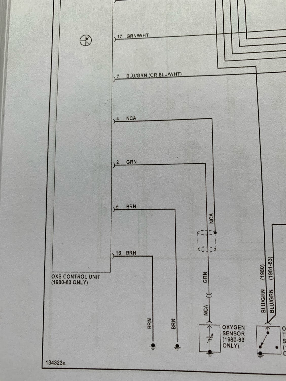
Wiring diagram showing shieldin NCA wire.
Bright White plug is the O2 Relay plug. Round white plug is for Enrichment Device. Black long plug is for ECU
Harness connection plug, left forward area of engine compartment. See twist caps below? I hate that - unacceptable workmanship. More to investigate.
I have continued verifying wiring harness connections and testing components of the CIS system.
I was able to pull the wire off the oil temperature sensor located back center of engine. Continuity checked out and I was able to test and verify the temperature switch was open, which it should be below 35C.
Funny: I was struggling with my little 2” mirror on a handle. I needed a larger mirror to see a larger view behind the intake. Well, I borrowed my wife’s makeup mirror from her dressing table. Yesterday morning I recieved a text asking where her mirror had been moved to. I told her it was in the garage, in the front of the engine compartment of the 911. She wasn’t amused.
I was testing the micro switch for the throttle position, the one which is supposed to open at 15 degrees movement. Clearly mone was opening about 2-3 degrees. So I used a protractor, measured the throttle arm to have some point of reference, which measured 2.875”. On a rough estimate, the throttle arm tip end should move about 3/4” to rotate the throttle shaft 15 degrees. There isn’t enough adjustment on the bracket to give my switch 3/4” free movement befor the switch closes, so I reshaped the switch arm to max out what I can. It closes about 5/8” or about 12 degrees.
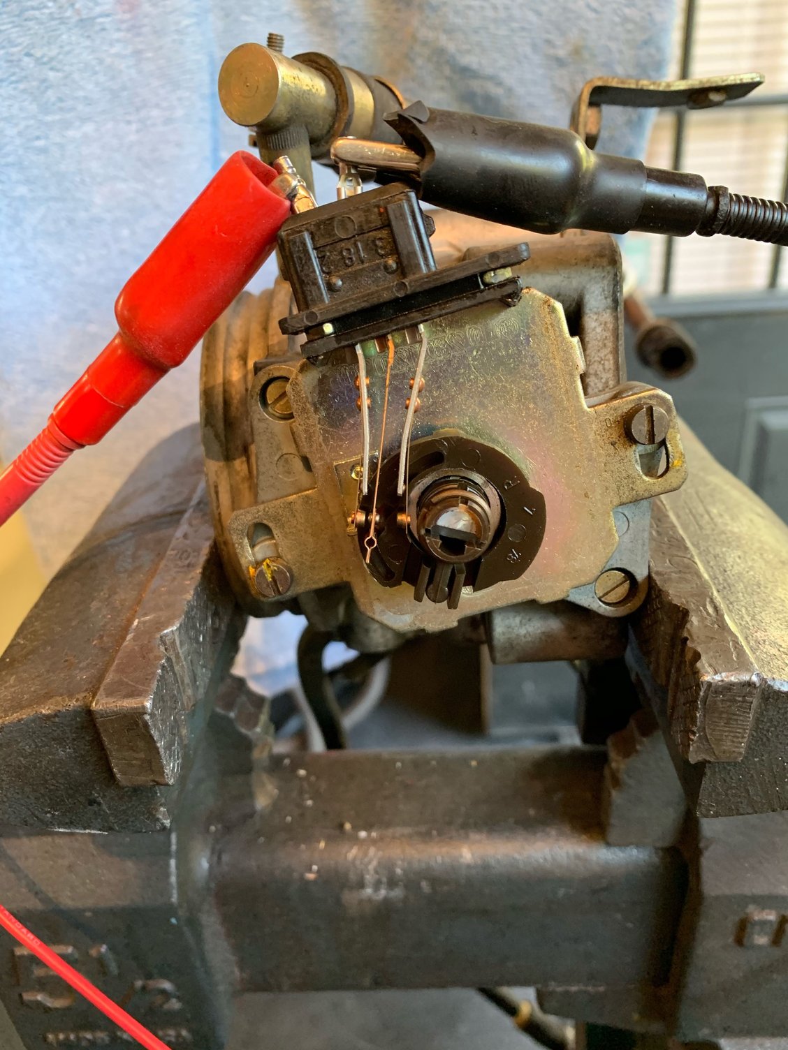
Next I wanted to check the other throttle switch settings. There are three contacts on the device, labeled 2, 18, 3 from top to bottom.
2-18 closed at idle, opens at about 2-3 degrees. 3-18 close at about 35 degrees and stay closed all the way to WOT.
Mine wasn’t right and I couldn’t get to the lower flat head screw to loosen the device to rotate and adjust.
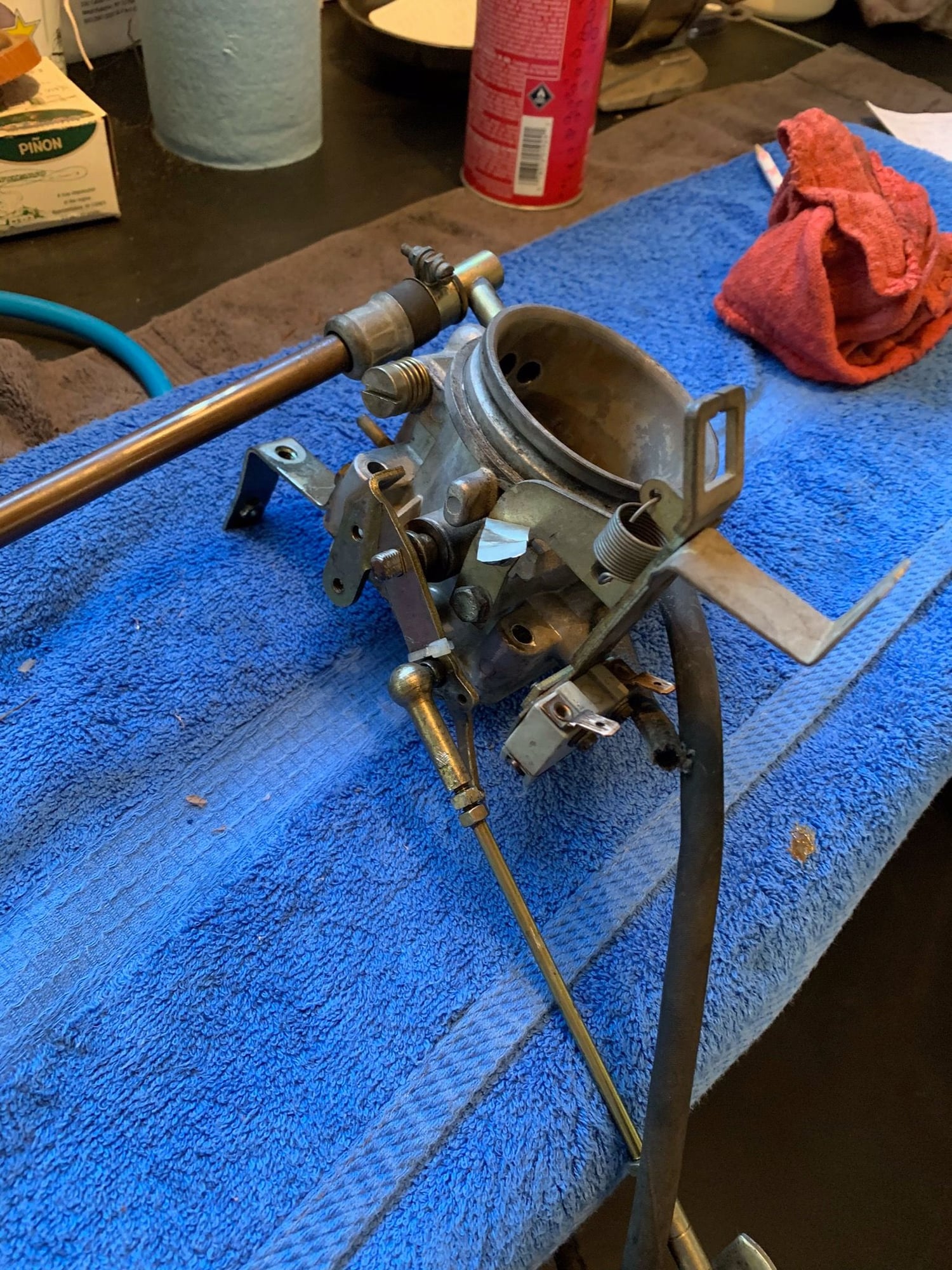
So I removed the throttle assembly. I couldn’t get the 2-18 contacts to open any time sooner than about 14-15 degrees. I popped the cover off the device and see there are two arms with the contact points. I carefully bent the 2 contact arm out a little so it would open sooner. A little trial and error and using a measure to see how far the throttle arm tip end moved, I finally achieved 2-18 opening about 2-3 degrees, which is about 3/16” tip end movement.
Then I worked on 3-18 closing at 35 degrees which is about 1.75” of tip end movement.
Note: i had my wife, while in the driver’s seat, press the accelerator pedal to the floor. I noticed the butterfly valve wasn’t near fully open. It looked like about 2/3 open. I had two driving complaints, one, it ran poorly when cold, two it was underwhelming at WOT. This is definitely a cause of number two. I’ll adjust linkage.
I worked on the Aux Air Reg. I used a mirror so I could see inside the device and visually watch the device close as it warmed up. I put 12v to it and after about a minute, I saw the door start to slide shut. After 90 seconds, there was only a small slit left, clearly enough for air to go through. It didn’t move any further, but this device gets somewhat heat warm up too.? I sprayed a kind of penetrating oil which leaves an oil film, on the door hopefully to allow it to move more freely. (My engine did not idle high)
So I believe I’m ready for assembly of everything. My 15C oil temp sensor circuit was open with the temp at 66F ( should be closed below 59F/15C). My frquency valve measured 2.5ohms (should be 2-3). All my harness is in good shape. I’ll replace several suspicious vacuum lines and the throttle assembly O-ring. I did purchase a smoke generating device which I hope to use very soon. I’ll post results when I do.
Still waiting on the rebuild kit for the CPR/WUR, grr two weeks.
Throttle assmbly on bench The throttle switch exposed. Left arm is 2, middle 18, right is 3.
Last edited by thinkiwanta928; 04-03-2019 at 08:34 AM.
Reason: Forgot to mention
Seems like you're chasing your tail with all these complicated tests when it could wind up being nothing more than the more common cracked air box syndrome, considering the symptoms you describe.
Seems like you're chasing your tail with all these complicated tests when it could wind up being nothing more than the more common cracked air box syndrome, considering the symptoms you describe.
Cheers,
Joe
Let's review:
First, I discovered the CPR/WUR was not providing the proper fuel pressure when cold
Next, I found there was no O2 Sensor relay installed, therefore the entire ECU system was disabled
Third, I discovered no continuity for the green wire between the 15 degree throttle switch and the O2 Sensor relay
Fourth, No continuity on the black/red wire between the fuel frequency valve and the O2 relay nor the ECU
Fifth, A couple of vacuum hoses are cracked and one broke in my hand as I pushed it aside
Sixth, The throttle linkage was not opening the butterfly a full 90, it wasn't even close, maybe 2/3 opening (think of the fun missed out with not being able to give the engine full throttle)
Seventh, the 15 degree throttle micro switch was opening way too soon
Eighth, The just off idle, 2-3 degree micro switch was staying closed until about 15 degrees
Ninth, The 35 degrees to WOT micro switch wasn't closing until about 45 degrees
All of these issues have been corrected while waiting for my CPR/WUR rebuild kit. All of these issues can affect how the engine performs. These are not complicated tests but the simple verification of the robustness of my current car's system. Once i start it back up, all of these things are already checked off the list of possible problems. One easy thing to change which I have not verified because the engine needs to be running is the oxygen sensor itself.
Currently also waiting on a new o-ring to seal the throttle body to the intake box. Should arrive tomorrow. I'll install it and some new vacuum hoses and then fire up my smoke vacuum tester to search for air leaks such as fuel injection o-rings, various hoses, the sealing o-ring of the pop-off valve, and intake system leaks. I'll post my findings.
Still waiting on a kangaroo to come hopping down my street to hand me the Australian ordered rebuild kit for the CPR/WUR.
I received the throttle body o-ring to seal to intake so it is now installed. All vacuum hoses are back in place and their according clamp cinched up.
So I fired up my newly aquired smoke machine. Really slick and within about 30 seconds started pushing smoke out the tube end. I connected it to the vacuum hose which goes to the electrically controlled vacuum regulator for the distributor retard (I think). I used a weight to hold the throttle open so smoke could easily get above the butterfly. Not too long afterwards I see smoke seaping around the air flow sensor plate so I know smoke is working its way around. I lifted the pop-off valve and was pleased to see a thick wafting of smoke release through the hatch opening.
I carefully studied hoses all over, examined the intake tubes you can see and the area otherwise, intake seals around the injectors, etc.
I did not see smoke anywhere, not under the engine, not on top, not in the car near the gas pedal (Is that the vacuum line above and forward that goes to the brake booster? There’s a steel line that changes to rubber hose.). And no smoke around the booster.
Whew! Finally received my CPR or WUR rebuild kit. Followed instructions very closely to rebuild the unit. Had a slight vacuum leak and the kit instructions imply the rivet pins are the common leak source so I gave them another firm tap each and that solved my vacuum leak. Setting the pressures per the instructions is rather interesting. With the device on the engine, one sets the fuel pressure gauge in place for normal testing. Then one taps in the fuel cell plug, to get the proper reading for their year's configuration. With or without vacuum. Then have to tap in the bottom plug for more setting. Finally, with the engine cold and knowing the ambient temperature, the cold running fuel plug is tapped down to reduce the fuel pressure to the proper range for the device at the current temperature.
I was ready to start the engine! Turned the key and clunk. Nothing but a clunk noise of engagement from the starter motor. First thought was my battery, which has been on a tender, was bad. I used my load tester and it checked out fine. Ensured my cable connections to the battery were tight and they were. Another starter try and clunk, nothing. Cables are warm so amps are flowing. I tried rocking the car a little in 5th gear and couldn't move the car. I thought maybe my starter is hung up. It was a late evening so i had enough and walked away.
During the next day it occurred to me I had a possible other situation. During my testing, my Harbor Freight fuel gauge pressure testing setup had given me trouble. The shrader valve quick connections where not working properly. So I removed them on both sides of the connectors so I just had an open tube from the fuel distributor to the CPR, with the gauge teed in. Every time, and there were a lot of every time's, I removed the CPR to tinker on it, I just closed off the valve in the test line. Many times the pump was running when I'd turn it off. Pressure would spike up. Too high. The injectors open at some lower than current pressure point, something such as 3.6 bar (without looking it back up) and my pressure would be 5 or higher. Therefore, I was pumping gas into the intake. Perhaps I was suffering from hydrostatic lock on the engine? Could it be that i really pumped enough gas into an open intake valve cylinder I caused this?
So I removed each spark plug, disconnected the HT lead on the coil, and turned the started key. Whirrrr! The engine turned over and I heard extra noise in the back. I walked back there to see the both rear fenders had a light spray of gas on them and it seemed there was more gas on the engine compartment on the right side. How about that?
Well crap. That means my as of January fresh oil in the engine probably had quite a bit of gas in it and needs to come out. So i drained the engine. I refilled the oil, and cranked the engine. After a few seconds of cranking I saw oil pressure climb. I installed the spark plugs, connected the coil, and turned the key. After about 5 seconds the engine fired. Settled into an idle about 1,100. Lots of smoke in the garage, some out the exhaust, some from the penetrating oil I had sprayed on various exhaust fittings while under there recently, such as the O2 sensor in case I need to replace it.
I goosed the throttle just a little and the engine responded nicely. I held it about 1,600-1,700 guessing as i was at the engine and it was running wonderfully. After a few minutes, it was idling slightly slower around 900 with a small lope to it. I reached in and lifted the air flow sensor the slightest amount, maybe 1/16" and the engine picked up speed and smoothed out. So I'll probably need to lean it out just a touch later today.
I thought engine might be warm enough to check the oil, so I removed the oil reservoir cap and the engine stumbled down a moment, roughed a moment, picked back up and smoothed back out. Hey! That means my O2 sensor detected the change in exhaust air/fuel ratio, told the computer, and the computer told the frequency valve to adjust! My O2 system is working! (Remember mine was unplugged for some reason).
It was currently 9:30 p.m. and I looked towards the house back door as my 4 car tandem garage was filling with exhaust and burning oil, and saw my wife's face at the door window giving me the cut it off sign. Our neighbors have little kids and she was worried it was so late. So i quit.
This afternoon I'll do a test drive and more tuning. I'll post my findings later.
So Friday afternoon I test drove the car. Upon starting, the rpm was about 1,250 and smooth. Not too long after, about 30 seconds, it dropped to 1,000 and was still smooth. Driveability while cold was excellent. Prior to starting this project, while cold it missed quite a bit.
After driving for a few minutes, I see the oil level gauge lift up which I’ve learned is indicative of the engine getting up to normal operating temperature.
Engine is idling and pulling well through the gears.
Traffic gave me a little gap while pulling away in first fear so I hammered it. WOW! This thing really comes alive above 4,000 rpm! Now that’s more like it! Remember, one of the problems I rectified was that the gas pedal when on the floor was only opening the throttle about 2/3. Now it gets the butterfly to WOT.
Today I took the car on a drive around Dallas. My wife even went. Local radio is having a 1982 weekend so the music went with the car. The engine performed flawlessly on our hour and half journey.
So I’m declaring victory. I fully understand what and why all components of the CIS system. I’m confident this thing is correct and very pleased with what I’ve learned and accomplished.
Thanks to all who chipped in thoughts and ideas.
Charles in Dallas

 03-22-2019, 10:54 AM