When you click on links to various merchants on this site and make a purchase, this can result in this site earning a commission. Affiliate programs and affiliations include, but are not limited to, the eBay Partner Network.
If you don't find this picture too intimidating, read on...
After chris2 wrote a wonderful retrofit guide for 911s, I decided to adapt it for 718s with his help. After over 30 hours of blood, sweat, and tears, I now have just about everything working. "But how much does it cost," you ask? Well, if you manage to source almost everything used (especially the headlights themselves), you�re looking at a minimum of $3500. But, thanks to a series of missteps that I will help you to avoid, I spent way more. Why did I attempt this project at all? Funny story! An e-scooter blew through a red light and obliterated one of my headlights, so I decided to make lemons into (rather expensive) lemonade and try the retrofit.
Bulbs aside, the 718 platform has had various options over the years: base lights, Xenon w/ PDLS, Xenon w/ PDLS+, and LED w/ PDLS+. If you already have PDLS+, this will be a much easier upgrade for you. That said, you'll still need to compare your headlight connector's wiring with the diagrams further below to be certain, but no wiring changes should be needed other than the possible exception of your ground wire position.
My 718 had the base lights: no PDLS(+) of any kind. If you have the PDLS (non-plus) option, you will have to adapt this guide, as I'm not entirely sure what that setup looks like.
What works:
Dynamic cornering beams (great on canyon roads at night!)
LED DRLs (the 4-pt stars)
Day/night detection (fun fact: the rain sensor actually seems to be what detects this)
Automatic high beams (if you add the windshield-mounted camera)
And, naturally, the low and high beams
For those WITHOUT PDLS+ currently, here's what doesn't (yet) work:
Vertical beam leveling (you would need to connect the 4 axle sensors located on the upper control arms to the frunk's leveling module, a rather major wiring challenge. <b>EDIT:</b> Another poster showed that the sensors terminate at the PASM module, which is conveniently located in the frunk. It should be possible to tap into them there.
Quick Overview
If you have base lights (no PDLS+):
You will have to remove the front bumper, both front wheels, and the carpeted frunk liner. You will swap headlight connector wires and add several more, which will require lots of crimping. You will run the new wires from both headlights to the frunk (through an existing hole) and connect them to the newly installed headlight leveling module. You will have to drill through two foam cable conduits to gain entry to the cabin for fuse box access. You will add three brand new circuits to your fuse box to keep the number of wire taps to an absolute minimum. Optionally, for automatic high-beams, you will need a new windshield, as the on-coming traffic-detection camera requires a mount that is not sold separately. Both the camera and the leveling module require wire taps to several CAN bus factory wires. Lastly, you will use the Porsche PIWIS II tool to automatically code your headlights.
If you have Xenons with PDLS+:
You will have to remove the front bumper and both front wheels. You might need to move each headlight connector's ground wire from pin 6 to 8, if it's not already there. Double check to make sure every other wire position matches the diagram further below, as well. If you do not have a TERM 15 wire present for ignition switched power to both headlights (pin position #7), you'll need to add two new wires and circuits to your fuse box, which will require drilling through two foam cable conduits to gain access to the cabin. (I do think you'll have that wire present already, though). Finally, after hooking up the new lights, you'll need to automatically code them with PIWIS II.
Parts
You will need everything below if you have the base lights. If, instead, you already have PDLS+ and you've confirmed the headlight connector wiring is identical to the LED headlights' 10 pin connector, you'll only need the LED headlights, the power/control modules, the module screws, and PIWIS II.
2x 991-618-199-00 � Plastic nuts for beam leveling adjustment module (ignore fitment errors when ordering online� it�s right)
2x 7PP.941.329 LED Controller
2x 9A7-907-46300 LED headlight fan (if buying used headlights, they should already be present behind the rear headlight cover)
2x 7PP.941.572.BB LED Headlight Power Modules � I don't recommend buying generic Mitsubishi modules; you might have trouble coding them. Get the Porsche/VAG-branded Mitsubishi ones, instead (eBay has good deals on used ones).
7PP-980-653 Camera for Automatic High-beams* (This MUST be purchased new, as the VIN field is supposedly write-once)
991-555-715-00 Camera Glass Defroster*
982-845-011-AP Windshield w/ Camera Mount for Cayman*
971-035-503-A Mobile phone antenna (smaller version for windshield mount w/ camera)**
991-555-525-02-1E0 and 991-555-526-02-1E0 Mirror Stem Covers (these are wider than the ones on non-PDLS+ windshields)*
LED Headlights: 982-941-040-AC and 982-941-039-AC (you probably should avoid the cheaper 982-941-035 and -036 headlights that are all over eBay � they are old revisions that Porsche claims no knowledge of and may not work at all)
14x 999-919-159-09 � Headlight module screws. (Supposedly, they've been discontinued, but you can still order them from Sunset Porsche. You'll have to email them. You can also use the screws that came with the Xenon lights, but you will need 14 total... the Xenons only come with 3 per headlight. Note that the parts diagram lists 991-631-377-00, but it appears to be a mistake, as those are for the plastic cover on the back of the headlight).
* Optional, only necessary for automatic high beams. However, you will get an error in the instrument cluster telling you that there's a headlight malfunction.NOTE: This is the same camera as the Lane Departure Warning one, so if you have that option, then you already have it, along with the camera heater/cover, the smaller mobile phone antenna (971-035-503-A), and the two covers around the mirror stem (991-555-525-02-1E0 and 991-555-526-02-1E0).
** Optional, as described in the point above, but if you do order this part, be aware of what plug type your current mobile phone antenna uses (located in the housing above the rearview mirror). Some versions of this part have different plugs, even though they use the same part number. They are both FAKRA SMB D burgundy connectors, but if your car is like mine (MY2019 w/o Lane Departure Warning), then the female receptacle on the left is what you need for your OEM cable. Search eBay and check the photos for the right one.
Connectors/Wiring
I sourced most of the parts below from Mouser (especially the TE ones). Search by part number. The items that list a quantity of 20 include extras for practice and in case of mistakes.
185879-2 � Connector for Headlight Leveling Module (26 pin)
[8D0-972-623-A � Connector for Camera Heater Module. You can get this on eBay with one end wired already. You'll just have to crimp the smaller MQS terminals to the other end.
2x � TE# 493577-2 Headlight connector (10 pin). My 2019 718 Cayman GTS with base lights came with these already, but some of you may find that you have 14 pin connectors, instead, depending on model year and options. They're inexpensive, so I suggest buying them to be on the safe side, unless you have my exact build.
20x � TE# 1241872-1 terminals
20x � wire seals 828904-2
1534096-1 MQS (Micro Quadlock System) Connector Housing for Camera Module.
1534100-1 MQS Connector Plug for Camera Module (connector pin layout is 6x2)
20x 144969-1 � MQS Terminals, Tin Plated, 20pcs roughly
1x � 5 AMP ATO blade fuse
2x � 15 AMP ATO blade fuses
3x � 000979135E or 000979227E � Volkswagen repair cable (for adding a new fused circuit). Alternatively, buy the terminals themselves and crimp them to your own wires. (
6.35 mm (M6) ring terminal for the leveling module's ground wire (I used TE#320571)
2x PosiTaps (or your tap of choice) for the CAN bus
Copper wire spindle between 18-22 AWG � So, picking a gauge for this one is a little tricky. I'd say that a nearly ideal wire for all applications in this installation would be 18 AWG IF you can find one with extremely thin insulation similar to the VW repair cables referenced above. I used 18 AWG with a thick jacket, which worked perfectly for the headlight connectors, but not so great (too thick) for the leveling module connector. For the camera, I used 22 AWG, which fit the MQS terminals and connector without an issue. Look for pure copper wire, not the cheap aluminum/copper combo stuff that makes up the majority of the products on the market. I used
Multimeter � don't skip this, you need to test everything!
PIWIS II � It's about $370 for the Chinese-hacked hardware device. Also, rather than buying a pre-loaded laptop with the PIWIS II software, you can use a free VirtualBox image on your laptop. I've gotten lots of use out of PIWIS II and consider it an indispensable tool. You could gamble and bring your 718 to a shop, instead, after you�ve completed the work, but they may end up charging you $250, anyway (and if you messed up and have to return again after fixing, you'll end up spending even more). I bought it from here, ships from Hong Kong: https://www.vxdas.com/products/porsc...31468925714514
A drill or dremel
Fabric Wiring Loom Tape
Silicone RTV Sealant
Extraction tool for headlight JPT connector (1-1579007-6) or suitably long and narrow tweezers, bent inward at the tips (e.g. Hakko CHP 3-SA)
Cable ties
Some kind of adhesive backed cable organizers for the frunk to keep the many new cables in place. I used these GBSTORE Kwik Clips and found that the adhesive holds very well even when blasted with a heat gun, FWIW:
Ratcheting crimp tool - You will need either two crimpers or a fancy one with swappable die, the latter type tends to be the most expensive. Either way, you'll need one that can handle the larger 1241872-1 TE terminals with a bulky wire seal on them, such as the
, which was better than using a pair of pliers, at least.
Optional: Soldering iron for odd or difficult connections, unless you're lucky enough to score the perfect crimper(s) for all terminals involved here and you measure everything perfectly. Alternatively, get some butt splices.
Holy ****! That�s a whole lot to take in. Let's take a breather before moving on .......................... Phew.
Install the Headlight Fans
If you bought new headlights (or used ones that have been stripped), you'll have to remove the rear cover of the headlights and install the fans as shown below.
Disconnect the Battery
You'll be working with TERM 15 (ignition-switched) power cables, so make sure the battery is disconnected. I recommend raising your windows before disconnecting, otherwise the computer "forgets" the correct gap setting and you'll have to recalibrate. Also, don't close the hood, as the latch release is electronic. (If you DO accidentally close the hood, you can wedge something thin, wide, and non-marring in there to gently lever up the hood, then stick your fingers in and manually move the latch).
If you have a security monitoring service, make sure to put the car into Garage Mode before disconnecting the battery (you can do it from the app, I believe), otherwise you'll get a phone call.
Frunk Liner Removal
To remove the inner frunk lining, start by removing all of the plastic compartments on the sides of the frunk (i.e. the filler for tires, toolset, etc.). Next, pull back the carpet around the frunk light, disconnect the light, and remove the plastic shroud around the emergency hood release lever. That last part turned out to be difficult; the wire connector for the emergency lever is super stuck. There must be a special way of disconnecting it, but I couldn't figure it out after a few minutes of poking and prodding, so I gave up and forced it out... and consequently bent the connector, though it does reconnect fine. If you choose to leave it disconnected afterwards, you won't have any codes. Just don't let kids play in your frunk.
Anyway, you'll also need to remove the emergency release lever's mounting bracket, which is directly behind the lever's plastic shroud. Both that piece and the release lever itself have star drive heads (T30, if I remember correctly). Once those are off, you can pull out the carpet. Note that the liner is in two pieces. The piece flush with the bumper pulls off the easiest, as nothing holds it in place except for the other section of the liner.
Bumper Removal
To do this properly, you'll also need to remove both of the front wheels. Why? Because the parking sensors and direction indicators have a long cable that plugs into a brown connector behind the wheel well liners. You could try moving the steering wheel to change the angle of the wheels, but I really doubt you'll be able to squeeze in there. If you have headlight washers, there are some other plugs to disconnect, as well. Here's a great video on how to do it on a 718 Cayman GTS, but I would assume (Ha!) it�s nearly identical for other models:
In short, there are two aluminum clips where the bumper meets the corners of the frunk, three T25 torx screws underneath the plastic cover surrounding the hood latch, and around twenty T25 screws underneath the bumper, including two vertical, hard to reach ones behind the side reflectors (you can just yank the side reflectors out, and then pull UP on the tabs to release the connector). You don't need to remove the screws for the front spoiler (at least, not on SportDesign bumpers).
Detach the battery cover by pulling up on the handles. Push the hood latch to the right and pop out the black plastic cover that surrounds it, angling the cover over and out. Remove the three T25 screws below the cover. You can then remove the soft, black plastic covers on either side. They're a bit awkward to mount again properly, so note where/how they're attached.
With those last two covers off, you can now see the aluminum clips around the corners (see pic below). The clips have tabs on one end with a small hole in center. The easiest way to get the clips out is to thread wire (or even a wire hanger) through the small holes of the tabs and then pull. You should protect the fender and bumper to avoid any scuffing when the clips come loose.
Location of the aluminum retaining clips
When you put the bumper back on, you should place something protective over the headlights. It's EXTREMELY easy to scratch the corners as you finagle the bumper back on. Also, if you find that the aluminum clips aren�t going in easily, try pushing up and inwards on the bumper so that the black plastic tabs align better. If you end up forcing it, you might find large gaps between the bumper and fenders. It will take some finesse to get it all right.
And, for reference, when you put the wheels back on, Porsche says to use 118 ft-lbs of torque for your wheel bolts.
Mount the Leveling Module
On the passenger-side of the frunk, you will see a pair of painted threads that serve as mount points for the leveling module. Mount the module, pins facing down, and secure it with two plastic nuts (991.618.199.00). Don't install the connector piece yet, as you�ll be feeding wires into there. (See the finished frunk picture further down, if you can't find the threads).
Rewire Headlights
Left/Right LED headlights and leveling module (SG) wiring diagram from PIWIS II
CONSISTENCY NOTE: Most likely, the wire spindle you purchase will include two colors of wire. There are a number of CAN bus connections that Porsche labels as "High" and an equal number called "Low." To avoid headaches, you should pick a color for all High and all Low wires, note it down somewhere, and be consistent.
Install Control Modules and Remove Old Headlights
Connect the power and control modules to your new headlights, secure with screws (999-919-159-09), and set aside.
To remove the old headlights, loosen the two bolts on the underside with a flex head ratcheting wrench. One of them is DEEP inside. I had to use two hands: one to hold the 12 point flex head of the wrench up against the bolt, and the other to ratchet it loose. It�s a tight squeeze, but you will get it if you keep feeling around. Once loose, simply pull the headlight out (will not require force). Note that you only need to loosen the bolts, not remove them.
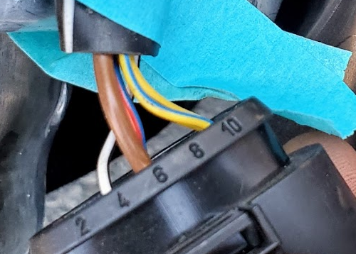
OK, now for the hardcore stuff. Important note: on my 2019 Cayman GTS with base lights, the headlight connector has 10 pins. That made things easier. In contrast, the 911's base headlights have 14 pin connectors, which require transferring every wire to the new 10 pin connector. On older 718 models, you may see a 14 pin connector and will have to check chris2�s guide to figure out the order of things (PIWIS II also includes wiring diagrams).
Stock 10 pin headlight connector. The brown ground cable will need to be moved to position #8.
Repin the Ground Wire
Once the headlight is out, disconnect the headlight connector. Next, unlock the wire terminals inside the headlight connector by pushing outward on the notch of the pink plastic tab inside the connector housing (see picture). You can use a non-marring plastic tool for this if it has a sufficiently small/thin point. Otherwise, use a flathead screwdriver. Remember to push this back in after you�ve finished all of your wiring work. (By design, If you don't lock it, the connector will not snap into the headlight. Likewise, if you can't get a wire out, you probably have to adjust the tab slightly).
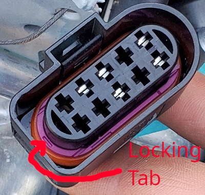
Reverse view of the headlight connector. To extract wires, first push out the locking tab as pictured, then insert the JPT extraction tool (or tweezers) from this end.
Using your JPT terminal extraction tool (1-1579007-6 or suitable tweezers), remove the brown ground wire from pin 6 and move it to pin 8 after popping out the silicon seal (use a wire hanger or similarly narrow, blunt object). To remove the ground wire, insert your tweezer tool into the reverse side, flush with the metal terminals and push inwards until it stops. This will pinch the metal terminals together, allowing you to pull out the wire. If you do not have PDLS, this is the only wire you have to adjust on a 718 with a 10 pin headlight connector. Hurray! Once moved, plug the now empty #6 slot with the silicon seal that you popped out before.
Make CAN Crash Data Wires
These wires are used to communicate with the CAN bus. They will connect to the leveling module on one end and the CAN Gateway on other (via wire taps). I tapped the Entry & Drive wires, which are located behind the frunk liner (the liner piece that�s flush with the bumper). See pic in the Wire Tap the CAN Crash Wiressection.
Cut off two new wires from the spindle you purchased. They will by used for the CAN crash high and low data connections. Crimp one end of each wire with the smaller terminals (144969-1) and set aside for later use with the leveling module. Remember to be consistent about wiring color code on high / low connections.
Make CAN Private Data Wires for Each Headlight
These connections facilitate communication between the leveling module and the two headlights. If you accidentally transpose one of these wires with another, PIWIS will not likely see your headlight modules and throw this cryptic coding error: �No relevant programming rules found for left/right headlight controller.� (In PIWIS III, the error is in English, II is in German).
Take two twisted pairs of wire (four wires total) and crimp them with the larger MQS terminals on one end, and the smaller terminals on the other (see instructions below). This is a low voltage/current line, so it doesn't matter electrically, but to obtain a proper seal, you should only use 18 gauge or higher wire. Make your own twisted pair by attaching the ends of two wires to a drill or kitchen mixer, then hold the other end and let �em twist. Use cable ties to keep them from untwisting.
Loom each pair of wire with fabric tape to protect it.
Route the wires into the frunk. Porsche has pre-cut a number of large holes on the sides of the frunk (near the top) that lead into the headlight area. At least one such hole on each side has a soft black silicone conduit around it. You should thread your wires through those. If you use the bare metal ones, your wires might eventually short as they rub against the metal edge. PSA: Over time, I noticed a fair amount of dust ends up coming through the bare metal holes into the frunk, so I covered them with aluminum tape.
You will crimp the larger MQS terminals on one end of each wire. Start by stripping back the wire jacket to expose a couple mm of copper wiring. Then, insert a blue silicon seal (plug) over the wire jacket, and crimp with the front tab over the bare wire, and the rear tab over both the wire jacket and seal. I had to stretch the wire seal hole a bit with a hole punch tool, otherwise threading the copper was impossible.
Install the newly crimped wires into the appropriate positions in the headlight connector (see diagram).
Crimp the smaller MQS terminals on the other side of each wire using the same method as you did for the CAN crash wires, then connect them to the leveling module (see diagram).
Drill Holes from Frunk to Cabin
There is a black foam cable conduit, located on the upper part of the driver-side frunk interior, that you will need to very carefully drill through. A hole punch tool will not be usable because the foam will keep expanding and fill the gap. You should drill AWAY from the center as much as possible to ensure you do not hit any factory cables. See pic below. You should have a vacuum handy to clean up the foam bits. When you�ve finished the project and verified that everything is working, fill in the gap with silicone RTV sealant.
Add New Fuses and Run Ignition-Switched Power Wires
Cut Three New Wires for TERM 15 (Ignition-Switched) Fused Circuits (Row D)
You will need to make three new wires, each of which will be run to empty slots in the ignition-switched (TERM 15) section (Row D) of your fuse box: one for each headlight (15 AMP), and one for the leveling module (5 AMP). The two headlight power wires should have the larger MQS terminals crimped on one end. The leveling module one should have the smaller terminal crimped on one end. Route the headlight ones into the frunk through the same black conduit you used for the CAN Private cables earlier.
Add Fuses to Driver-side Fuse Box
You may be tempted to just use wire taps for power, but I wouldn't recommend it. Adding a fused circuit is a fully reversible process, safer, and looks way more professional.
Pick three empty fuse slots in Row D (TERM 15), which is the bottom section. Slots 3 (�Left Headlight�), 8 (�Right Headlight�), and 10 (�Seat Ventilation�) are empty on my 718, but if you have seat ventilation, then #10 would not be empty. If you don�t have a third empty slot, you may use a fuse tap instead (on either #10 or #2 � both are 5 AMP). Only the leveling module should be connected to it, as the headlights need 15 AMP fuses. (That's how the headlights are factory wired, anyway).
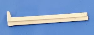
The space around the fuse box is very tight and there�s very little slack on any part of it. You will have to wiggle things until you've partly rotated it around to access the other side. First, pull the fuse box to dislodge it from its mount. Remove the back cover. Next, you�ll need to remove the long, white plastic locking "spine" that runs through the fuse box. Once removed, it looks like this:
Cut the Volkswagen repair wires in half. The terminal-crimped end will plug directly into the fuse slot. Once you�ve added a fuse blade of the appropriate amperage, it�ll be fully operational. As for the other side of the wire, you�ll have to be creative. I soldered each end to the corresponding new wires created in the �Cut Three New Wires for TERM 15� step above. If you bought the fuse terminals themselves instead of the repair wires (see link in the parts list above), you may be able to crimp the terminals directly to your new wires. That would be ideal, but I didn�t try this option, so I can�t tell you what gauge/crimp tool is compatible with these terminals. Butt-splice crimp connectors are also an option, if you can find one that fits the wire gauges of both sides. (000979135E is a skinny wire, while 000979227E is thicker � I used the skinny one and soldered it to my 18 AWG wires).
Snake your finished power wires through the holes you drilled in the frunk and battery compartment area. The wires will be poking out around the driver footwell area, �conveniently� just above the fuse box. Pull them through, then connect to the chosen fuse slots. Close up and remount the fuse box, then add your two 15A and one 5A ATO fuse blades to complete the circuit. Looks super clean, doesn�t it!?
When testing the wires for voltage, the engine must be running.
Finish the Leveling Module
You will need to make a new ground wire for the leveling module. It only needs to be about a foot long. Crimp or solder a ring terminal on one end and a small MQS connector on the other. Pull off the black plastic cover covering the ground connections at the bottom of the frunk (you'll see a bunch of brown ground wires). Attach the eyelet-end of your new ground wire to a suitable metal thread. (Painted threads are fine -- Porsche uses conductive paint). Plug the MQS terminal end into pin #24 of the leveling module connector.
Using the diagram above, connect the remaining wires. Take special care; you don�t want to get them out of order. Frustratingly, the numbers printed on the corners of leveling module connector are insanely small. You may want to get a magnifying glass. In the diagram, "Can High" and "Can Low" are the CAN Private High/Low wires you made earlier � not to be confused with the CAN Crash data wires.
If you make a mistake, it�s a bit of a challenge to get the wires back out of the leveling module connector. I had to use dental tools to push the terminal down and out-- that is, you can�t just push it, it�s blocked by plastic edge that you have to push around. The JPT extractor tool is too big for these pins.
Once you have all the wires hooked up, insert the connector into the blue leveling module housing. Secure the wires by looming them to the housing (you want to reduce any pulling pressure on the wires). Close the latch to complete the module. We�re almost done!!!
Wire Tap the CAN Crash Wires
If you plan on adding the automatic high-beam camera, I recommend tapping the CAN Crash wires on the CAN Gateway itself, as you will have to do that for the camera, anyway. PosiTaps will allow you to wire both the leveling module and the camera with a single set of taps. If you're not adding a camera, though, the easiest target to tap is the Entry & Drive wiring. However, I do not recommend using it because it's not connected to the CAN Crash bus segment, but rather CAN Comfort and could have unexpected behavior. I included a picture of what it looks like tapped at the end of this section (see: "Alternate CAN bus access" pic).
Whichever option you pick, you will need an additional set of twisted pair wires (22 AWG or thin jacketed 18 AWG). To access the CAN Gateway, first run wires into the cabin via the same conduit that you drilled for the headlight power wires. The Gateway is located near the OBDII port, but to reach it, you will have to move the Knee Airbag mount out of the way. To do so, remove the screw from the left-hand side of the knee airbag cover with a star socket. Unless you have a special low-profile tool, you won't be able to completely remove the knee airbag mount because the right-hand side's screw is blocked by a plastic piece. Instead, just push the cover forward. Once you've located the Gateway (see below), unplug it.
CAN Gateway unplugged
Remove the connector from the housing by pushing a narrow object through the hole you see on one side (see below). This will loosen the connector and allow you to slide it out. NOTE: Once you've pushed it out, it won't securely lock back into place for some reason. When you reconnect the plug to the gateway, just keep your finger on one side to prevent the connector from sliding back out. The Gateway itself will keep it secure.
CAN Gateway connector housing
Regardless of whether you're using the Gateway or the Entry & Drive tap location, you are looking for an orange/blue (high) and orange/brown (low) wire pair. On the Gateway, the ones you want are connected to Pin 7 (CAN Crash Low) and 17 (High). If you transpose the pair, the leveling module will not be recognized. Tap the two wires with PosiTaps and connect your twisted pair. If you've never used PosiTaps before, make sure not to overtighten the end that punctures the Gateway's wiring. You should only tighten until you encounter just enough resistance to pierce the wire insulation. Test with a multimeter for continuity, to be sure.
Reinsert the connector into the connector housing and plug it back into the Gateway. Connect the other end to the leveling module's CAN Crash low/high pins. Test the voltage on the leveling module's CAN Crash pins (ignition ON): low should be ~2.3V and high ~2.7V. They may not be exactly these voltages, but ensure that the CAN high pin has a higher voltage than the low one. If it doesn't, you likely have your wires crossed. If they both read 2.5V, you may have a short.
Alternate CAN bus access: Entry & Drive, located in the frunk (flush with the bumper on the driver side)
Optional: Mount Electronics to New Windshield Mount
Reminder: if you already have the Lane Departure Warning option, you do not need a new windshield or any of the camera/antenna parts in this guide; they are already present.
This requires a new windshield. Have the windshield installed first, since the required mounting bracket comes pre-installed with the glass.
Remove the various covers: both the 2-piece plastic cover over the windshield mounted electronics (they connect down the center), and the cover above it with your interior lighting buttons. To remove that second cover, push a credit card behind the upper corners of the cover. There are metal spring-like tabs there that take a decent amount of pressure to push in. You'll have to push in and pull the cover out simultaneously. It takes some finagling.
Plug in the camera heater, GPS antenna, and mobile phone antenna. The camera heater will slot into the triangular cut-out in the mount on the left-hand side (see pic further below). Directly below is the fully assembled set of electronics, including the camera (instructions for the camera are in the next section)
Camera far left, GPS antenna middle (buried under wiring), new mobile phone antenna on the far right.
Close-up of the GPS antenna mount position. Note the black plastic tabs keeping it in place on either side. It takes some finagling to squeeze it in there (you have to push on the right hand side's clips a bit to get clearance to wedge it down).
The camera cover/heater snaps into the triangular opening pictured here. It'll leave a small opening at the top for the camera lens. The camera has metal prongs that slot into 2 indentations on the left-hand side, and 1 on the right
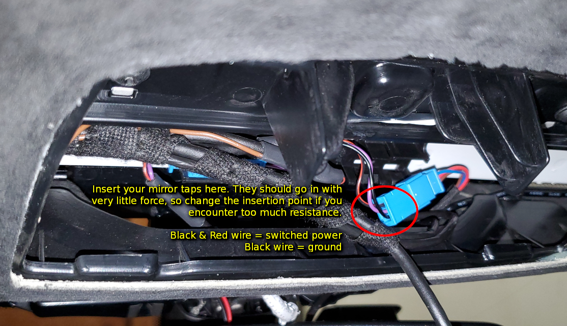
Using a reversible MirrorTap (see parts list) or a regular wire tap, tap ignition switched 12v (Term 15) and ground (Term 31) connections on the right-hand-side blue connector (see pic below). If you have a GT4 or certain models, you won't have that connector and, therefore, won't have a switched power source up in the mirror assembly. In that case, you'll have to run a wire to the fuse box, instead. Install the TERM15 and ground to appropriate locations in the camera connector, crimped with the smaller MQS terminals.
Wire the heater connections by cutting two wires approximately 4 inches in length, then crimping both ends with the smaller MQS terminals. Install to appropriate positions on the camera connector, then install the other end in to the 8D0-972-623 connector. If you bought the 8D0-972-623 connector off of eBay, chances are it's already pre-wired on the connector end and ready for crimping on the other.
Resistance test your ground connection (ignition OFF) with a multimeter. It should read 5 ohms or less. If it's much higher, ensure your mirror tap prongs are sufficiently pushed into the connector; they should slot in almost completely.
Tap (with twisted pair wiring) CAN crash low and CAN crash high from the CAN Gateway. This is located in the driver's footwell above the OBDII connector, on the underside of the steering column. The required wires are orange + brown and orange + blue
Loom wires with fabric tape.
Route new can crash wire up the A Pillar and into the mirror assembly. To remove the A Pillar cover, pry it semi-loose by wedging your fingers between the window and the edge of the A Pillar and pulling back a bit. To remove it, you'll have to unlock the on the ball and post locking mechanism inside by following this guide.
Crimp the CAN Crash wires with MQS terminals and install to appropriate positions in camera connector.
Mount the front camera. It will be a very tight squeeze. The thick set of wires going to the rain sensor, in particular, will give you a hard time. If you pull on it too hard while moving it out of the way, the rain sensor may get disconnected. Push down on the sensor plug after you've finished just to make sure. The only way I managed to more or less line up the 3 metal prongs on the sides of the camera with the plastic mounting grooves is to do so without connecting the camera wiring plug. This will give you more maneuverability (though it does make plugging in the camera connector much more challenging). Note that the prongs don't seem to slot very far into the grooves; they kind of rest on the edges, just barely inserted. I couldn't do any better than that, anyway.
Once the camera has been seated securely, plug in the connector. You'll have to finesse this a bit since there will be lots of wires in the way.
Once you have PIWIS II connected and working, follow the steps below to code the headlights. If at any point PIWIS asks you whether you want to create a VAL, select "No," as it�s a time consuming step.
Set ignition to ON (but engine off)
Set lights to Parking Mode (coding will fail if you forget to do this)
In PIWIS II, navigate to the Diagnostics menu, then select 982
Click on Gateway
Select Maintenance / Repairs tab, then Actual / Specified Configuration
Click the Accept New Configuration button (nothing much will happen in the UI � you won�t see a confirmation or anything).
Go back to the Overview tab and select Left Headlight (or Right, either way it will code both in sequence)
Select Maintenance / Repairs tab, then Headlight Commissioning
Follow prompts and select Execute for each operation. Coding will kick off and take several minutes. During this time, you will be asked to switch the ignition off and back on again several times; PIWIS will detect when you have done so and continue. Unless your battery voltage is very low, you can safely ignore the warning about connecting a charger to the car. (A sign that your voltage is very low is that the eco engine start/stop function wasn�t working the last time you drove).
If completed successfully, restart the car one more time and check out your sweet new LED lights!
Optional Final Step: Code and Calibrate the Camera
So, the camera coding proved to be tricky to do in PIWIS II because the headlight commissioning step left things is a slightly odd state. It seems that some Xenon non-PDLS+ options were left enabled in the Maintenance of Vehicle Data section. When I tried to code the camera initially, PIWIS saw that there was a mix of LED and Xenon options (i.e. multiple values) and quickly threw an error: "Multi-valued variant found." If this happens to you, click on the Additional Menu buttonat the bottom of the diagnostics screen, then select Maintenance of Vehicle Data. Here is where it gets difficult in PIWIS II: none of the 3 letter option codes have descriptions, whereas PIWIS III does. Here is a list (taken from PIWIS III) of what you do and don't want (you can click the checkbox next to the code to enable/disable it):
LED/PDLS+ Codes (Enable)
XEY LED Headlight Darkened + Dyn. Cornering Light
8G1 PDLS+ High-beam Assistant
852 PDLS+ High-beam Assistant (same name as option above, don't know why it appears twice or whether it matters)
Xenon Codes and Miscellaneous (Disable)
601 Bi-Xenon
603 Bi-Xenon + Dynamic Cornering Light
604 Bi-Xenon Top + Dynamic Cornering Light
632 Dynamic High-beams (this option conflicts with the Highbeam Assistant option above and will trigger the multi-valued variant error, as well)
800 Bi-Xenon/Dyn. AHBA (Black)
8G2 PDLS+ Dynamic High-beams
To code the camera in PIWIS II* after addressing the issues above, follow the steps below:
Open Diagnostics. Click on Front Camera, Instrument Cluster, and Front-end Electronics, then hit Next
Click on Codings adaptations
Manual Coding
On the next couple screens, ensure the options you want are checked in the Installed column, then keep hitting Next until PIWIS starts the coding process. Rather inexplicably, the Instrument Cluster will sometimes fail to code the first time. If you see check-marks indicating that the camera and front-end electronics were coded successfully but not the Instrument Cluster, re-run the coding process. It often succeeds the second time.
Now for the static calibration... Unfortunately, this cannot be done without a special, $30k+ calibration rig (examples: Bosch ADAS or Autotel ADAS rigs). Many of the better auto glass shops have the equipment to perform the calibration. Porsche dealers can also do it, but they charge an arm and a leg (I was quoted $950 vs. $200 from an indie). Once calibrated, your car's VIN will be coded to the camera and the one remaining fault should clear.
* Another PIWIS II challenge is that the tool may not even have the coding rules available for the instrument cluster and front-end electronics modules if your car is MY2018+. If you see an error like "Control unit variant instrument cluster in MCR data not found," that likely means you'll need access to PIWIS III, instead. A well-equipped indie shop may help you to code these modules, if you explain the situation.
Last edited by martopoulos; 11-22-2023 at 05:57 AM.
If you get coding errors, make sure you haven't transposed any High/Low cables. Triple check everything. Use a multimeter to make sure your TERM 15 cables are really supplying voltage (note: they won't unless the engine is actually running).
Ensure that your VIN is present under the Maintenance of Vehicle Data menu. If blank, it could fail to code. I'd like someone to confirm this for me, though.
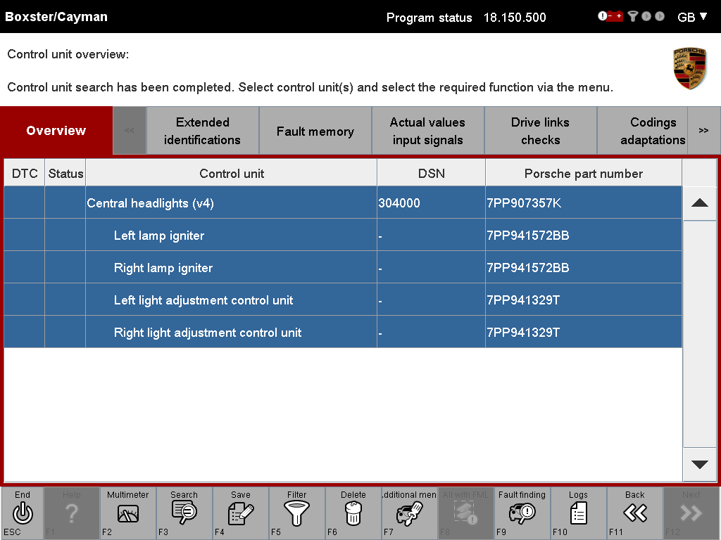
The Central headlights display in PIWIS should look like the screenshot below. If any of the cells under the Porsche part number column are blank, something is wrong. (Transposed wires, bad modules, etc.)
Last edited by martopoulos; 08-21-2020 at 05:56 AM.
As someone who has the base headlights, I always wondered whether this upgrade was possible but didn’t want to be the first to try it. I’m glad you did. Thanks for this very detailed guide!
Two notes: even though everything that's expected to work seems to be working, and the coding completed successfully (according to PIWIS), I am still getting an error about the headlight control module. It's possible that it's related to the missing camera, though, if that is considered a "module." Chris2 said he gets an error about automatic highbeams being unavailable on his 991.1, but I'm not sure whether it explicitly said that or if it's just a generic control module error like this one. It's the only error I get, though, so I suspect that's what's going on. Until my windshield gets a nasty crack, though, I won't be sure!EDIT: This is not why. I never installed LED headlight fans because I didn't know they were sold separately. Both fans are faulting and I think/hope that is the sole cause of this instrument cluster error.
Second, it's possible to do this entire project without a single wire tap, making this a fully reversible job (minus the holes you put in the foam cable conduits). If you build a Y-cable with the correct receptacles for MQS terminals, you can remove the CAN Crash wires from the CAN gateway and plug the Y-cable into the gateway, instead. Over in the 991 forum, drcollie is figuring out what all of the part numbers are. I plan on doing this for the camera CAN Bus connections. EDIT: This is possible but we never figured out the part numbers. It would need some kind of receptacle for the smaller MQS terminals, but good luck navigating the TE Connectivity catalog.
Last edited by martopoulos; 07-01-2022 at 09:03 PM.
As someone who has the base headlights, I always wondered whether this upgrade was possible but didn�t want to be the first to try it. I�m glad you did. Thanks for this very detailed guide!
Yeah, I definitely wish someone tried it before me That said, the 911 guide was really close. A few things about it were more complicated, even.
After looking at this I have decided that the easier things to do would just be to build the entire car from scratch using a 3D printer 🖨!
You�re a very brave soul to try this headlight upgrade..............
Haha! I definitely don't want to attempt anything this complicated ever again. That said, I learned a lot of useful electrical stuff!
I really wish Porsche hadn't changed their headlight design to require bumper removal. It made things sooooo time consuming. But hey they're hard to steal now ...
Last edited by martopoulos; 08-21-2020 at 07:11 AM.
I just want to say, that may be the most thorough and helpful diy explanation I've ever seen. Will I try it? No way. But it answers so many questions. Enjoy your new headlights.
I think I will stick with upgrading to the 35 watt xenon bulbs and ballast when I get around to it. (that's more my speed, and I guess will have to do.)
Great write up, not for the faint at heart as you say. Also thanks for the pointer on the PIWIS, I was wondering how you would get all the coding done.
Great write up, not for the faint at heart as you say. Also thanks for the pointer on the PIWIS, I was wonder how you would get all the coding done.
Thanks! Yea , it's a great tool, I highly recommend every owner gets one. I also used it to effectively disable my spoiler when I installed a fixed GT4 style one, so I don't even consider it a cost of the project.
Thanks for an incredibly through, insanely detailed project. I wondered about spending the extra money for the LED PDLS on my 18 CGTS. After reading everything that you did, it was worth every penny to have the Porsche factory do the installation.

 08-21-2020, 04:22 AM


 That said, the 911 guide was really close. A few things about it were more complicated, even.


