X-Post: ISIS Intelligent Multiplex Systems (race car wiring alternative)
 08-03-2009, 01:10 PM
#1
Former Vendor
Thread Starter
I've been researching wiring options for my track car project. After choking on the price of the newly announced PDM units from MoTeC, I started looking for an alternative, and found ISIS Intelligent Multiplex Systems. It is less than half the cost of the MoTeC PDM setup, and about 25% more than a conventional harness from Painless, with many many advantages in terms of weight, programmability, flexibility, etc. etc.
I also found a very healthy thread (12+ pages) on http://www.pro-touring.com that gets into the usual pro-con discussion. Rather than distill all of that information here, I'd suggest that anyone interested take the time to peruse that thread. There are a couple of links to documented installs, along with two very informative videos.
More to the point, that forum is currently running a group buy on the ISIS 3-cell starter kit. The group buy is open to participation through 14 August. I am 98% certain that I will be participating. Just thought I would extend the opportunity to the Rennlist community, as this could be a very attractive alternative to anyone working on a complete frame-off build like I am...
Anyone interested in participating in the group buy should contact wellis77 on pro-touring.com using his email address: wellis999 AT gmail DOT com
 08-17-2009, 01:01 AM
#3
Intermediate

Join Date: Aug 2002
Location: San Diego
Posts: 31
Likes: 0
Received 0 Likes
on
0 Posts
I wish I would have seen this before I ordered mine yesterday to get in on the group buy. Anyways I tried to find the thread on the link but no luck. Any additional leads on it would be a help. Thanks Andy
 08-17-2009, 01:26 AM
#5
Former Vendor
Thread Starter
Ordered mine. Jay and Mike at ISIS have both been very responsive to questions despite being bombarded (I'm sure). The total figures for the group buy ended up being 42 systems (!). I'm really excited to get my hands on the product and start laying out my electrical system.
08-21-2009, 06:59 PM
#7
Former Vendor
Thread Starter
Hmmmmm....wonder what's in here?!?!?
.
.
.
.
.
.
.
.
.
.
.
.
Master Cell || Power Cell

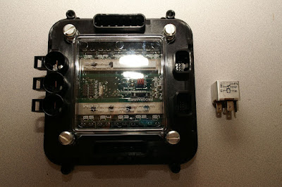
Fuse Block || inCODE


The whole shebang...well, except for all the wires-n-stuff
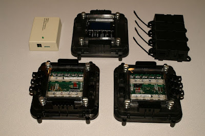
I included a standard Bosch relay in the photo to give you a sense of the size of these things. They're not little. Would be a challenge to hide in a car that you wanted to keep looking stock. But I don't care about that for the UWB...these should be great for a race car.
.
.
.
.
.
.
.
.
.
.
.
.
Master Cell || Power Cell
Fuse Block || inCODE
The whole shebang...well, except for all the wires-n-stuff
I included a standard Bosch relay in the photo to give you a sense of the size of these things. They're not little. Would be a challenge to hide in a car that you wanted to keep looking stock. But I don't care about that for the UWB...these should be great for a race car.
Trending Topics
08-21-2009, 07:01 PM
#8
Former Vendor
Thread Starter
08-27-2009, 08:21 AM
#9
Former Vendor
Thread Starter
In case anyone has any interest at all, I've been working on the wiring diagram for my build, which will involve a DTAFast S60 Pro and a Racing Technology DASH2 display. With a little help from the boys at ISIS, here is what I've come up with so far. Note that this diagram doesn't depict the "chassis" circuits (lights, etc.), just the primary systems for running the car. Here is the latest GIF image (click the image to go to my picasa album and use the zoom feature there to see it at full size) and link to the source Visio.
08-29-2009, 07:15 AM
#12
Former Vendor
Thread Starter
Here's a much improved diagram...lots of minor corrections, added essentially all of the circuits, cleaned up the routing, and tried to match as best as possible the color codes on the ISIS ins and outs.
DOWNLOAD -> VISIO SOURCE FILE
DOWNLOAD -> HIGH RESOLUTION PDF
Just to be clear, my car (a highly modified Porsche 924 Turbo) has a rear-mounted transaxle, and I have also developed a custom axle-driven alternator setup, which explains why I have some of the components depicted at the bottom of the page (representing the rear of the car...). I'm still sorting out how to connect up the wipers and climate fan, and haven't yet decided how to map a bunch of the switch inputs into the Mastercell, so those bits are still incomplete.

 09-30-2009, 12:50 PM
#15
Former Vendor
Thread Starter
I haven't updated this thread in a while, but the near-final iteration of my wiring diagram is included below. A couple of important notes:
DOWNLOAD -> VISIO SOURCE FILE
DOWNLOAD -> HIGH RESOLUTION PDF
- I separated the ECU, coil driver, injectors, and dash display onto two outputs on the front Powercell, as noted in the diagram. #3 output has the ECU and coil pack, #8 has the injectors, display, and control solenoids (boost & idle). This arrangement will prevent any possibility of overloading the critical ECU circuits, and will also allow me to switch from wasted spark (current plans) to individual Coil-on-Plug arrangement if I want to, without having to worry about overloading that circuit.
- Splitting the ECU, spark and fuel components over two circuits had a cascading effect on a bunch of other stuff because I now no longer have enough circuits on the front Powercell to run everything at the front of the car. Rather than purchasing another Powercell (they're BIG and expensive), I am going to run ALL of the parking lights off of the rear Powercell, and IF I decide to install a horn, that will also run off of the rear Powercell. Also, the "cooling circuit" (consisting of my electric water pump, electric booster pump, and thermatic fan) will also have to be run off of the rear #8 output. This configuration will require three conductors to be run from the rear Powercell to the front of the car. While not ideal, it's only three leads, so relatively minor inconvenience. Also, I am planning to install the rear Powercell in one of the rear seat wells, so those leads will only be a few feet longer than if they were attached to a front cell anyway.
- The backup lights will be wired off of the rear Powercell #7 output, with the switch on the transaxle being wired inline, rather than wired as an input to the Mastercell.
- If I run a dome light, it will be wired directly off the battery with an inline fuse and switch.
- After consulting with Mike at ISIS, I'm going to utilize the Mastercell's self-canceling turn signal feature, so this diagram reflects the appropriate changes as specified in the ISIS manual.
- I have one open circuit remaining on the rear Powercell (assuming I install a horn and a climate fan), which will be reserved for the later addition of an in-car video and data acquisition system.
- I still have a couple of Mastercell input assignments to sort out, but those shouldn't be any big deal.
DOWNLOAD -> VISIO SOURCE FILE
DOWNLOAD -> HIGH RESOLUTION PDF