When you click on links to various merchants on this site and make a purchase, this can result in this site earning a commission. Affiliate programs and affiliations include, but are not limited to, the eBay Partner Network.
Need help with spoiler harness wiring diagram for third brake light
I need a wiring diagram and physical locations for connectors for the wire harness associated with the rear spoiler lift mechanism.
I want to "fake out" the electronics such that the computer (really the rear spoiler's third brake light) to think that the spoiler is always in the raised position. It's my understanding that there is a upper limit switch on the lift mechanism and a lower limit switch. If the upper spoiler position is "tripped" then the spoiler's third brake light is energized. If the spoiler is parked (or in the lower position) then the fixed back windshield third brake is energized.
Presumably, by opening or shorting some wires, I can mimic the natural positions of the spoiler, and get the effect I want. I could also accept having both third brake lights energized - if someone has a technique for that.
Why? Because I've replaced the original spoiler with a fixed wing, and transferred the spoiler's third brake light to the wing.
Would someone be able to post a wiring diagram of the harness wires I'd need to test and modify? I'd like to do the wire modifications near a connector, probably near the non-spoiler end of the harness - would you be able to suggest where the spoilers lifting mechanism harness terminates in the body or engine compartment? A picture would be great.
Try here on my onedrive http://1drv.ms/1FKxuFk. Not sure how long the link will be active so pull down a copy. You want sheet 3B in the 2005 PDF
Thank you. I'm having trouble reading this screenshotted section, is there a way you can save in higher resolution or perhaps read and type the words and wire colors for this section? Very much appreciated.
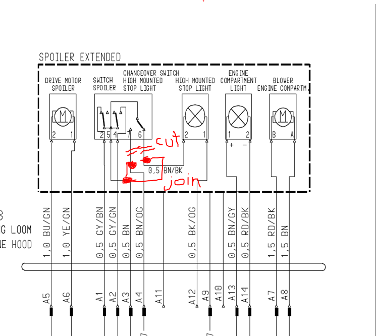
Hmmm. Maybe just the words and wires in the "spoiler extended" box near the top right.
Last edited by jchapura; 02-17-2016 at 01:33 PM.
Reason: updated request
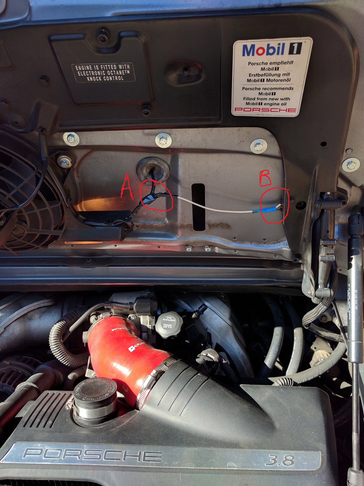
I did the mod. I decided to light-up both lights. Here's the mark-up for the mod.
The wing brake light harness is readily exposed in the engine bay (a cut and tie-in are there). The main engine lid harness is on the passenger side near the lid hinge and was easily exposed more for its cuts and tie-ins. So, I did not have to demount the wing to access anything in the area into which the old spoiler retracted.
In area A, I cut into the BN/BK wire from the wing mounted brake light. The now "free" end I just put on a piece of shrink tube. The other end, I elongated with the white wire that crosses over to the hinge area that's labeled ares B.
In area B, I cut the BN/OG wire and shrink tubed the end that was going towards/into the guts of the spoiler area. I cut the BN wire in this harness to make it easier to join it to the new extended white wire and BN/OG wire.
Last edited by jchapura; 02-24-2016 at 08:48 PM.
Reason: Added pic of electrical tie-in areas in the engine compartment
Cranking up an old thread.....so I have a fixed wing. Did the mod as described above. I did remove the motor for the spoiler. Heat shrieked the power ends etc to prevent short. Still gettin fault over 75 mph. Should I had left the motor in place with the limit switches? Don't see why that would make a difference.....
Also, PO wired in the third brake light and the upper light to come on at the same time. However the connector is dangling on the non-12v side. Where would the connector that has power be. It is not in the new wing.
I'm trying to correct what others have done, so it is much like a mystery.
I think you should have left the motor in and connected. The design of the wing I have is that the motor is still activated by the computer but the motor travel doesn't conflict with anything.
Maybe with a Durametric Pro you could disable the motor activation to then allow for removing the motor (and no fault).
To resurrect an old thread...my new to me car has a fixed spoiler. I spliced those three wires together and it didn't work. I'm wondering why I'm doing wrong...
Old thread, but i found it helpful while searching and can add some additional info.
Context: I installed a fixed wing with a third brake light and have been getting a "check raised brake light" error after disabling the OEM spoiler with Durametric Pro
One solution is to replace the harness with one from a car that has a fixed spoiler
If you have a fixed wing without a 3rd brake light you need: 997-612-670-71
If you have a wing WITH a 3rd brake light you need: 997 622 670 70
Not wanting to spend $140 on a harness, I started searching and found this thread.
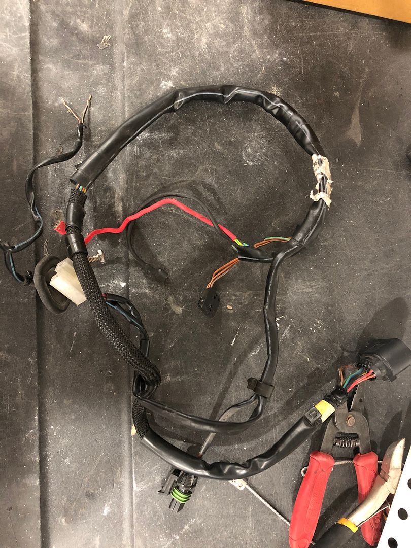
I got another standard harness off eBay for $30 and followed jchapura's lead on modifying it.
The wiring diagram can be a little confusing so i tried to simplify it:
Pin A3 - BN - Brown - Chassis ground
Pin A4 - BN/OG - Brown/Orange - Ground for spoiler brake light
Pin A12 - BK/OG - Black/Orange - Ground for fixed 3rd brake light
The micro-switches are used to provide a "ground" when the spoiler is up or down to the opposing brake light. By by-passing them, you can wire the light of choice, or both.
I chose to do both.
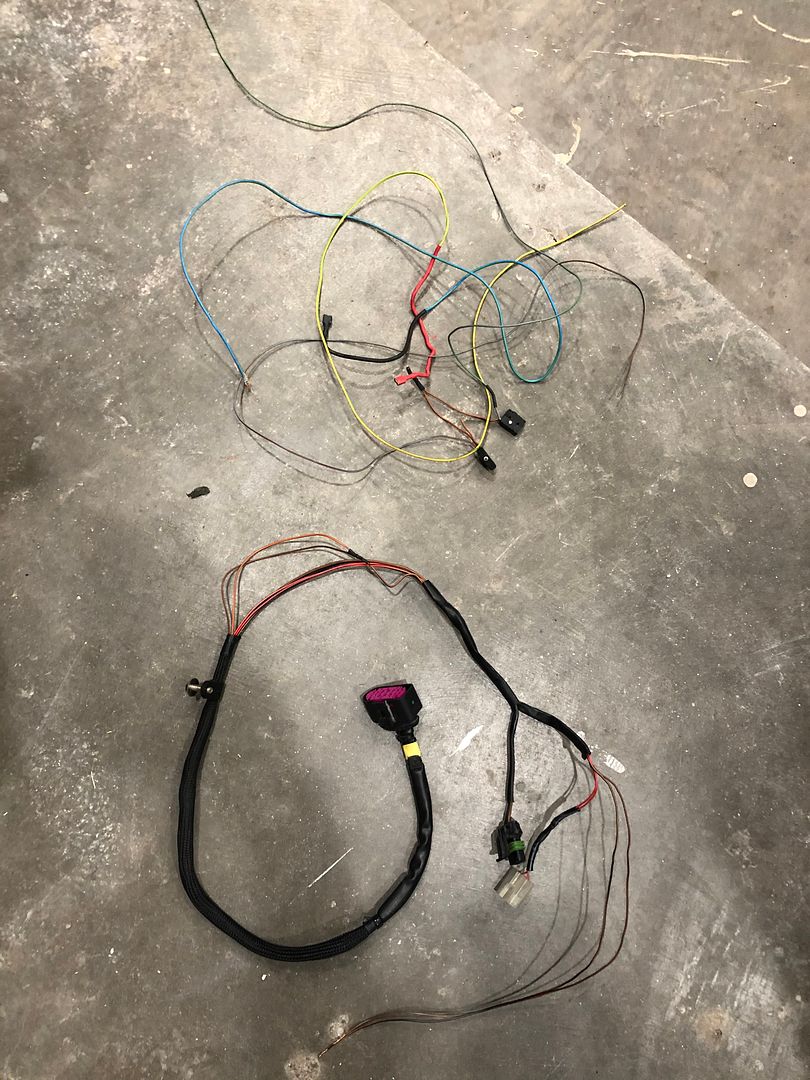
Harness before:
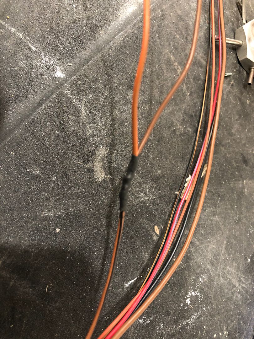
Sheathing removed, wires spliced:
While I was in there, I cut out the wires for the spoiler motor and micro-switches, leaving only the fan, engine compartment light and brake light
Option 1: Fixed wing WITHOUT a 3rd brake light you need 997-612-670-71
OR splice BN/BK to BN on stock harness
Option 2: Fixed wing WITH a 3rd brake light you need: 997 622 670 70
OR splice BN/OG to BN on stock harness
Option 3: Fixed wing WITH a 3rd brake light - Splice both BN/BK and BN/OG to BN to utilize both 3rd brake lights

 02-16-2016, 06:10 PM