When you click on links to various merchants on this site and make a purchase, this can result in this site earning a commission. Affiliate programs and affiliations include, but are not limited to, the eBay Partner Network.
Greetings. A few members requested that I post pics and updates related to my IMS Solution install on my recently acquired 2003 C4S.
BIG DISCLAIMER - READ THIS FIRST: This is my DIY install. I am not a mechanic. Throughout this process I have made a few silly mistakes that required me to go back and re-do things from time to time. This is not a reflection of the product at all but rather my unfamiliarity with it and the Porsche 996 in general. I happen to enjoy the process of learning to take things apart and put them back together - even if I make some mistakes along the way, but it is not for everyone. If you want an IMS Solution - I WOULD HIGHLY RECOMMEND ONE - and if you aren't 100% comfortable working on your car - I WOULD HIGHLY RECOMMEND having it professionally installed. Thus far my experience with the product, the tools and the people behind them has been absolutely first class.
In total this project took me just under 1 month. I made a few silly mistakes that added to the total time, and had to wait for parts to ship on several occasions. A shop, with a lift, and all parts on hand, that has done this before, could probably knock it out in a day or two. Me, laying on my back, with 15" of clearance from floor to underbody, never having worked on a 996 before, took a month - and it was pretty intense.
All together I put in the IMS Solution, replaced clutch/pressure plate/release bearing/flywheel and clutch slave cylinder, drained and replaced fluid in transaxle and front differential, replaced both front diff output shaft seals, replaced 1 output shaft seal on the rear and (obviously) did an oil change.
Post-project cost summary (my best guesses, not exact) - I already had a low profile floor jack, work light, one set of jack stands, air compressor, various sockets/wrenches/pliers:
Mandatory (in my opinion):
1,860.45 IMS Solution (after tax and shipping)
525 LN Engineering IMS Pro Toolkit and Supplemental
100 New synthetic oil
Other costs (if you don't have them already):
130 Harbor Freight Transmission Jack and 4 jack stands
25 HF Creeper (it sucked and I stopped using it half way through the project as the wheels didn't roll well)
100 Misc tools (various extensions, hex bits, torx bits, swivel heads, socket adapters)
25 3/8 drive air ratchet
30 Craftsman torque wrench (you can rent these free at AutoZone)
30 Spline grease, sealant, gasket maker, loc-tite, etc
17 c-clip pliers
Other parts (optional depending on condition)
550 Clutch, pressure plate and release bearing
850 Dual mass flywheel
160 Clutch slave cylinder
27 Brake fluid
50 Motive pressure brake bleeder
In addition, I replaced one output shaft seal in the transaxle and both output shaft seals on the front differential and replaced the fluid in both:
125 Seals
14 Seal puller
200 5 quarts of Porsche transmission fluid
30 Drain plugs and crush washers
-----------------------------
4,848.45
What follows is a summary. I'll try not to repeat information already readily available in the great Pelican articles related to transmission removal - but rather add my supplemental commentary and general status updates.
To begin with, I read that article along with the instructions included with the IMS Solution - multiple times. Then, I re-read. Knowing about things like the 10mm trisquare bolt ahead of time are a lifesaver. I ordered online and made a few trips to the store to get what I believe are all of the supplemental tools that I'll need including additional jack stands and transmission jack.
In addition, I had to order two toolkits from LN Engineering - the pro toolkit and supplemental toolkit. They are back-ordered for the IMS Solution but I found them in stock from ECS Tuning and had one at my door in about 36 hours.
To kick things off there is a pre-install checklist from LN related to engine health. I don't have all of the specialized tools necessary but I went through it and completed it the best that I could. I just finished a 900 mile drive and consider the engine to be strong and running very well. Removed oil filler cap while running to check for stall (it kept running). Drained oil and removed lower sump cover to check for debris (very small amount of clear/brown plastic - see pic) from what I've read people generally consider this to be normal. I also discovered that someone had installed a magnetic oil drain plug previously. No check engine lights or rough idle to speak of. The oil filter was also completely clear.
Before you begin it recommends disconnecting the battery. I rolled down each window a few inches and popped frunk and engine compartment prior to disconnecting battery.
Jacking the car up was a PITA, but primary because it was the first time I'd done it, and I was be extra cautious. I've found some instructions online but figured I'll include my process for good measure. To start with, there are only 5 jacking points that I used to get it up on jack stands. The 4 specially designated jacking points located just inside the wheels on either side of the car - and the rear (heavy duty) aluminum cross member just in front of the engine.
Break the rear lugs loose first - also put the car in gear / e-brake / use blocks behind wheels / etc. Be safe, slow and careful.
To start with I jacked one of the rear jacking points until the front of the car lifted high enough for a jack stand. Carefully lowered onto the jack stand and repeated the process on the other side with a slightly higher stand setting. Then, back to the first side, and back and forth until I had the car at a height I was satisfied with. Once the front of the car was in the air, my low profile jack could not reach the cross member without colliding with the bottom of the engine. To resolve this, I cut up a 2x8' into squares and stacked 2 under each rear tire (using the rear jacking points to raise). Now I could get the jack in from directly behind the car and raise (very slowly) the rear of the car up - while frequently checking the front jack stands to make sure they were staying in place. Set the rear jack stands to the same setting as the front and carefully lower down - the car should be sitting nice and level now.
Afterwards I removed the underbody plastic and took a look at what I was going to be dealing with.
That concluded day 1.
Day 2:
I had my dad come over to keep me company and stand guard in case the car happened to fall on me - at least someone would be there to call for help or try to jack it up. Then I removed the rear wheels (these things are WIDE!!!) and placed them under each edge of the car as an added measure of safety. I re-installed the lower sump plate with oil proof liquid gasket. The Pelican article mentions an aluminum cross member (not the one you used as a jacking point) but never specifically says to remove it .. you have to remove it. Two bolts, super easy.
Overall things moved slowly. I had particular trouble getting the shift linkage popped off (eventually used two screw drivers, one on each side to lever them off) and then the shift cables out of the bracket. Adding a little oil where they were being held helped and then it came down to leverage.
Having various socket extensions, wrenches and ratchets definitely helps.
The bolts on the CV joints were fairly straight forward and didn't really give me any trouble.
The slave cylinder bolts weren't terrible, the bottom one was definitely the trickiest.
Transmission bell housing bolts were hit/miss. Some were cake others were a royal pain. They're all different so make a template ahead of time to mark their position so you get them in the right holes when it goes back in. The top bolt - 12 o'clock position - was completely out of sight and the biggest pain of them all. I don't think its possible without a swivel connector and extension. I ended up getting it with a 1/2" drive ratchet, 6 or so inch extension, swivel, 16mm socket. I basically hugged the tranny (one around going up around each side) and used the metal lug nut wrench from the spare tire kit to lay between the extension and transmission so I had something to lever against.
That's it for Day 2. The next step is to begin loosening the actual transmission mounts and I wanted to wait until I was fresh for that step. Since this is AWD and the article is for 2WD models, I need to unhook the driveshaft that runs to the front of the car. From what I can tell - the front transmission mount/bracket needs to be removed in order to access the bolts to do this.
Cheers
Charlie
Last edited by charlieaf92; 08-24-2016 at 12:16 PM.
BTW, you've probably seen those already but just in case since you only quoted the Pelican article. There are 3 documents here you will need to read if you have not http://theimssolution.com/
Day 3 : the transmission is out. Beginning to fully appreciate the amount of work involved.
So far I would definitely not classify this project as easy. It is definitely straight forward, at least on paper, but given space constraints when working under the car it is not for the faint of heart. I'm also very glad I decided to stop last night and tackle actually splitting the tranny from the engine when I was fresh.
A quick note is that the article calls out bolt sizes, which is extremely helpful - however some of the sizes mentioned in the article don't match up with my particular car. Specifically, the bolts for the transmission bracket turned out to be 15mm for me (not 16mm). The nuts for the upper bracket are on studs and required a deep well 15mm sock (or wrench, but they're pretty tight so use a socket and larger ratchet if you can). I used a 24" breaker bar, 10 or so inch extension and swivel head on the 15mm deep well to break these loose - there are coolant hoses that get in the way but they can flex enough to get to what you need.
The procedure went much like described in the Pelican article with a few key exceptions related to the AWD system. The first is that I could not fully remove the upper transmission bracket. I believe this is because the AWD transmission is a bit longer, and there just wasn't space even with the front tilted down. It turned out it wasn't necessary to remove it completely so as long as you remove the bolts and its loose you're good.
The second difference was un-bolting the drive shaft from the transmission. This is actually much easier than I thought it was - and I spent quite a bit of wasted time because I didn't realize how they were coupled. First, you should remove the lower transmission mounting bracket - this gives access to the bolts holding the drive shaft to transmission. There are 6 bolts, three going in front rear to front and 3 from front to rear. The 3 from rear to front at hex head bolts and my hex head socket was too long to work with them. The good news is - you don't have to remove them! There is a rubber dampener/coupler between the two parts so you need only remove bolts from one side or the other - then you can pry them apart and you're good to go. The bolts running in from front to rear were standard 6 point heads and MUCH easier to access and break loose.
Once the drive shaft is disconnected it does get in the way a bit - but if you're careful and patient you can maneuver and lower the transmission without removing it from the front differential. Once the transmission was out I zip tied the drive shaft up and out of the way.
Which, brings us to getting the transmission out... I didn't put the car up high enough - and I knew this but I was paranoid about it falling off jack stands or being unstable trying to go too high. So, there wasn't a snowballs chance in hell the transmission was going to fit out on the transmission jack. The solution? With help, we lifted/rolled the transmission off the jack and onto a doubled up piece of cardboard. In order to get it out, it had to come out on its side because it is more narrow than tall - and I basically slid it out on the cardboard from the back corner of the car. Once out from under the car, we just picked it up and put it back on the transmission jack. The transmission itself only weighs 120lb or so, so with two people it isn't too bad if you can get a good angle to lift.
Once the transmission is pulled, the front of the engine has nothing to support it - and it doesn't stick out far enough forward to rest on the heavy cross member. As stated in the Pelican article you need to use a floor jack initially while decoupling the tranny and then place jack stands under it as a more permanent solution. This is where I made a small error that cost me some time. The jack took up most of the space below the engine and didn't leave me a place for the jack stands. I don't have another floor jack, so it took a little planning to figure out what to do next. Ultimately, I used the crank jack from the tire kit and some blocks of wood to take the weight off the main jack temporarily. Then, I slide a 2x8 that was roughly 24" long between the oil sump plate and my main jack. This gave me ample room to place a jack stand at either end of the 2x8 without them being in the way of my floor jack. Once the stands were in place, lowered the main jack out of the way and engine is supported.
Removing the pressure plate was actually quite a bit more difficult than I expected. My initial thought was that they would simply fall of when I removed the last of the six bolts, but that wasn't the case. I tried hitting the plate with a rubber mallet, prying, re-installing the bolts and loosening again, nothing worked. Eventually I pried it off with considerable force using the back end of a breaker bar - but it wasn't easy.
A safety note, and I didn't think of or realize this at the time, I believe the clutch dust is toxic and shouldn't be inhaled. Apparently spraying some water on the pressure plate and clutch prior to really starting to work will keep the dust from going airborne and getting in your lungs.
The clutch itself is in surprisingly good shape for 94,000 miles and the pressure plate bolts all came out relatively easily (I've read online these can be a nightmare) making me think it may have been replaced at some point (I didn't get any service records with the car). The pressure plate is still on the car (coming off tomorrow) but the spring/return action seems to be working perfectly. No pitting, glazing from what I can tell but there is a definite worn ring the same and width of the clutch disc. Once I get the pressure plate off the car I'll post some pictures - but right now I'm struggling with the decision whether to replace, re-use or resurface. I called a local machine shop and they said they can resurface dual mass flywheels - but I've read contradicting reports as to whether that is actually possible. Given the effort involved in this the last thing I want to do is to repeat it due to vibrations from an incorrectly resurfaced flywheel.
One last thing - I may have damaged or broken my slave cylinder yesterday when I removed it. The boot and rod/plunger were attached to the transmission when I pulled it out from under the car. I just noticed this and haven't looked at the cylinder itself (still in the car - but no fluid leaking so thats a good sign). I'm not sure if that piece just pulls out and can easily be re-inserted or if I snapped it off. If its broken, it is because when I was removing it I was actually pulling it away from the transmission housing towards the driver side of the car - this is wrong - it should be pulled towards the FRONT of the car. I mistakenly assumed it came out sideways because that was the direction the bolts came out. Its in a tough spot to see, so be sure not to make that mistake. EDIT: The slave cylinder was fine - I just pulled the boot off when removing it. (spoiler alert) Later, I destroyed it by mis-aligning it when reinstalling though.
On a side note, I noticed a small spot of oil on my garage floor when I first brought the car home and parked it overnight. It is about 5/8 of the way towards the front, on the driver's side. I suspected the front differential because I don't think oil is circulated from the engine anywhere that far up? Unless, is there an oil cooler in the front of the car? Although the diff is dirty I don't see anything obvious. My plan is to remove it as well, and drain/measure the fluid. If its full I'm thinking maybe its not worth worrying about - but if its low/empty I may have to invoke the drivetrain warranty that I purchased with the car.
Cheers
Charlie
Last edited by charlieaf92; 08-24-2016 at 12:21 PM.
Will Raby Engine Development warranty the IMS Solution if self-installed?
My company shares no part of the IMS Solution warranty, or etc. Its my inventions, but hasn't been my product since it hit the open market in 2011. We do not distribute, or sell any IMS Solution kits, or components. The same goes for any parts, we are developers, and builders of engines, and have nothing else to sell except our reconstructed engines.
That said, there's never been a single IMS Solution warranty claim, to my knowledge; but, only units installed by trained, Certified IMS Solution Installers are covered by a warranty.
The best warranty is the one you never need. Thats always my goal.
Kudos to the OP, this is NOT an easy task without a lift. If you need any help, email me at jake@jakeraby.com
Charlie,
Great write up and extraordinary attention to detail, but please stay safe. My father in law is a mechanic and has owned a shop for more than 25 years. He could share many heartbreaking stories of people getting seriously hurt or killed trying to handle major engine projects in their garages with just jack stands. Not trying to be a Debbie Downer or anything, just want to encourage you to keep it real and safe. And thank you sharing with the RL family.
Safety is paramount, not just from the car falling from the jacks, but also the weight of the transaxle once detached. Dealing with that is the biggest challenge by far. Wrestling it back into place, and aligning things is also not easy.
Also, pay attention to where the bolts go upon reassembly. If a long bolt goes in a position where a short bolt belongs, it can break through the chain housing of the engine, and create a big time failure. I have seen this one more and more the last few years.
Not to hijack this thread, but since Mr., Raby is here, i have a related question.
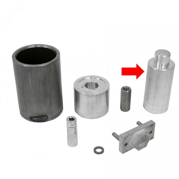
the installation procedure calls for the use of two sets of LNE tools.
The "IMS Pro tool kit" (which I used in the past and I understand its necessity) http://lnengineering.com/products/fe...-retrofit.html
And the "M96 MY06-08 Upgrade + IMS Solution Supplemental Tool Kit" http://lnengineering.com/products/im...-tool-kit.html
On every single installation instruction I have seen, out of that kit, only the �cup installation tool� is needed.
So what is the rest of the parts for (which some of them are already included in the Pro Kit), and is it possible to get only the "cup installation� tool.
I marked it in this pic just so we are all o the same page.
Thanks in advance, and keep on the good work Charlie.
Nice work, go careful and stay safe! Interested to see a pic of the slave cylinder and the part that you're concerned is broken... maybe in relation/orientation to the mounting surface you described it coming off of... trying to visualize.
Thanks Jake - I appreciate the advice. I used a cardboard template to mark where each bolt came from - but having the actual dimensions to reference will definitely come in handy just in case I mix something up or am unsure.
Also - the documentation and packaging of both the kit and the toolkit are outstanding, nice job putting it together! It seems like the actual install of the bearing will be the easiest part of this entire process.
Meirschwartz - I believe that the additional parts in the toolkit are used in the installation of another LN bearing product that the kit was originally designed for. It just so happens a few of them are needed for the Solution install as well.
On a side note. I just finished removing the flywheel. Initially I was going to have it resurfaced as a local machine shop that said they do dual mass flywheels all the time. However, saving 600-700 by resurfacing seems a lot less appealing after going through the process of removing the transmission so I've opted to buy a new flywheel because I will be very happy if I never have to do this again.
A note on removing the flywheel - a flywheel lock is not necessary if you have the IMS pro toolkit as it includes a crank shaft locking tool. With the engine TDC and locking tool inserted, I was able to break the flywheel bolts loose without much trouble. They use a T55 torx bit.
I could use some help regarding RMS / IMS oil leak. I've attached a picture of the block and it looks like something IS leaking, but it isn't obvious (to me) if its coming from the RMS or being flung off something towards it. My (limited) experience with rear main seals has been that if they aren't leaking to just leave them alone - especially if you don't have the right tool to install correctly, it may just create a problem that didn't exist before. Hope someone can help give some advice on this - is it stupid not to replace the RMS? Does it look like this one is leaking?
Thanks
Charlie
Last edited by charlieaf92; 07-21-2016 at 03:46 PM.
Hi Charlie
Looks like the leak is coming from the IMS cover, so it will be gone once the installation is done.
The RMS looks like it was updated, and so are the case bolts.
anyway, if you decide to replace it, i will let you use my tool, but only if you promise to lend me the IMS tool that i'm missing
 07-19-2016, 11:46 PM