When you click on links to various merchants on this site and make a purchase, this can result in this site earning a commission. Affiliate programs and affiliations include, but are not limited to, the eBay Partner Network.
This thread is going to be about testing the fuel system.
In Part 1, instructions are given for checking fuel pressure and volume.
In Part 2, how to check the electrical aspects of the fuel pump, fuel pump relay
and fuel injector waveforms will be shown.
Attached to this post is a PDF of Part 1, 5 pages from the workshop manual
covering checking the fuel pressure and volume, and the user manual for
the MityVac FST Pro. The user manual is included because it makes an
excellent reference for understanding the fuel system.
The remainder of this post will be the text version of Part 1.
Following this post will be pictures taken while performing the tests.
-bruce7
++++++++++++++++++++++++++++++++++++++++++++
Fuel System Testing Part 1 Rev 1
In Part 1, instructions are given for checking fuel pressure and volume.
In Part 2, how to check the electrical aspects of the fuel pump, fuel pump
relay and fuel injector waveforms will be shown.
Checking Fuel Pressure and Volume
This procedure is based upon the Workshop manual, but with one added test
for peak pressure. I hope to fill in the details where the manual is not clear.
Special Tools and Materials
Fuel pressure gauge
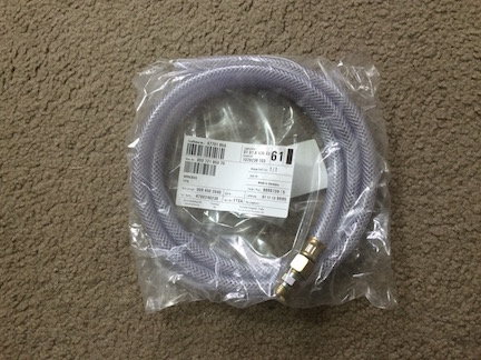
Connecting hose PN 000-721-950-70
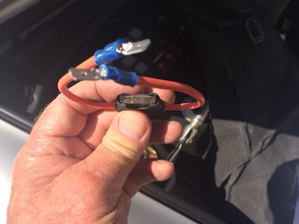
Fuse-protected shop made jump lead
Closing cap PN 997-110-218-00
Other tools are identified as they are used in the procedure.
Procedure Overview
Five tests will be performed in the order listed:
1. Static pressure
2. Peak pressure
3. Static flow
4. Idle pressure
5. Residual pressure
The first 3 tests are static, meaning the engine is not running. The idle
pressure test is the only test done with the engine running. The residual test
is a static test.
Procedure
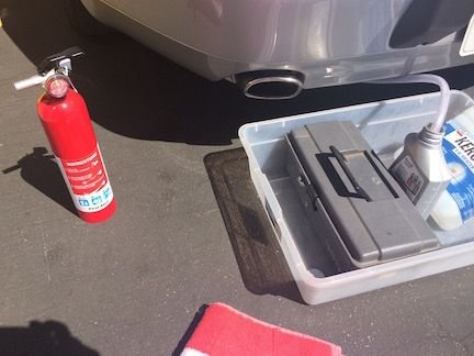
0. Place a fire extinguisher near the car for immediate access if needed.
1. Remove the rear blower assembly or the RS heater bypass tube if installed.
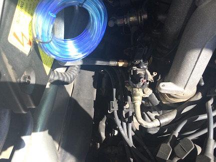
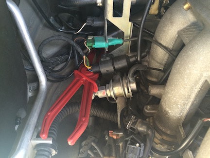
2. Remove the brass closing cap from the Schrader valve on the fuel rail
and discard. Place a shop rag under the valve to catch any gas that
may leak out.
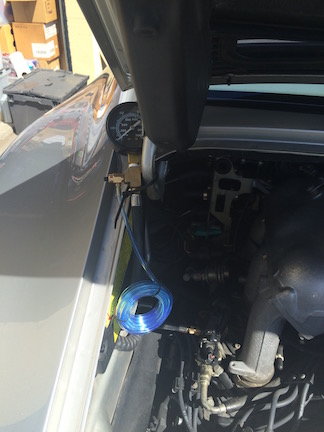
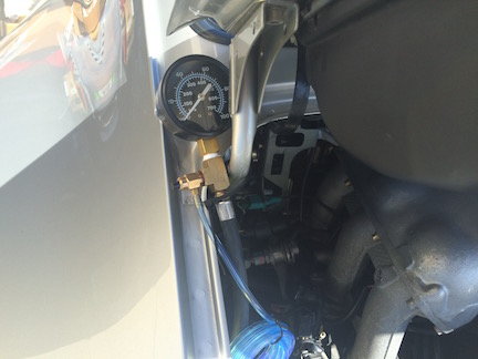
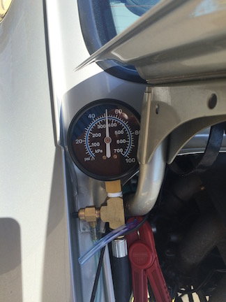
3. Connect the fuel pressure gauge finger tight then use pliers to snug up.
4. Secure the gauge dial in a visible location.
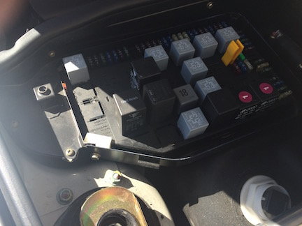
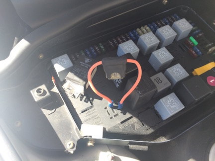
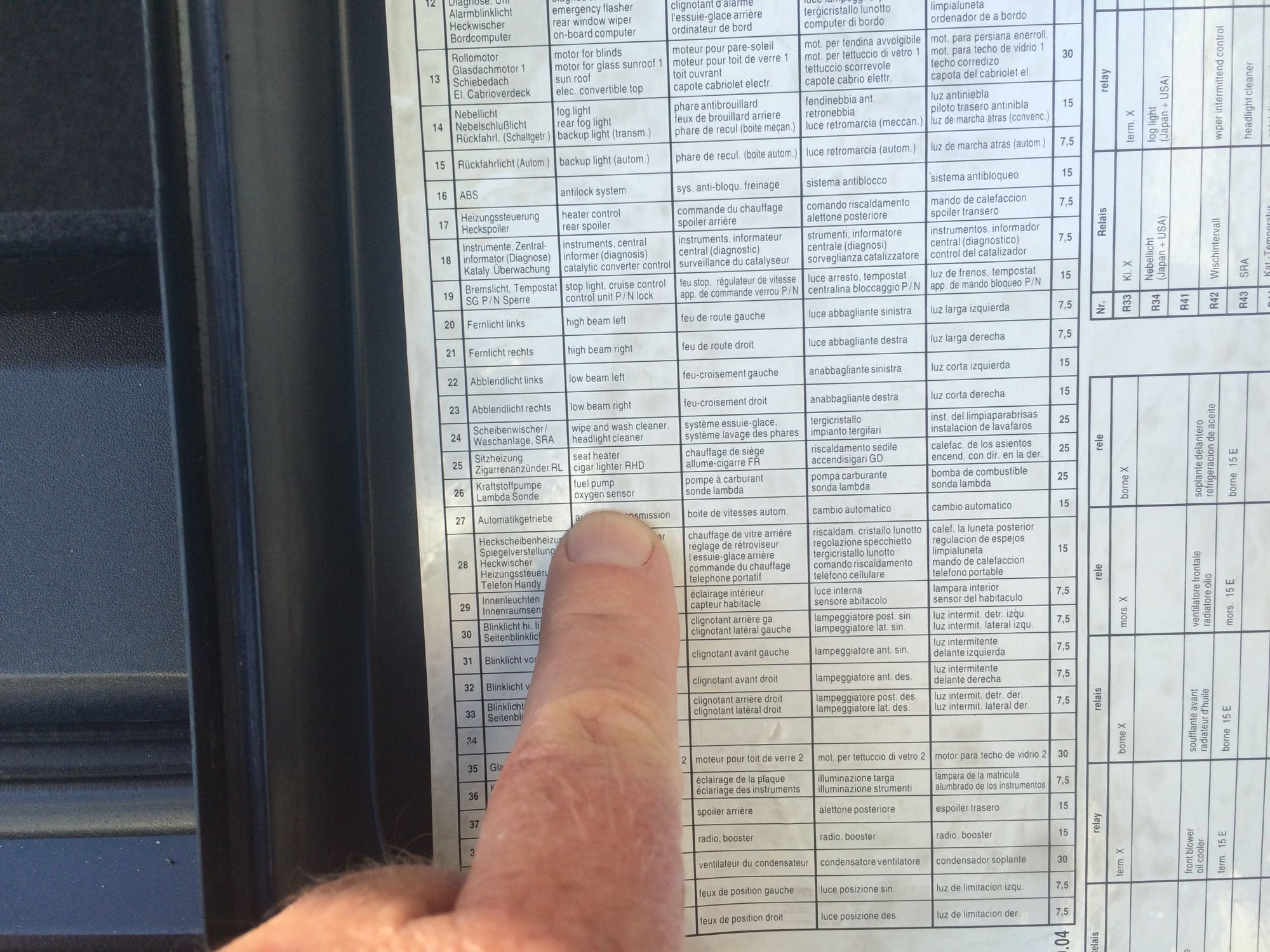
5. Remove the DME relay (R53) and jumper the fuel pump connecting
pin 3 (30) and 7 (87b) on the Central Electric System (fuse panel).
The pump can be heard running.
6. Check for fuel leaks in the engine compartment.
7. Record the fuel static pressure reading. Expected: 55 +/- 3 psi
8. Pinch the fuel return line momentarily using a line clamp and record
the fuel peak pressure reading. Expected: 75-100 psi
8.5 Disconnect the fuel pump jumper.
9. Bleed the fuel pressure gauge and then clamp off the clear bleed hose
to prevent leaking.
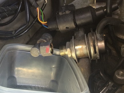
10. Place a shop rag under the fuel return line connection.
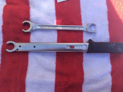
11. Remove the fuel return line connection using 19mm and 22mm open-ring
wrenches.
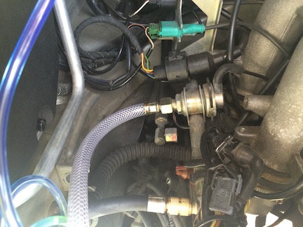
12. Connect the special tool connecting hose to the fuel return line connection
on the fuel rail. Tighten using the 19/22mm open-ring wrenches.
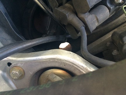
13. Remove the metal disk which plugs an access hole to the rear of the
heater tube.
14. Route the connecting hose through the access hole to a 1liter fuel catch
container. Secure the container from moving.
15. Jumper the fuel pump and start a stopwatch.
16. Stop the test by removing the fuel pump jumper lead when the 1 liter
bottle is full or 30 seconds transpires (whichever occurs first). Record the
volume of fuel collected and the time taken. Expected: 850 c.c/30 seconds
minimum.
17. Bleed off the fuel pressure gauge and then clamp off the clear bleed hose
to prevent leaking.
18. Dispose of the gas collected in the catch container.
19. Remove and drain the collection hose.
20. Reconnect the fuel return line and torque to 35 Nm.
21. Replace the metal plug into the access hole.
22. Replace the DME relay.
23. Start the engine and check for leaks.
24. Record the idle fuel pressure reading. Expected: 48 +/- 3 psi.
25. Shut off the engine and start a timer for 20 minutes.
26. Read and record the residual fuel pressure reading. Expected: 43.5 psi minimum.
27. Bleed off the fuel pressure gauge and then clamp off the clear bleed hose
to prevent leaking.
28. Place a shop rag under the Schrader valve and remove the fuel pressure
gauge.
29. Replace the closing cap with a new cap. Tighten finger tight then just
snug up a bit with the 13mm wrench.
30. Refit the rear blower assembly or RS heater bypass tube if installed.
My Results
Date of test: 3-26-2016
Time: 12pm
Temp: 77 degrees F.
Car: 1997 Porsche Carrera
Mileage: 120K miles
Fuel Pump Service Life: 120K miles
Fuel Pressure Regulator Service Life: 120K miles
Fuel Filter Service Life: 25K miles
All results meet or exceed the test specifications provided in the workshop
manual. System is operating normally, no faults found.
Although the fuel filter is nearing the end of the scheduled service life
(30K miles), it did not appear to impede fuel delivery.
The slight rise in residual pressure is probably due to heat from the engine.
Below is a diagnostic guide based upon Appendix B of the MityVac FST Pro
User Manual tailored for the tests performed in this procedure. The main
difference is that the MityVac FST Pro includes an Idle Flow test and no
Residual Pressure test.
Last edited by bruce7; 04-01-2016 at 11:40 PM.
Reason: Correct typo in step 5
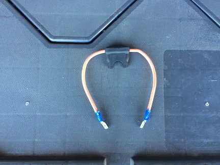
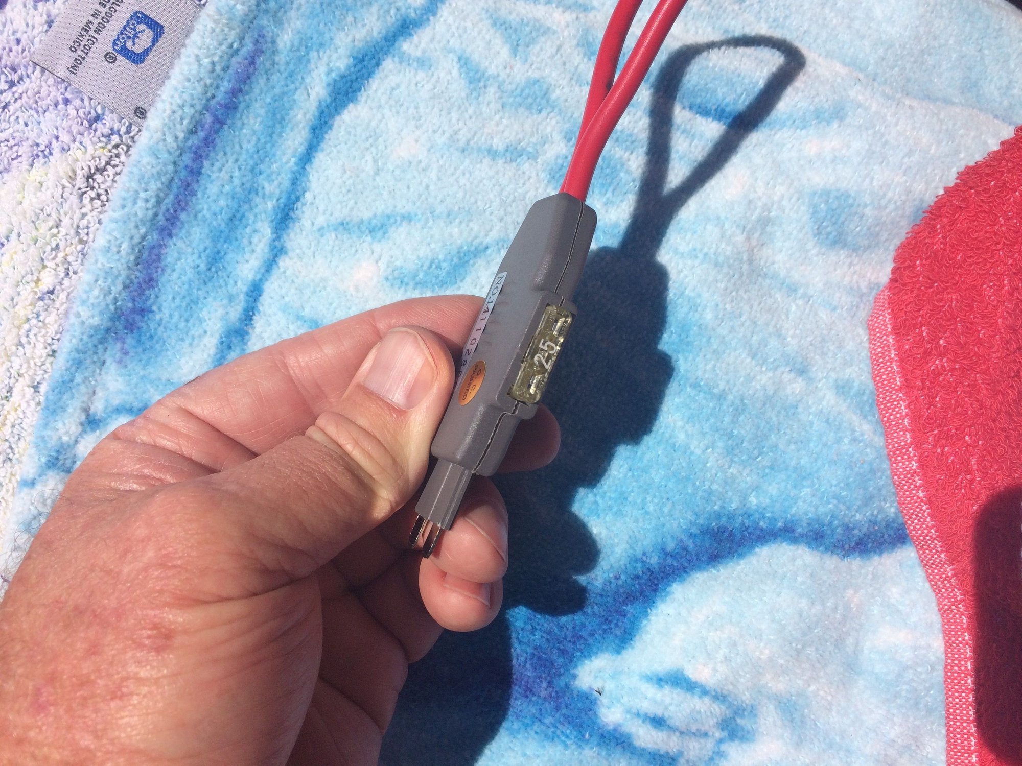
Bruce, Nice write-up. Couple of questions. What is the black piece called that holds the fuse? Where to buy? What is the make and model of the gauge used?
Bruce, Nice write-up. Couple of questions. What is the black piece called that holds the fuse? Where to buy? What is the make and model of the gauge used?
Thanks, Peter
Thanks Peter! I bought the fuse-holder at O'Reilly's. Here is a larger photo:
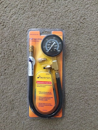
The fuel pressure gauge is made by Actron and is a CP7818. Here is a larger
photo of the one previously posted and a photo from Actron:
Some days I feel our cars are on the Same maintenance Schedule.
This Post could not have come at a better time!!
Since my Spring Adventure I feel my car is running "Quite Differently."
Not sure if car has a hesitation and perhaps I need Oxygen sensors but after installing the Fuel Pump the Car Feels very different.
Maybe its better>? Simply New & Improved - Time will Tell.
Now that some warmth is arriving North here I am about to try this DIY.
Thank you Again for taking your time to share !!
Tom
97 Carrera
Toronto, Ontario Canada
Hi Tom,
Glad that you're able to get out and do some driving. A hesitation could
be due to many things. How old are your O2 sensors? Without a scope it
is not really possible to assess how well they are performing. If you have
more than 80k miles on them then I would change all 4 of them out. I had
a situation where my car acted like it wanted to stall coming to a stop and
the computer would blip the throttle at the last second and catch it. Changing
just the front O2 sensors made it better but did not solve it. Changing the
rear O2 sensors later fixed the problem.
BTW, I have not written up the fuel system electrical testing yet due to work.
I have the data, just need to write it up. But finding the time is the problem.
But I will get to it and thanks again for the fuel pump commutator picture
which I will reference.
How to test and evaluate the 3 main electrical parts of the fuel delivery system
will be covered in Part 2, Electrical:
1. Fuel Pump
2. DME Relay
3. Fuel Injectors
Fuel Pump Testing
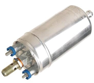
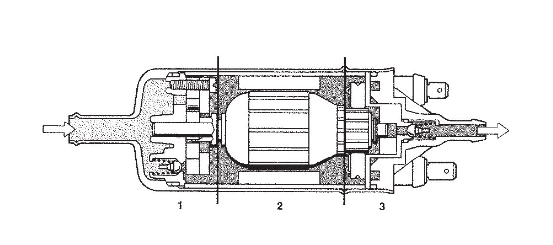
The fuel pump is an inline turbine-style pump made by Bosch.
Here is a section drawing of the fuel pump provided by geolab.
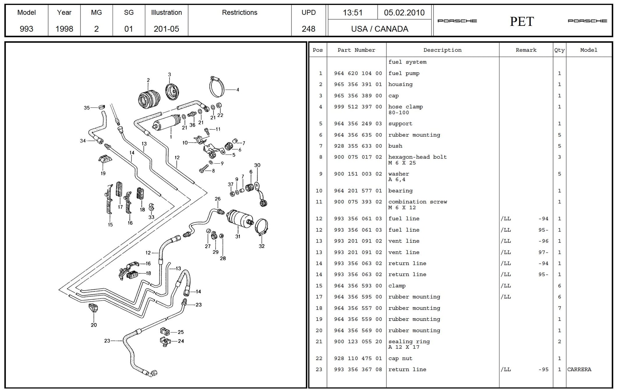
The fuel pump can be found in the PET catalog as item #1 from the page below.
The fuel pump is physically located just ahead of the passenger footwell and
behind the right front wheel. It is accessed through a panel cover from below.
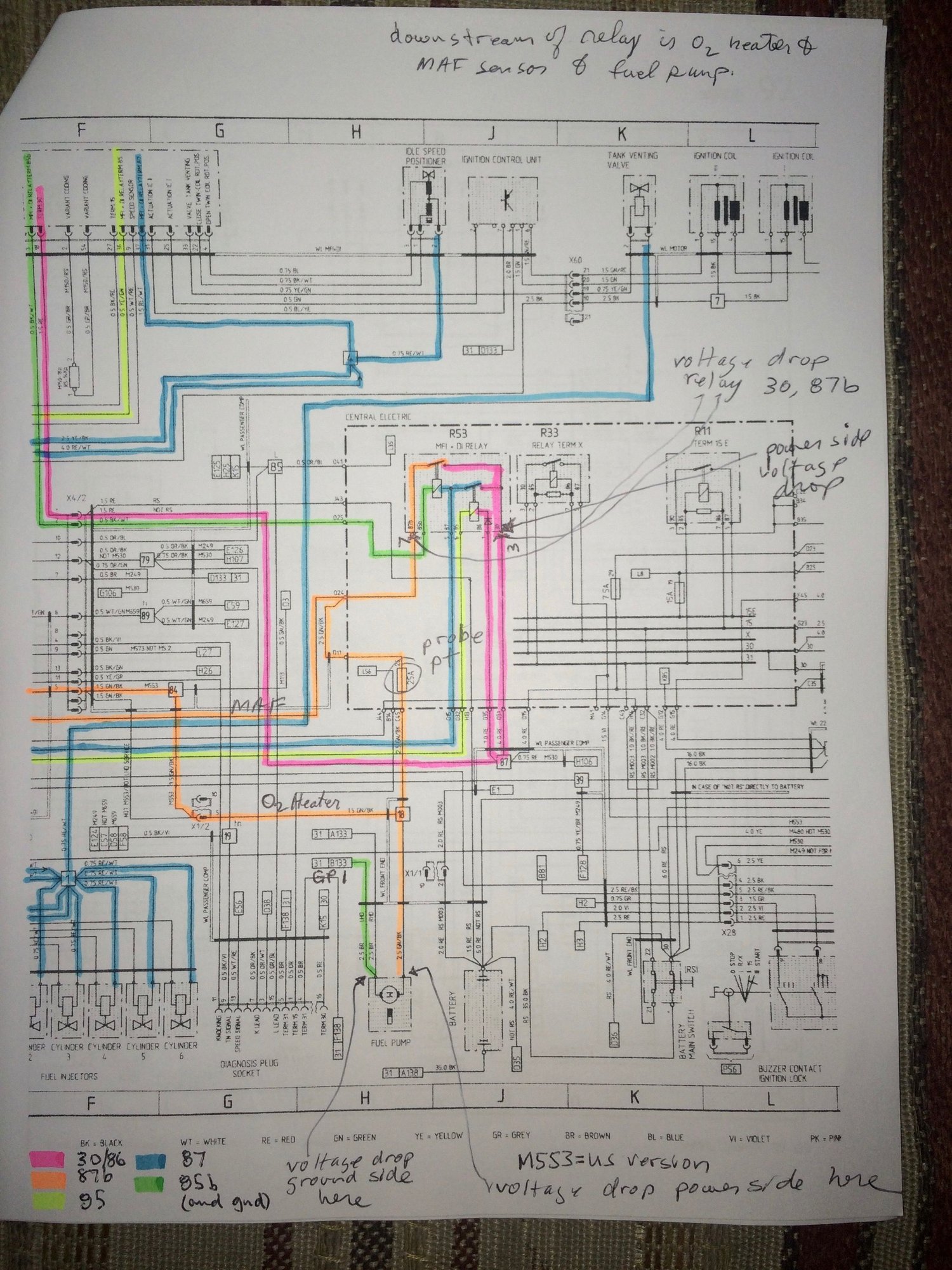
The wiring diagram for the fuel pump is shown below in sheet 5A. I have
broken it up into 2 pages and only show 2 of the 3 pages of sheet 5A that are
pertinent. In addition these have been annotated by tracing the wiring from
the DME relay using color highlighters. I took photos of the pages rather than
try to trace the wiring using an app mainly because it is a lot less work. Also
I would encourage you to trace the wiring yourself as it provides additional
insight into where things are and how they're connected.
Since the fuel pump is an electrical motor, we can tell a lot about the condition of
the pump by examining the current and voltage consumed. Using an oscilloscope,
the following measurements will be taken or calculated:
1. Inrush current
2. Operating current
3. Pump RPM
4. Voltage to the pump
Test Points
There are 2 places in which the test leads can be connected:
1. In the main fuse panel located in the front of the car
2. Directly at the fuel pump underneath the car
Using the Fuse Panel Test Points
The easiest and fastest way to check the fuel pump is via the fuse panel in the luggage compartment.
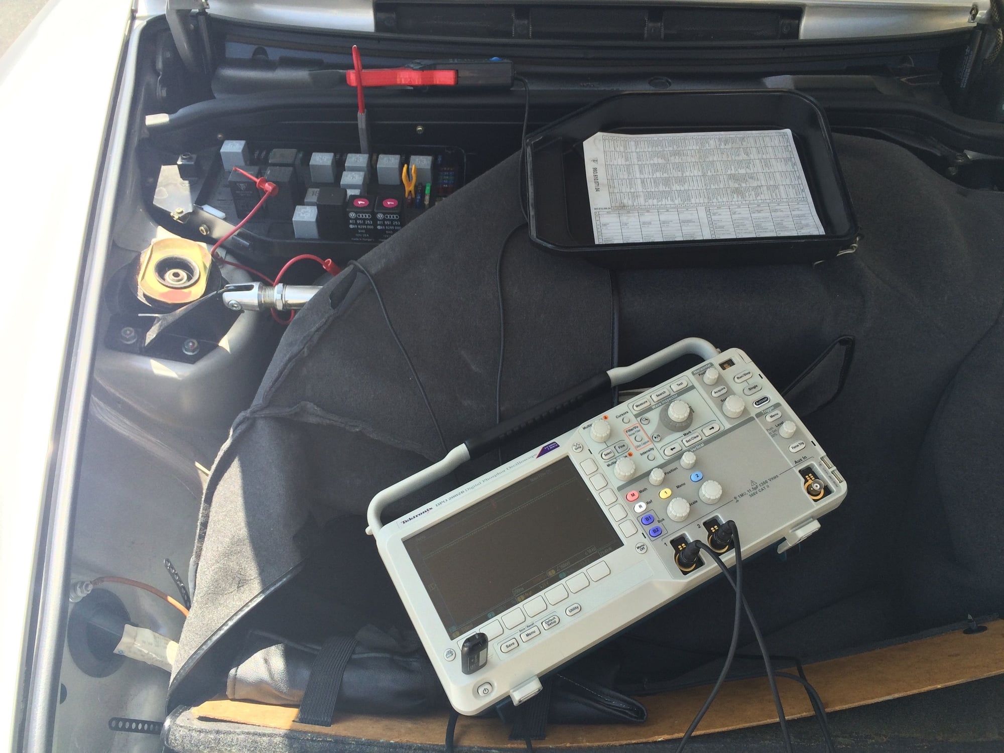
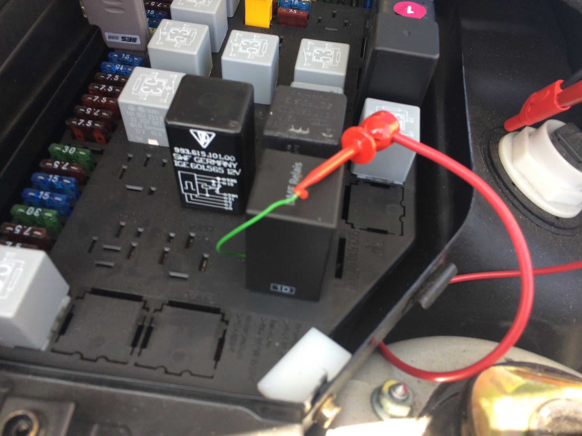
In this wide shot I have setup the scope and made the test point connections.
The current probe will be connected to channel 1 on the scope and the voltage
probe will be connected to channel 2.
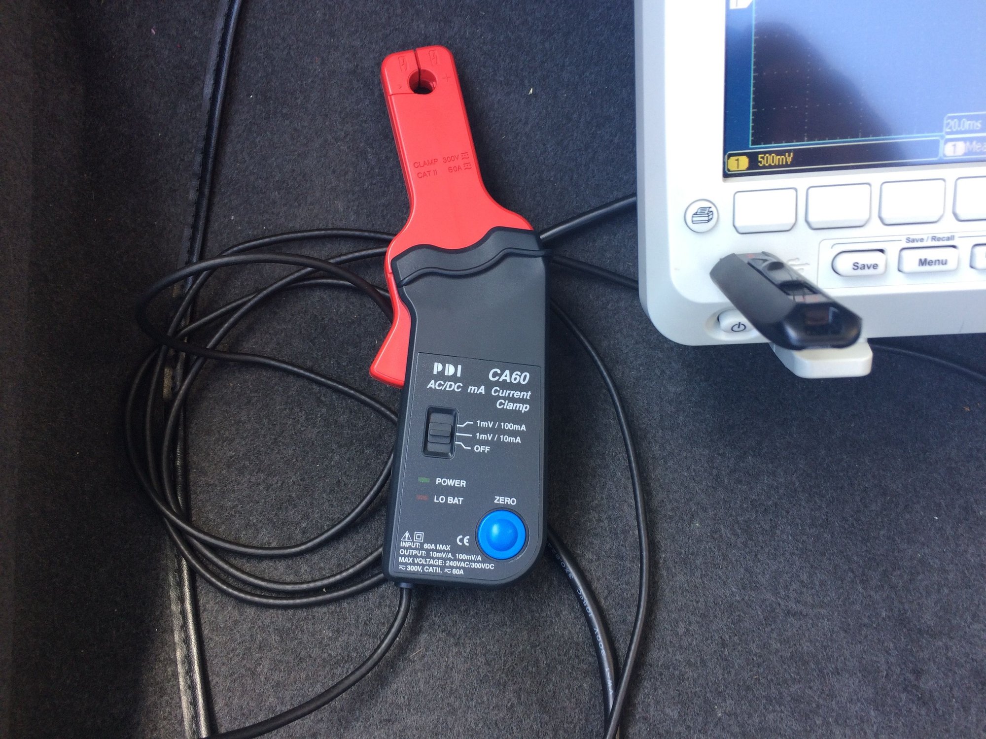
This is the current probe being used.
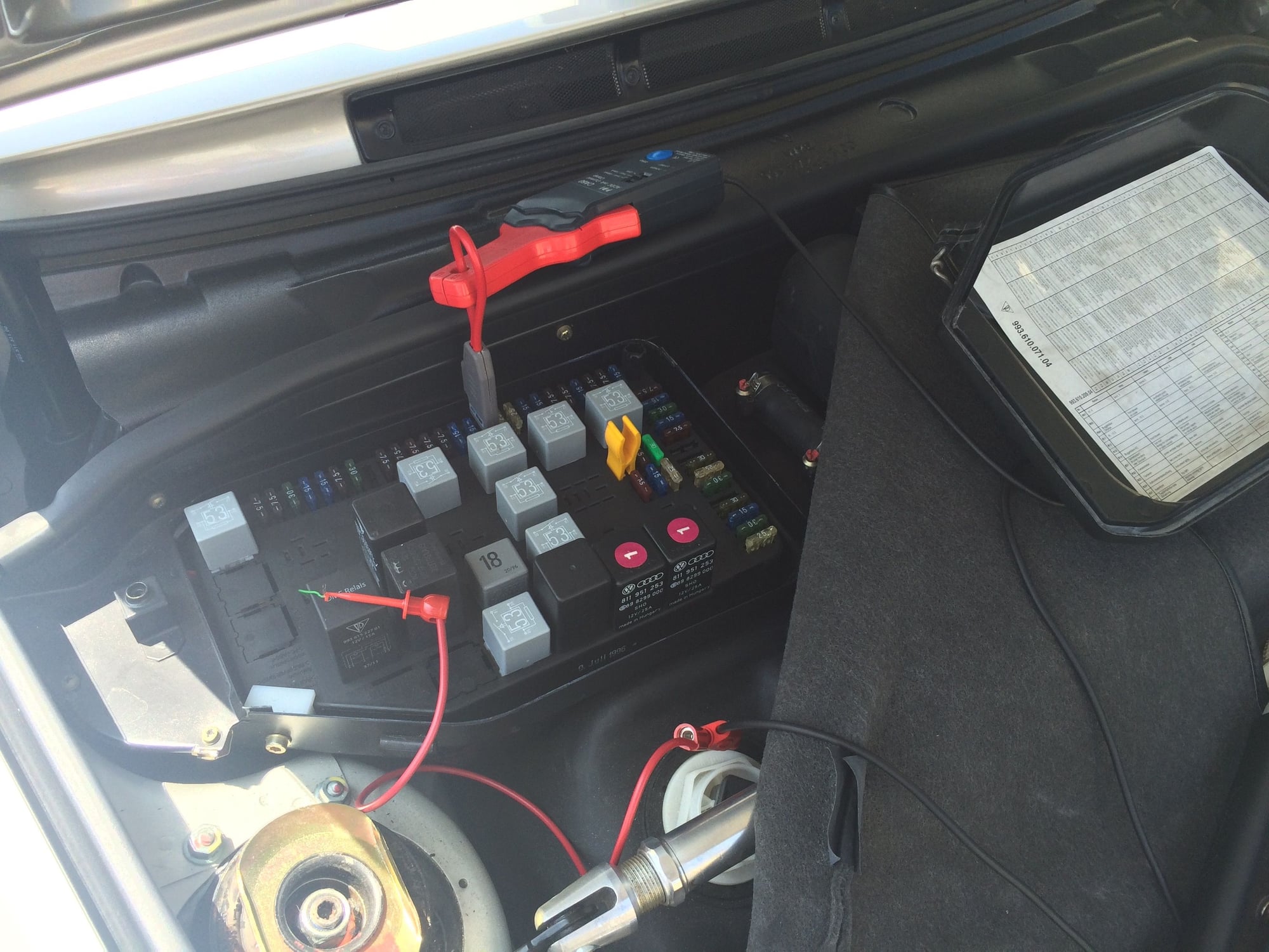
Here is a closer shot of the probe connections.
From the wiring diagram shown earlier, it can be seen that there is a fuse for the
fuel pump in the fuse panel. Fuse #26 is identified in the fuse box lid as the fuel pump fuse.
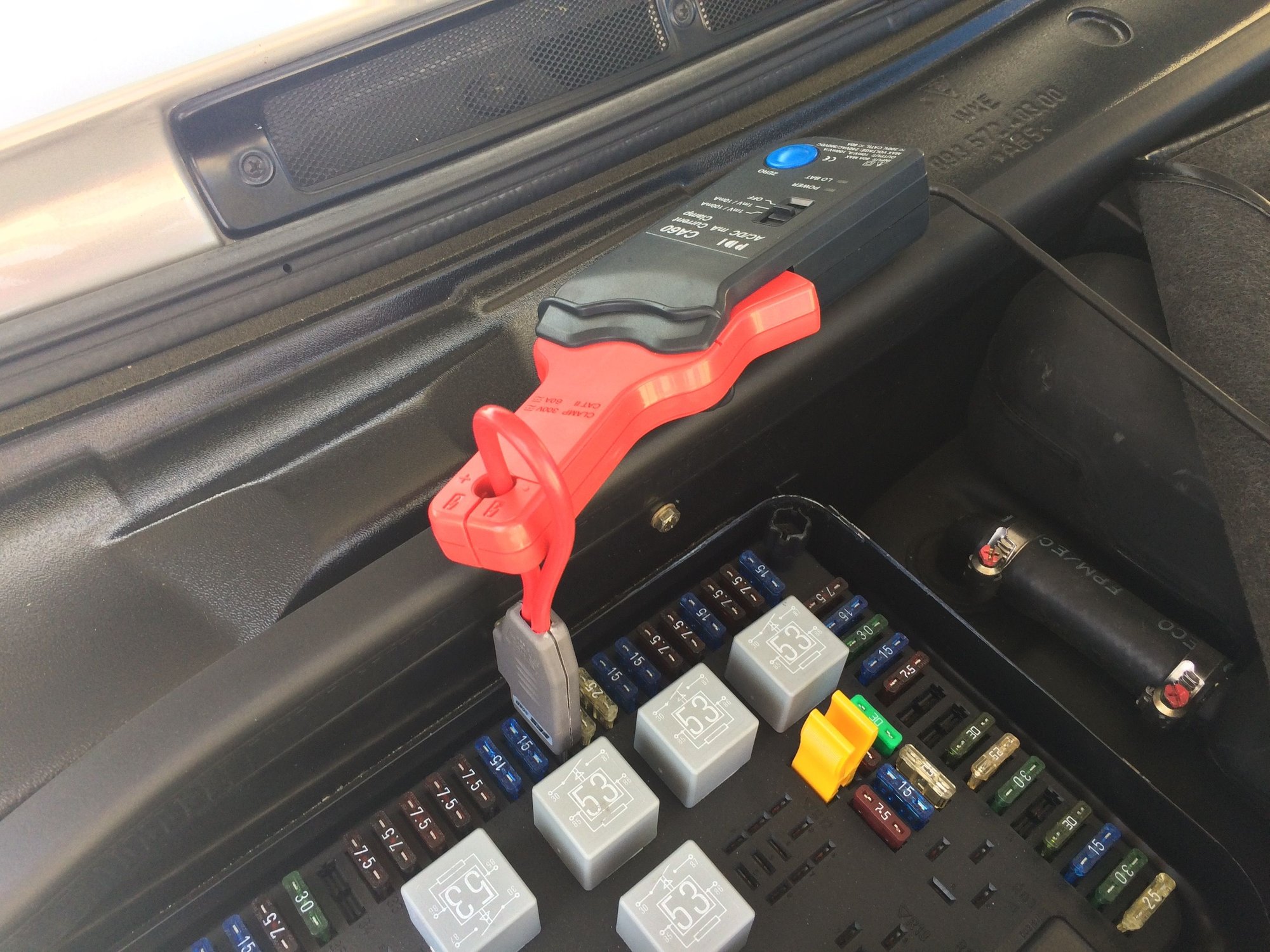
The Fuse Buddy 308BA current loop will be used to provide a way to connect the current probe.
Fuse #26 is removed and inserted into the current loop.
The current loop is then inserted into the fuse #26 position and the current
probe is attached. The current probe is turned on and set to the 1mV/10mA
setting and zeroed by pressing the blue button.
To probe the voltage going to the pump, we need to connect the positive end of
the probe to the terminal 87b of the DME relay and the negative end of the probe
to the the battery negative terminal.
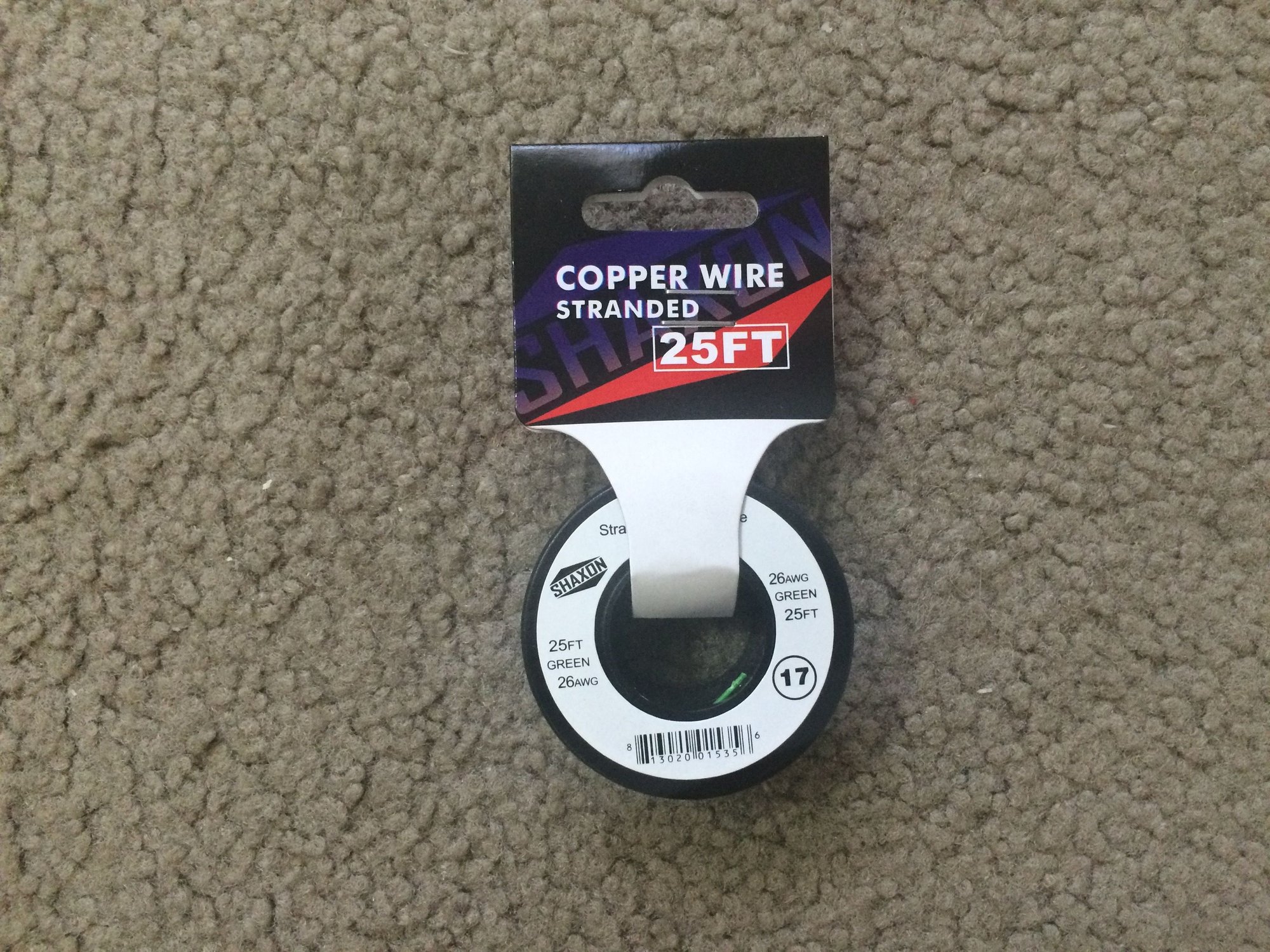
The trick here is to use a kluge wire. Pull out the DME relay and slip a thin piece
of wire down into the 87b terminal slot and then push the DME relay back in. I
used 26 AWG stranded copper wire for the kluge wire.
Here the positive end of the voltage probe has been connected to the kluge wire
after the DME relay has been seated.
Fuel Pump Tests and Results
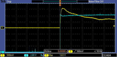
Inrush Current and Pump Voltage
In the above image can be seen a capture of the fuel pump current and voltage
at startup. Channel 1 (Yellow) is current and Channel 2 (Blue) is voltage.
The Channel 1 vertical scale is set to 500 mV per division and the zero voltage
point is mid screen. The timebase is 20 ms per horizontal division. I setup an
automatic measurement for peak voltage. This will give the peak inrush current.
A trigger was set on on Channel 1 for a rising edge of 160 mV.
The Channel 2 vertical scale is set to 2 V per division and the zero voltage point is
at the bottom of the screen.
To perform the test, trigger acquisition is enabled by pressing the “Single” button
and the car is started.
From the image we can see the results: Inrush current peaks at 16.3 A about
5 ms after start and then gradually declines to the operating current which will be
shown on the next capture. The inrush voltage initially peaks at startup at about
12.5 V and then drops to about 10 V coinciding with the current peak at about
5 ms after start. Voltage then gradually increases to the operating value which will
be shown on the next capture.
This is a good waveform. Significantly larger or lower current or voltage
measurements would indicate some sort of problem that would need to be
examined.
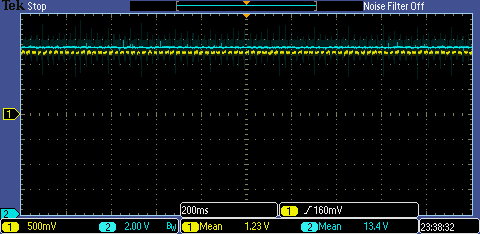
Operating Current and Pump Voltage
In the above image can be seen a capture of the fuel pump operating current
and voltage taken a few minutes after startup. From the wiring diagram it can
be seen that the oxygen sensor heaters are downstream of the probe connection
so waiting a few minutes to allow them to turn off is necessary to prevent a false
measurement.
An automatic measurement was added to each channel to calculate a mean
value for the current and voltage.
From the image we can see the results: Operating current is 12.3 A and
voltage is 13.4 V.
This is a good waveform. Significant larger or lower current or voltage would
indicate some sort of problem that would need to be examined.
Pump RPM
In order to calculate the fuel pump rpm, we need to determine how long it
takes for the pump to make one rotation. The current waveform will show a
hump for each commutator segment in the pump. If we know how many
commutator segments there are we can then calculate the rpm.
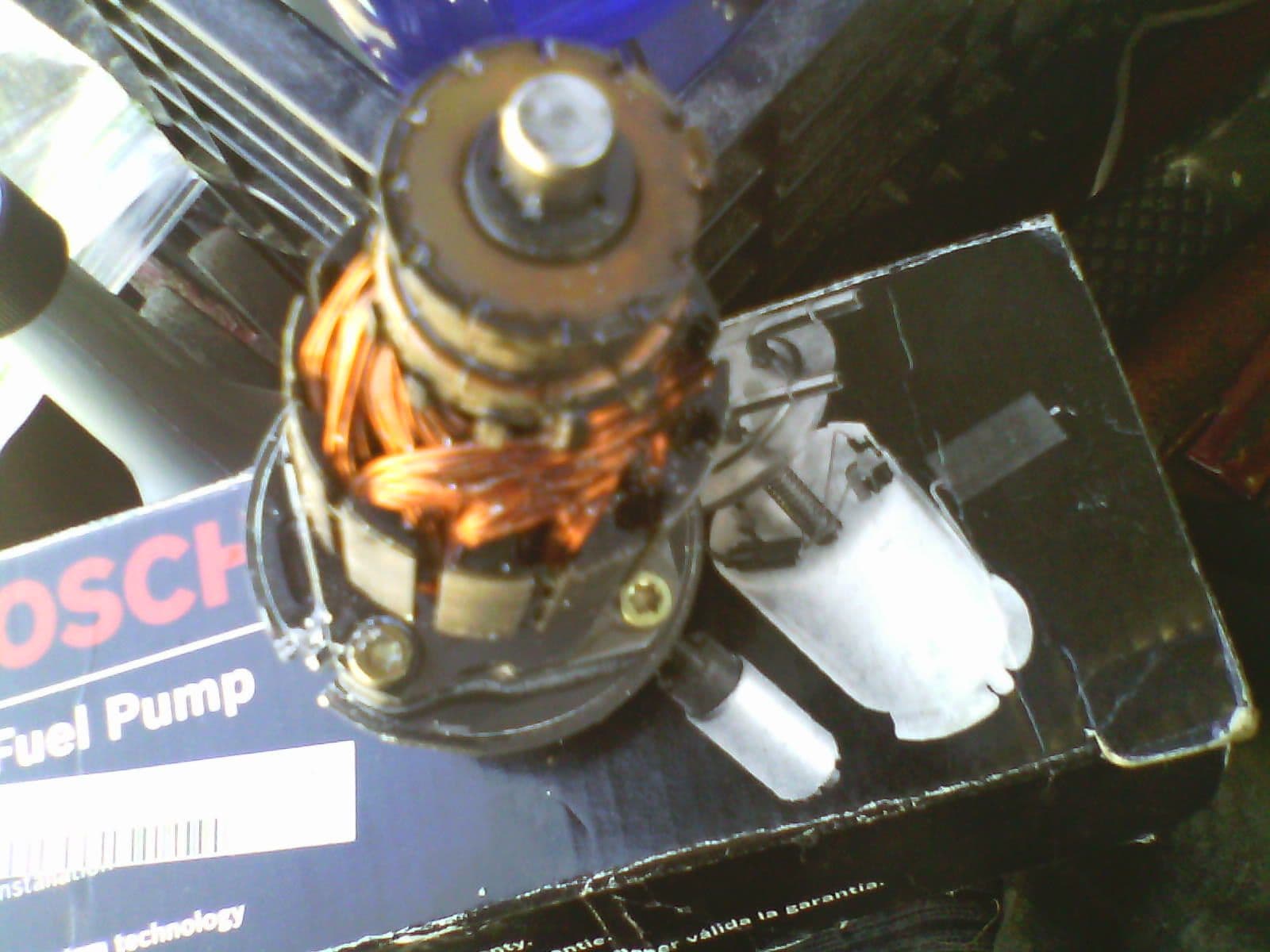
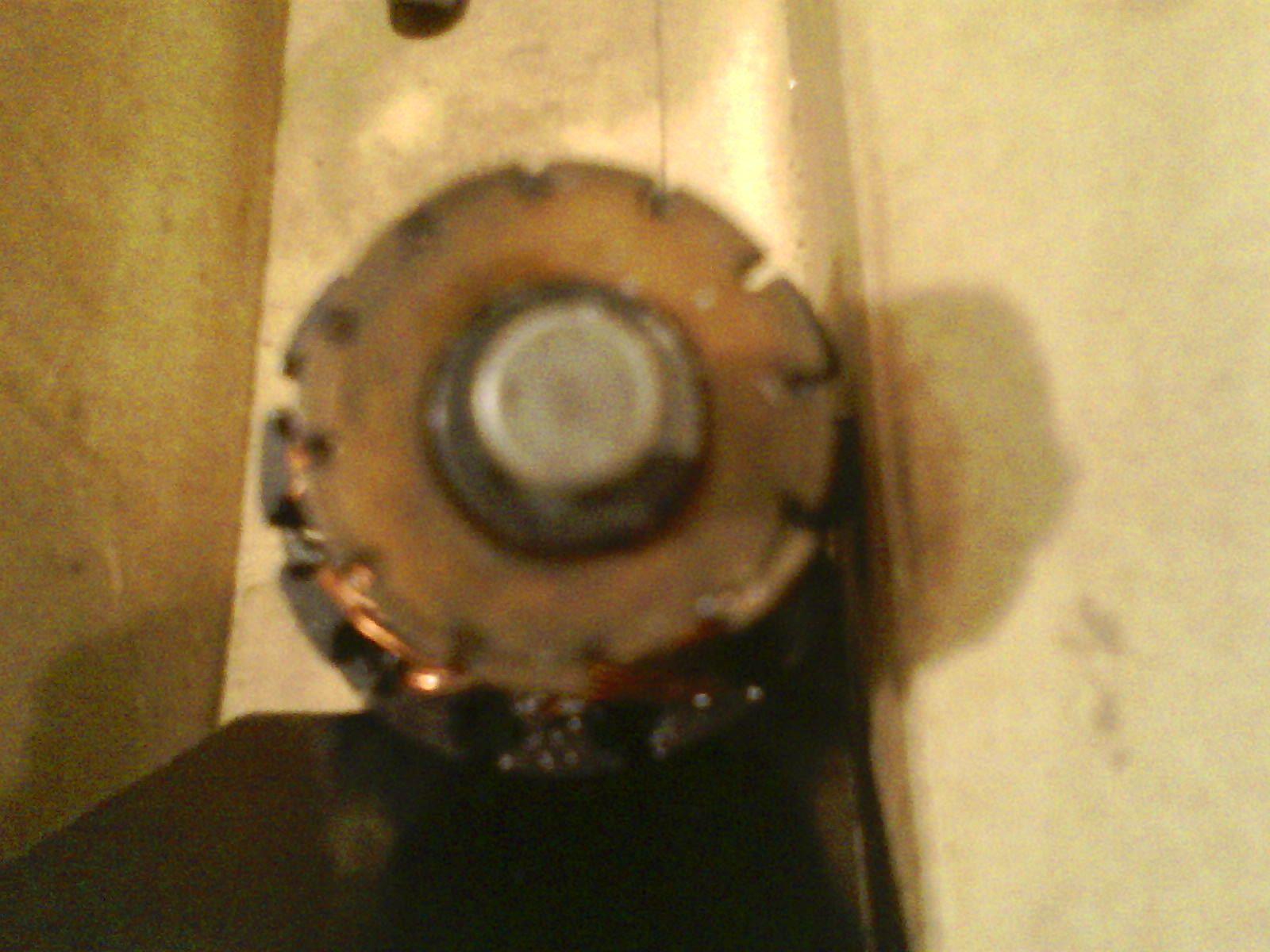
In this next picture is shown a fuel pump that failed in a 993 provided by TJ993.
Here is a closeup TJ993 provided of the commutator. There can be seen 12 commutator segments.
This configuration has been used by Porsche and Bosch for some time as shown
in this fuel pump from a 928 which also has 12 commutator segments.
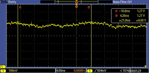
In the next image, a capture of the fuel pump current is shown in which the
individual current humps can be seen for each commutator segment as the
pump rotates.
I’ve placed cursors on the waveform to aid in calculating the time for one
rotation. Cursor “a” is placed on a current peak and then counting over 12
more peaks cursor “b” is placed. The scope displays the delta between the
two time markers as 21 ms.
We know that 1 minute = 60 seconds = 60,000 ms.
The RPM is then 60000/21 = 2857.
This appears to be a good number, insofar as no other abnormality in testing
has been detected.
Again, as far as assessing the fuel pump condition, any measurement that differs significantly from this would invite further inquiry.
Using the Test Points at the Fuel Pump
Disclaimer: I have not tested directly at the fuel pump. I don’t have a lift or a
place to put the car up on jack stands to try this out and write about it first hand.
Instead, I’m going to rely upon a Rennlist thread on fuel pump replacement and
repost a couple of his pictures to give the gist of the access issues.
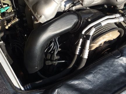
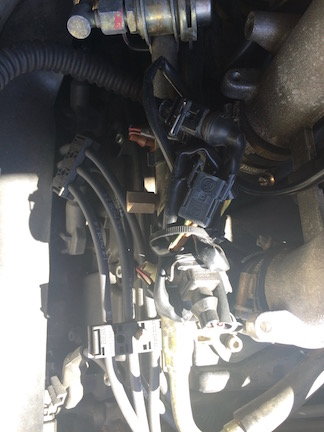
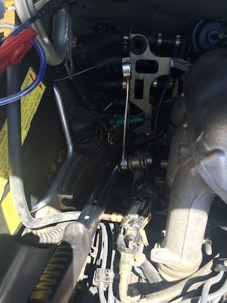
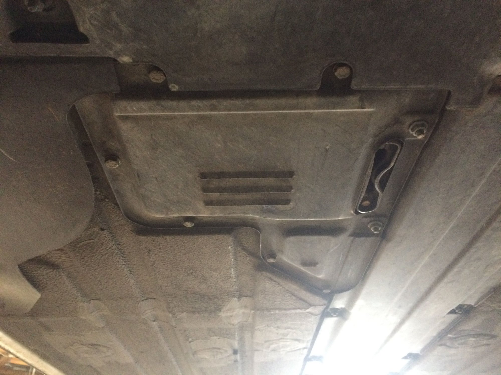
To access the wiring connections on the fuel pump, an access panel underneath
the car has to be removed.
(Inserting this shot taken during my latest oil change 5-29-2016)
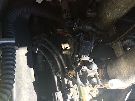
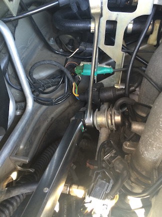
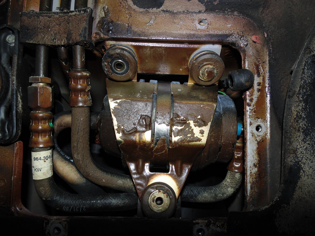
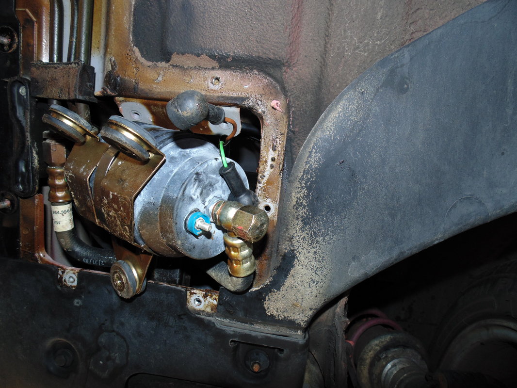
The fuel pump and bracket can now be seen.
In this photo the fuel pump has been maneuvered so that access to the wiring connections can be made.
From here on the test procedures are similar as described earlier, except that
now the current probe is clamped around the power side wire and the voltage
probe is attached to the power side connector and to the battery negative
terminal.
Voltage drop testing can now be done on the pump power side and the ground
side.
On the power side, connect a voltmeter to the fuel pump power connector and
to the battery positive terminal and measure the voltage drop with the pump
running. Should be around 0.5 V.
On the ground side, connect a voltmeter to the fuel pump ground connector
and the battery negative terminal and measure the voltage drop with the pump
running. Should be around 0.1 V or less.
Next up will be testing the DME relay and fuel injector testing.
Last edited by bruce7; 06-06-2016 at 04:48 PM.
Reason: added fuel pump access panel photo
 03-27-2016, 02:19 AM