When you click on links to various merchants on this site and make a purchase, this can result in this site earning a commission. Affiliate programs and affiliations include, but are not limited to, the eBay Partner Network.
Kerosene
compressed air
Molykote-55 O-ring lube for valve cover gaskets
Lubri-Moly Copper anti-sieze paste for spark plugs and external fastener lubrication
box of nitrile gloves (you will use a lot on this job)
Special tools needed will be:
Torque wrenches. A small one for the rocker arm and valve cover screws.
A medium size one for the spark plugs. And a large one for the wheel bolts.
I used a combination of Hazet and Stahlwille wrenches as I am in the midst of
migrating from Hazet to Stahlwille. Insert tool capability is highly recommended.
It is quite easy to round out a valve cover screw and it seems that grinding the
head off is the best solution. So I would have on hand a few grinding stone
options for use with a Dremel tool. Of the 38 screws, I had to grind one off on this job.
There are a fair number of subtasks that must be done to complete this job.
Initially I�m going to cover the core task and later add some more into and
pictures for the subtasks such as the mufflers, tips and engine tin.
The DIY is attached and a photo album can be found here:
These write ups are very much appreciated - but how can I tell which photo corresponds to each step in the written document? Why not post the text and images together in the thread, or even in the PDF document?
Bruce- I would like to attempt this diy but a few steps were a bit muddy to me. So how do you position TDC for #1 with the red mark as pictured? Then how do you rotate engine 120 degrees? If I understand it correctly, when you proceed to the next rocker, you rotate the engine?
These write ups are very much appreciated - but how can I tell which photo corresponds to each step in the written document? Why not post the text and images together in the thread, or even in the PDF document?
Hi, thanks for the questions. Let's see if I can explain it so it makes sense.
I'd like it if I could get a photo to correspond to every step but it can be
difficult to do. Ideally I would have someone shoot over my shoulder and
get coverage of all the steps with good lighting and focus. In reality, I work
on the car alone and sometimes it is very hard to get a good photo using my
phone camera.
So in the photo album there will be pictures that are usually arranged in sequence
to match the DIY, but some steps may not have a corresponding photo.
The format that I have used is to write a terse DIY so as to keep it brief and
to the point. The point being the main core task, such as the changing of the
valve lifters, with the subtasks as brief bullet items which can be looked up
if necessary. The alternative would be a very long document if every detail were
to be included.
A more ideal format would be to use a website posting, such as a blog,
and each step in the DIY would be link to a page where the details and
photos for that step are presented. But for now, I'm using this forum
and working within the limitations of the medium.
About your question about combining text and image together in the forum,
my thought is that it doesn't work. It can work if there are only a few
photos, but for more than 6 it becomes clumsy and unwieldy. It also
doesn't support updating very well as a thread is a linear process that
grows by appending. The Google cloud has a much better user interface
for photo albums than the forum and that makes it a better choice.
Including images in a PDF makes the PDF very large and by necessity
lowers the resolution of the images. Also making PDFs look good with
text and images requires some software I don't have and don't really
want to acquire.
By freely distributing the images on Google, I have enabled you to copy
the images, modify them, and use them in any way that you want. I think
this is better.
Bruce- I would like to attempt this diy but a few steps were a bit muddy to me. So how do you position TDC for #1 with the red mark as pictured? Then how do you rotate engine 120 degrees? If I understand it correctly, when you proceed to the next rocker, you rotate the engine?
OK, I may have left something out. With the spark plugs out it will be very
easy to rotate the engine using the alternator nut and a 24mm box-end wrench.
Rotate the engine until the red mark (TDC) aligns with the case mark. Now
open up the distributor cap for the top distributor. Lift up the cap just enough
to see if the rotor is pointing at cylinder #1. You might want to unplug the
coil wire to make this easier. The rotor will be pointing at either #1 or #4.
If it is pointing at #1 you can now start on changing #1 valve lifters. If it is
pointing to #4, rotate the engine again until the red mark lines up with the case
mark and check the rotor. It should now be pointing at #1 cylinder.
Now, there are 3 notches on the pulley. They are 120 degrees apart. To get the
next cylinder to TDC, rotate the engine until the next notch aligns with the case
mark. Now you should be working on #6 cylinder.
Ok, understood. Thanks for the explanation. Last questions for the night, lol. Are there rockers/lifters in the upper banks or just the lower banks of valve covers? Then 2 lifters per rocker assembly or just one? I've done VC gaskets before and would like to attempt this "while yer there". TIA.
Ok, understood. Thanks for the explanation. Last questions for the night, lol. Are there rockers/lifters in the upper banks or just the lower banks of valve covers? Then 2 lifters per rocker assembly or just one? I've done VC gaskets before and would like to attempt this "while yer there". TIA.
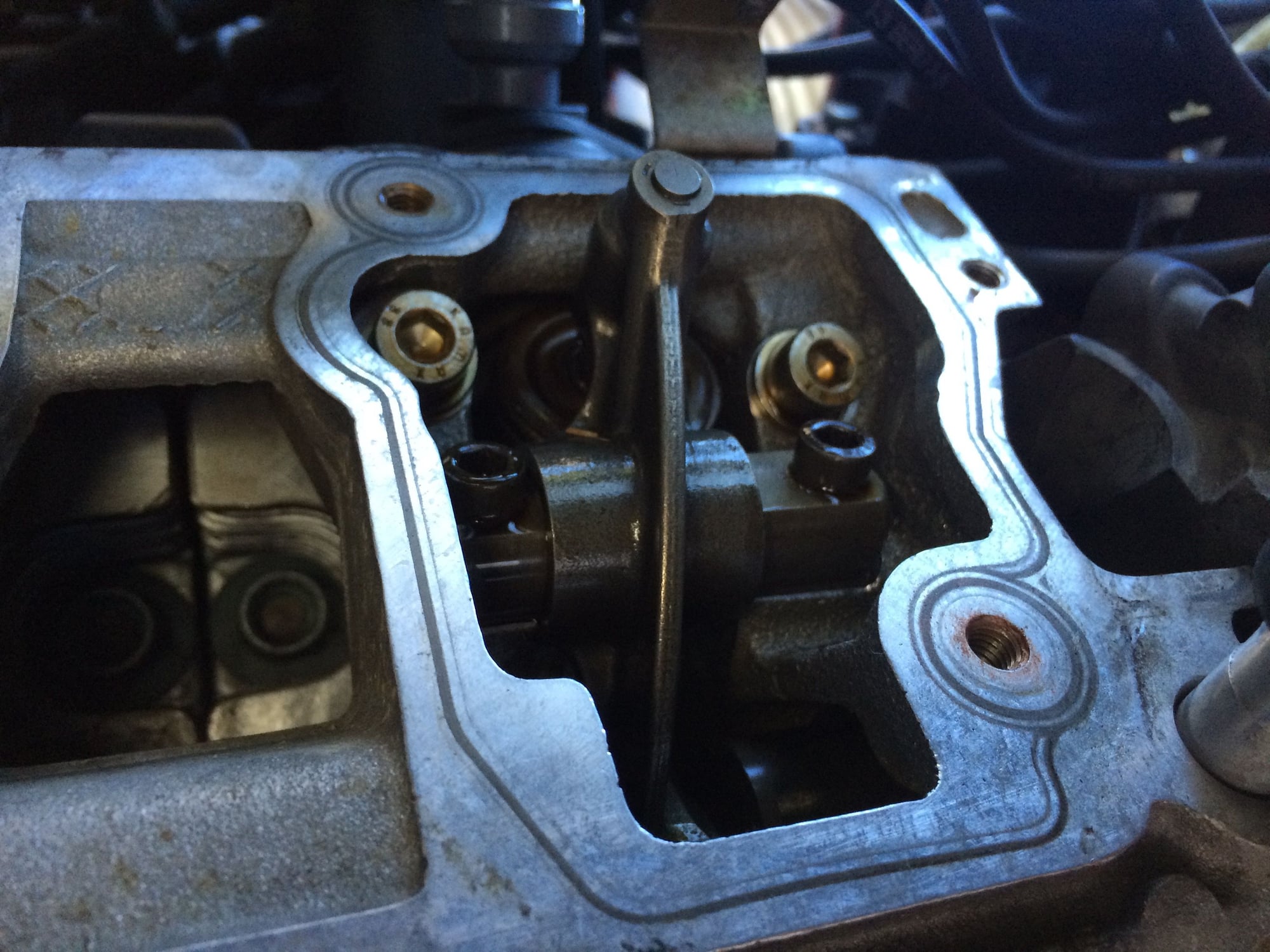
Yes, there are lifters in the upper and lower banks. In the upper are the intake
valves and lifters and in the lower are the exhaust valves and lifters. There is
just one lifter for each rocker arm. A good high-level guide to understanding the valve
train is contained in this document: http://www.pcarworkshop.com/images/a...r_-_geolab.pdf
Bruce- your knowledge and guidance is much appreciated. Thank you kind sir
Originally Posted by bruce7
Yes, there are lifters in the upper and lower banks. In the upper are the intake
valves and lifters and in the lower are the exhaust valves and lifters. There is
just one lifter for each rocker arm. A good high-level guide to understanding the valve
train is contained in this document: http://www.pcarworkshop.com/images/a...r_-_geolab.pdf
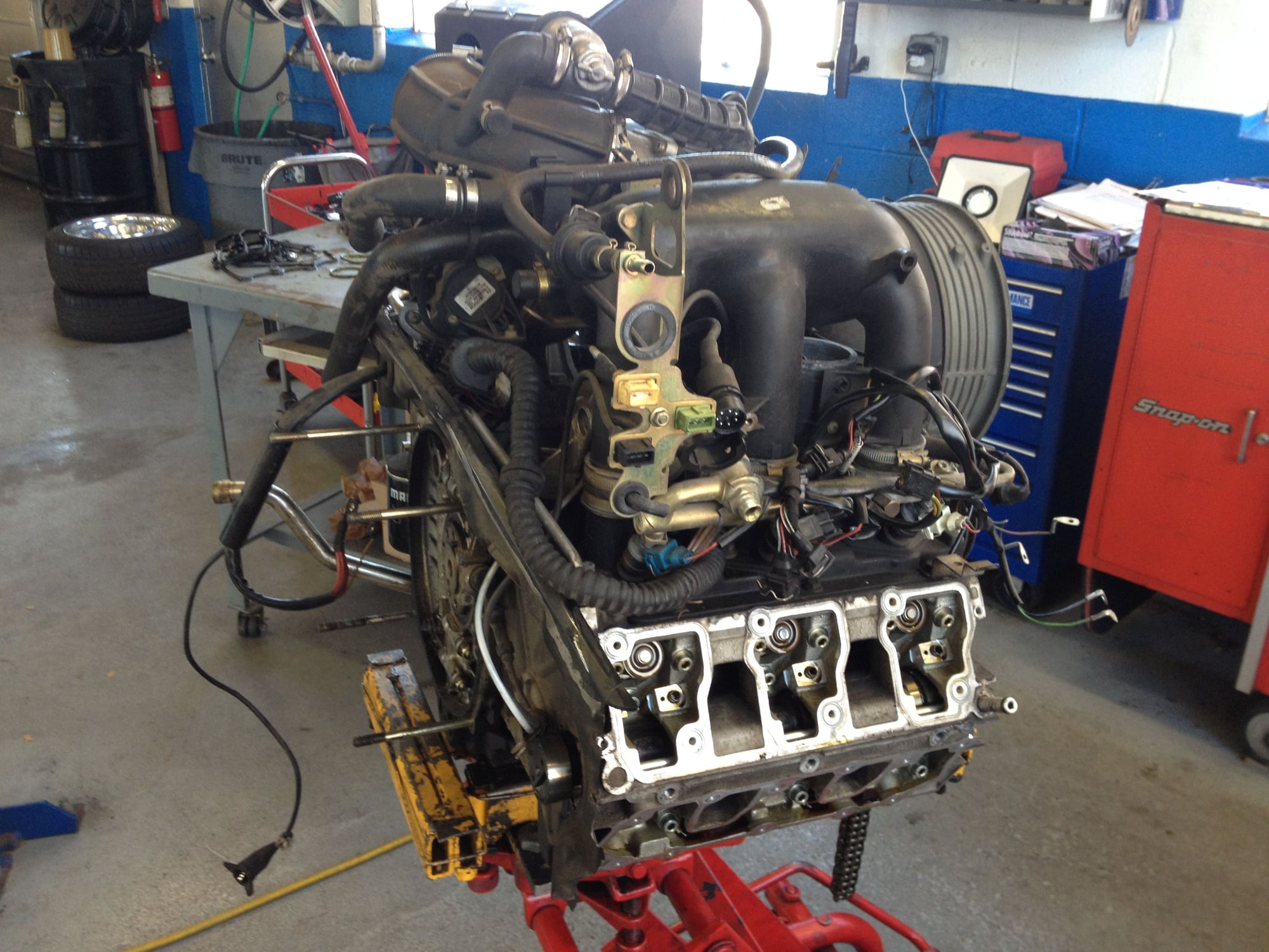
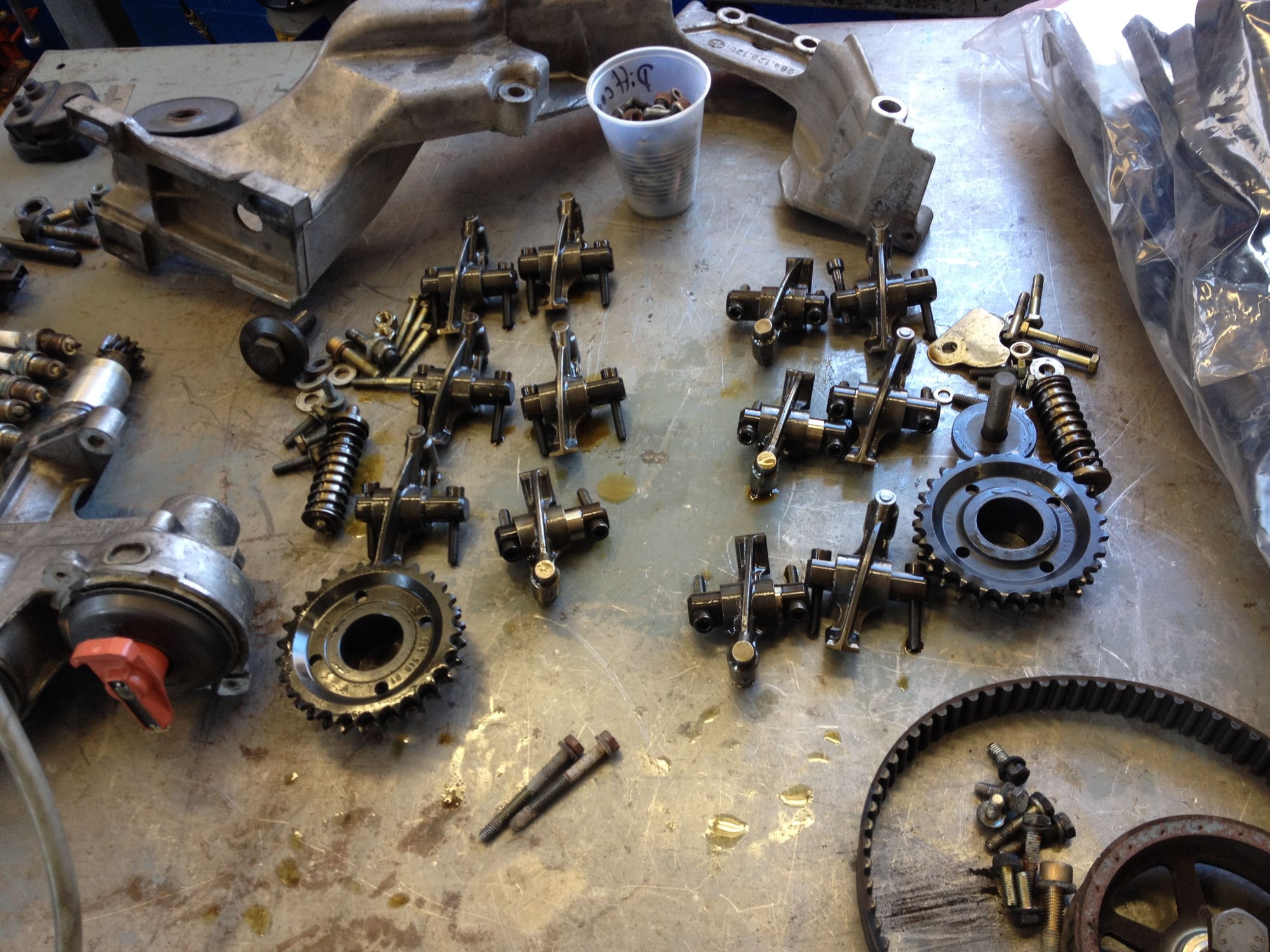
Another great DIY thread, thanks Bruce. I recently dropped the engine in my C4 and replaced all the lifters. Here are a few shots of the engine with all of the rocker arms removed.
What was your source for the lifters? What about the posts alluding to two different sizes out there - some being taller or something? Did you find anything about that. You didn't happen to measure the dimensions of one of yours before installing did you?
Interesting tip about soaking overnight in oil. Did that help with the startup chatter? How many minutes of chatter did you suffer, if any after soaking them. What is that chatter btw it sounds terrible.
Nice work on torqueing that combination screw under the ps pump. When I did my upper covers I looked at that and thought 'Well, no one is getting a tw on that one' lol. Wrong! What I did was incrementally just follow my pattern and that one just got the same degree swing as the others with a regular rachet and when they start clicking it just got the same final swing they did. Nice work.
From what I recall, I believe the "oversized" (as opposed to "standard") are to take up slight slack from wear. Not sure if it's the pocket of rocker arm or (most likely) the valve stem. Just wanted clarification. If it is an issue. And yes, Bruce has given back, ten fold, in the last few days.
Aloha
On the question about different valve lifter sizes, I found a couple of posts
where Steve W. at Rennsport Systems speaks to this issue:
 02-20-2015, 09:18 PM