When you click on links to various merchants on this site and make a purchase, this can result in this site earning a commission. Affiliate programs and affiliations include, but are not limited to, the eBay Partner Network.
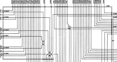
I'm chasing down a battery drain problem and have come across some notation I'm not familiar with (see pic). One is the little square box with a number in it. There are 3 in the pic. The second is the double line that orbits around seemingly gathering up some of these signals. Anyone know what these signify?
Welded or soldered joints, embedded in the wiring harness. There is no information on where exactly these are placed.
This has been discussed previously here on the board, either 964 or 993 forum. I can't find the thread right now.
Cheers,
Tore
Thanks for all the responses, yet there seems to be some confusion as to the notation used by Porsche.
Anyone know of a document that describes these symbols?
Lacking that, for future reference, I'll summarize what I believe to be true.
1. The square symbols refer to joints created in the wiring harness.
2. As far as I can tell, these joints are not necessarily connected to a grounding terminal. Grounding terminals are denoted by MP and a roman numeral. I did find joints that were grounded though.
3. The double lines indicate signals wires that are bundled together. The bundles are labeled. For example, the bundle containing joints 1, 2 and 3 in the diagram above are in bundle N0.180 (as far as my eyes can tell).
4. I do not believe the joints are in common with other similarly numbered joints on other pages. I say this because I tracked joint "1" to several other pages in which the wires connected together by "1" were shown to be in different bundles. For example, the "1" joint at G9 in the drawings is in a bundle labeled N0.2/60. Not knowing what the label means, I would guess the joints aren't the same.
I will gladly edit my summary if someone provides more substantive input, especially with regard to statement #4.

 07-28-2016, 12:37 PM