When you click on links to various merchants on this site and make a purchase, this can result in this site earning a commission. Affiliate programs and affiliations include, but are not limited to, the eBay Partner Network.
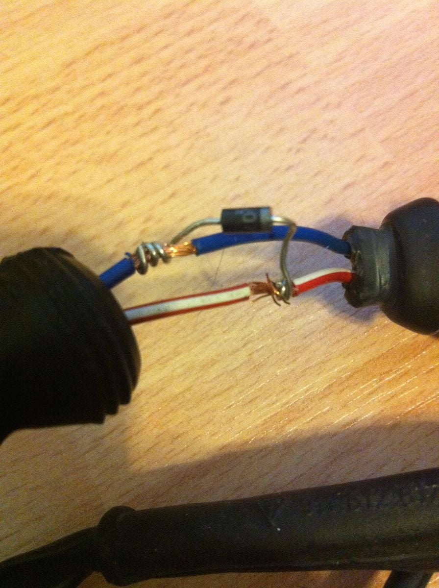
Btw this is a flyback diode, common to put across a dc motor or solenoid (anything with a coil winding) being controlled by pulse width modulation aka pwm. Without the diode the voltage spike reased from the coil when the pulse goes "low" can't go anywhere and instead of seeing 1 0 1 0 1 0 pulse the motor basically sees 1 1 1 1. The diode gives a path for the flyback voltage through the +12v (flyback >12v).
Thanks jstyer and alexjc4. With my intercooler installed, I could not get to the plug on the car to verify with a volt meter Will add the diode this weekend. For the other harnesses (O2 and coil packs), I am getting a proper tool for installing the waterproof connectors.
Thanks jstyer and alexjc4. With my intercooler installed, I could not get to the plug on the car to verify with a volt meter Will add the diode this weekend. For the other harnesses (O2 and coil packs), I am getting a proper tool for installing the waterproof connectors.
What sort of connectors/crimp tool are you going for?
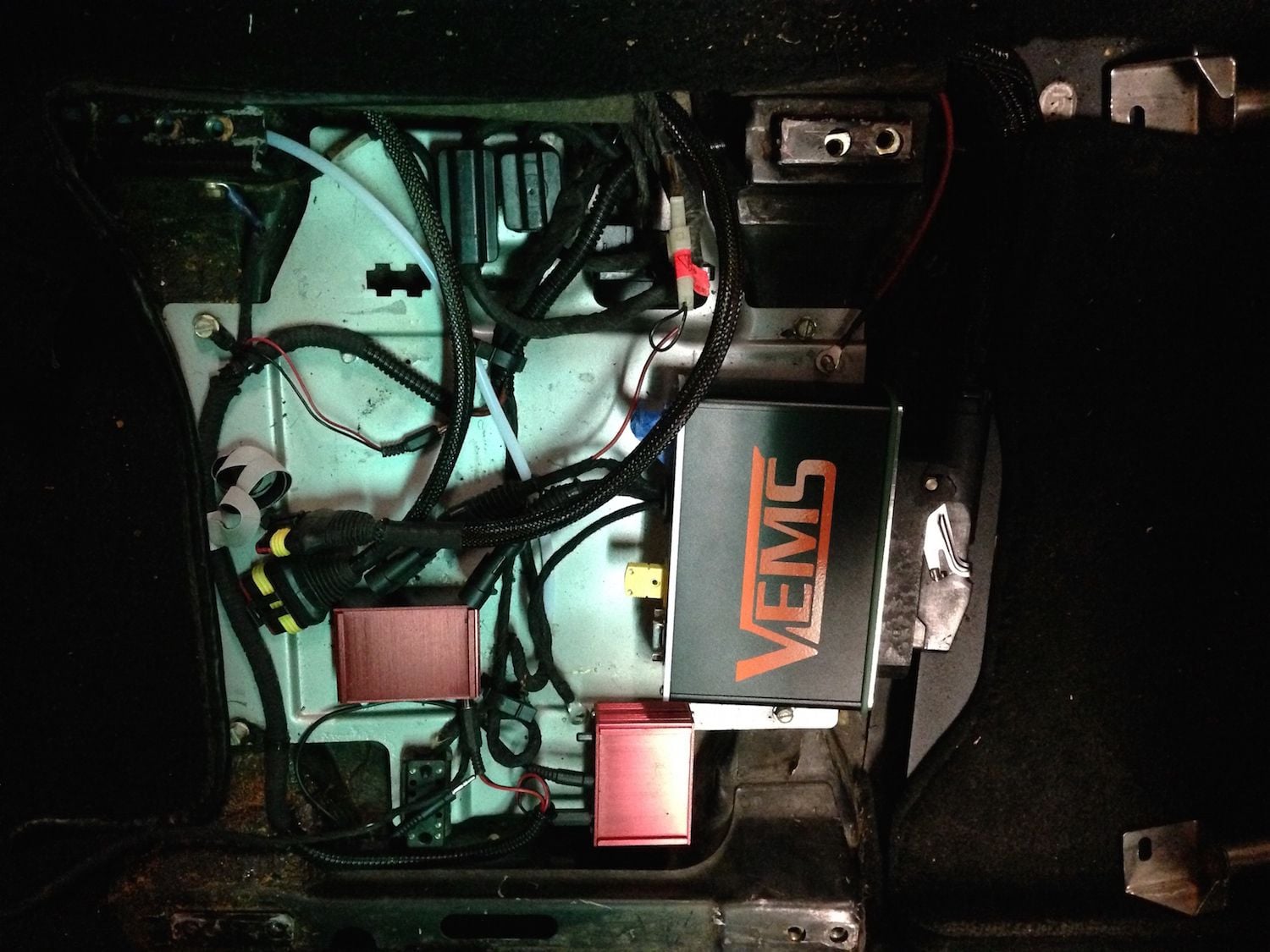
I'm thinking of putting this ISV flyback diode inside the VEMS case to make it neater. Peep isn't sure thsi will work but since the injector flyback diodes are all inside the ecu I don't see why not.
Since you have a loom there can you tell where the standard injectors +12v comes from? Does that come from a pin on the ECU or from elsewhere? Again I'm tempted to make this flyback connection inside the ECU if I can. I've not check this idea with Peep though.
I'm also thinking of taking the power for the o2 sensor heater from inside the ECU case. Just using the pin37 DME relay power input and an inline fuse in the case or maybe a panel mount fuse holder and cut a hole in the rear panel, to make that easy to check and change.
Unfortunately the home projects have taken up most of my time lately. We are finishing a room over the garage and I plan to insulate and wall in the garage. So I have had to keep the car running to move it around (also it has been beautiful the last few days, perfect for the convertible). Hooking up the VEMS requires me to disconnect the injectors right now and that is not an easy task with all the TPC parts. Will try again this weekend since we have an extra day.
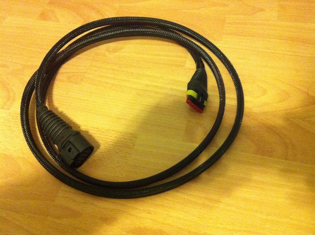
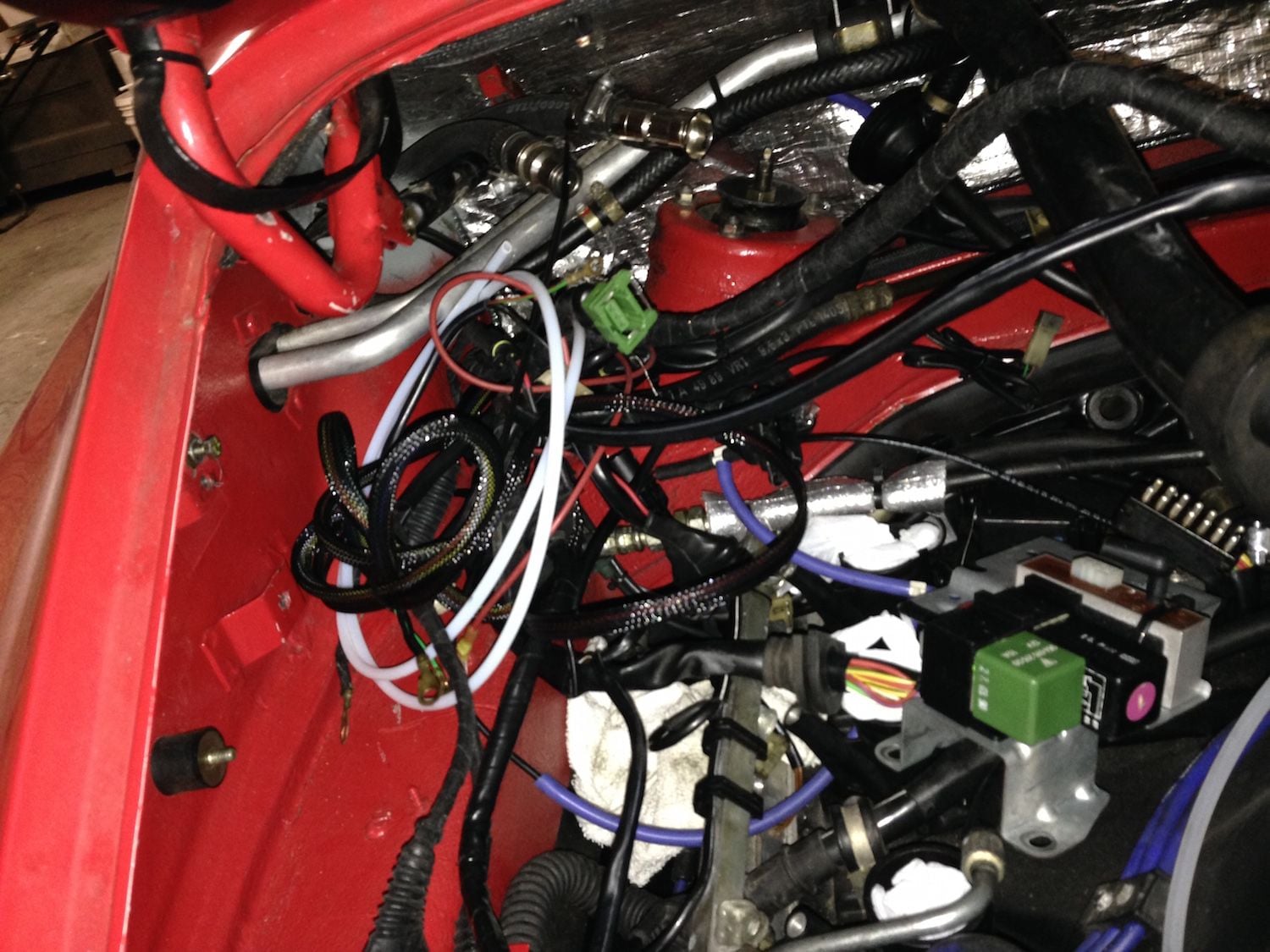
I did get the diode installed in the new wiring harness. Also I finished the wiring loom for the wideband O2. I still need to do the wiring loom for the 2 bosch coils which will be next.
Not moving as quick as I like due to a multitude of home projects. However I am working on wiring harness and trying to document everything. Following is my rendition of the wiring for the coil packs. Raceboy has been very patient with me as I put the wiring diagrams together - I have to see everything visually to make sure I do it correctly. I apologize that the below is not a true electrical schematic. I am a purchasing manager and did not follow in my father's foot steps as an electrical engineer.
I know the upper and lower plugs fire simultaneously and it looks like input pin 1 on the coilpack fires output pins 1 and 4, input 2 fires output 3 and 6,input 2 fires output 5 and 2, is that right?
So does VEMS have the firing order as:
E5+E6 (which fires cyl 1 and 4, one of which will be the "wasted spark" cyl)
E3+E4 (which fires cyl 6 and 3)
E1+E2 (which fires cyl 2 and 5)
repeat
Very hot and humid here right now, so all work is being done on extra wiring harness in the nice AC.
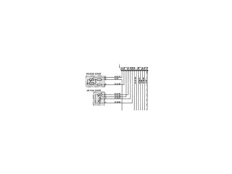
Most everything is done. Need to wire in the air intake temp sensor due to conversion away from the AFM. From the wiring diagram, I need to connect it between pins 1 and 4. Since pin 3 is the power from DME, was not sure if that is the power that needs to go through the sensor, however the attached information on the AFM says to check between pins 1 and 4.
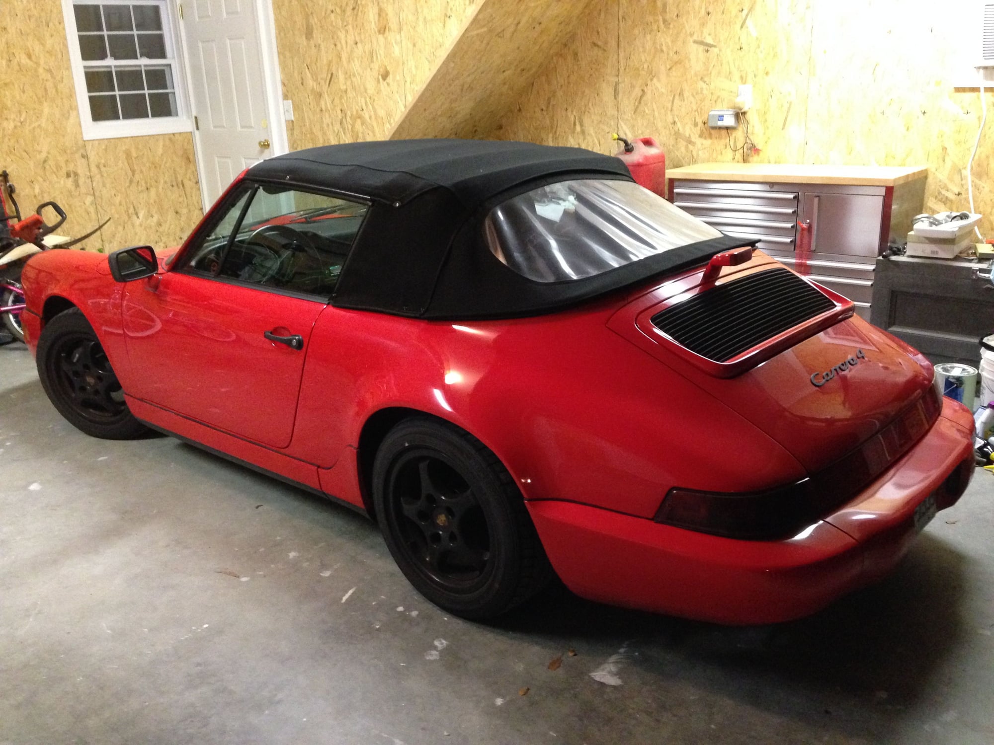
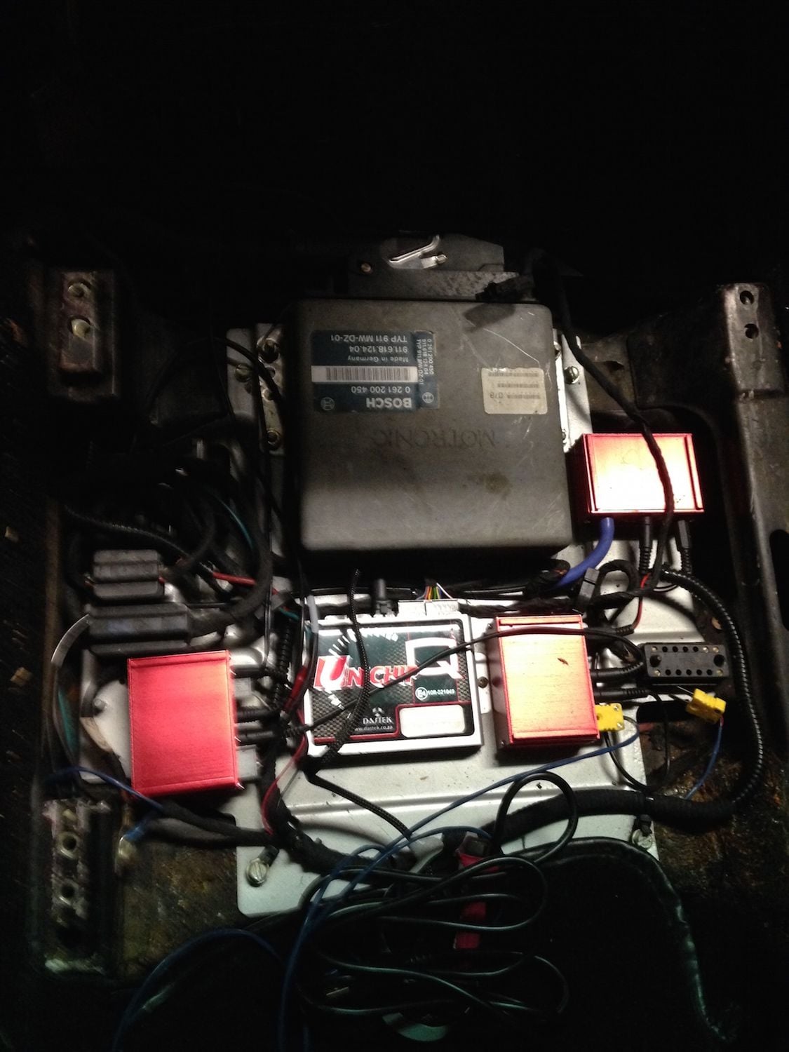
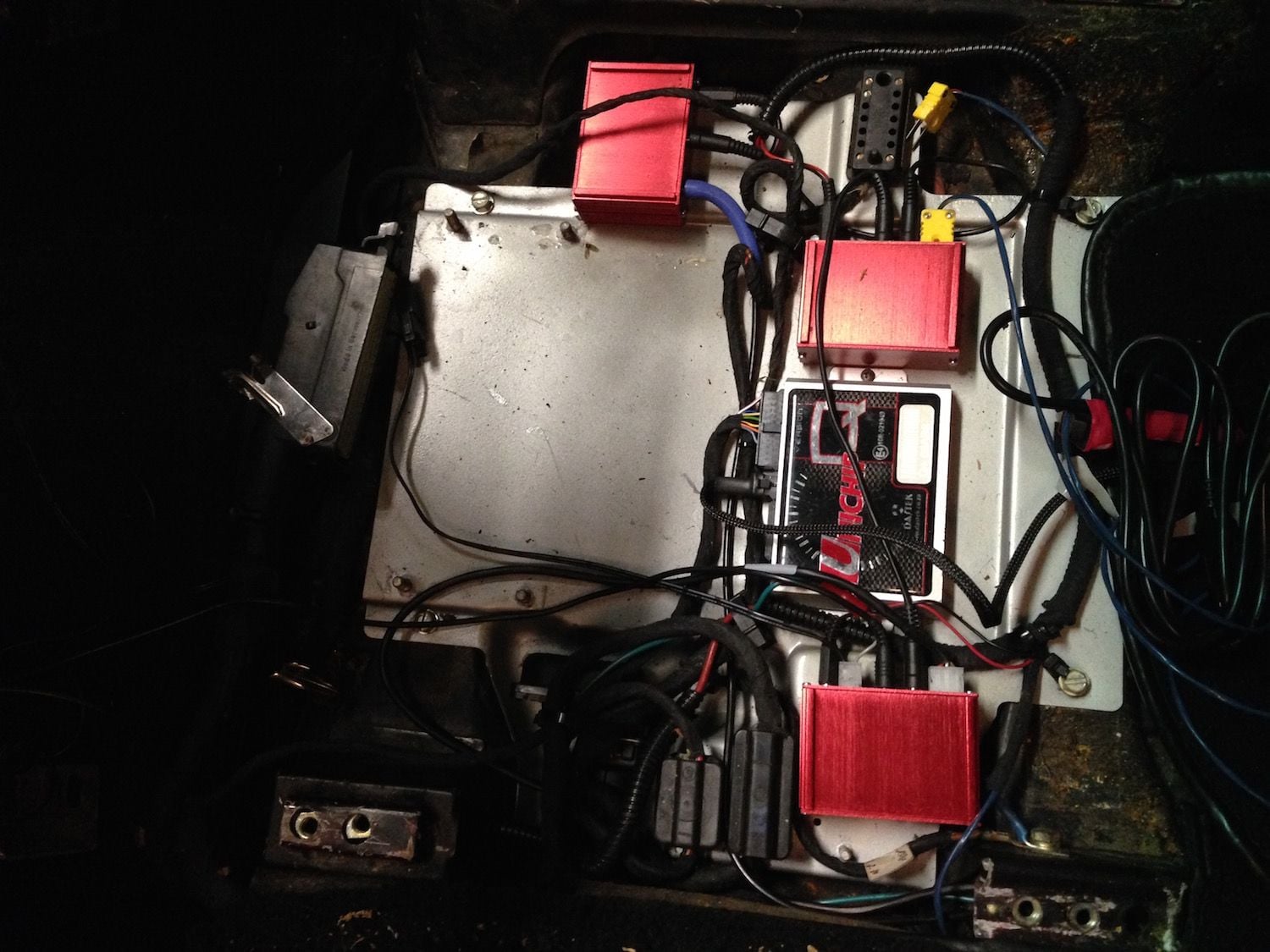
Finally the garage is pretty much remodeled and can start back on the VEMS install. I will start posting pictures later this week after more progress (so far only the driver seat is out to remove motronic, unichip, and some PLX boxes).
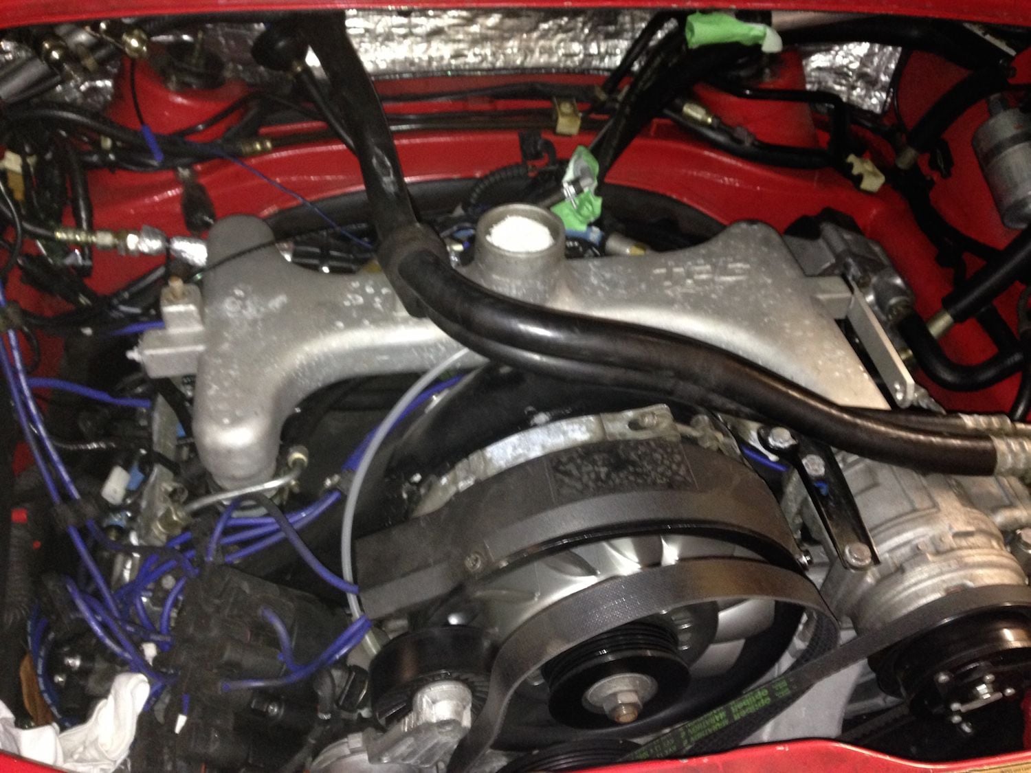
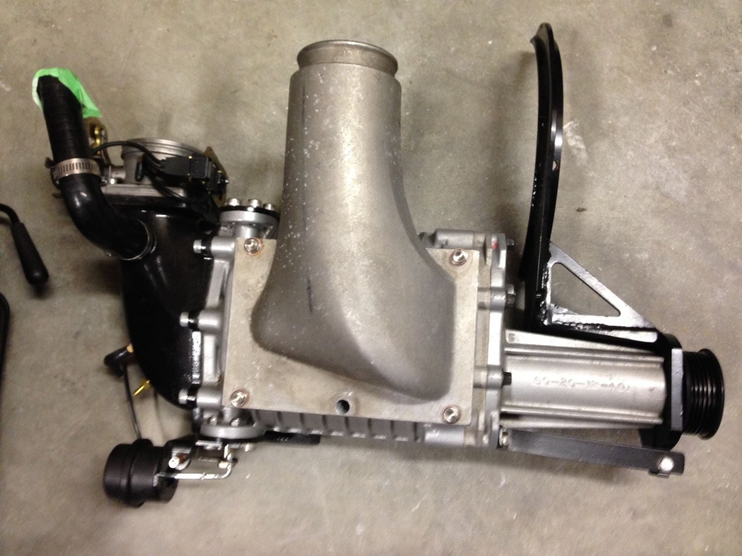
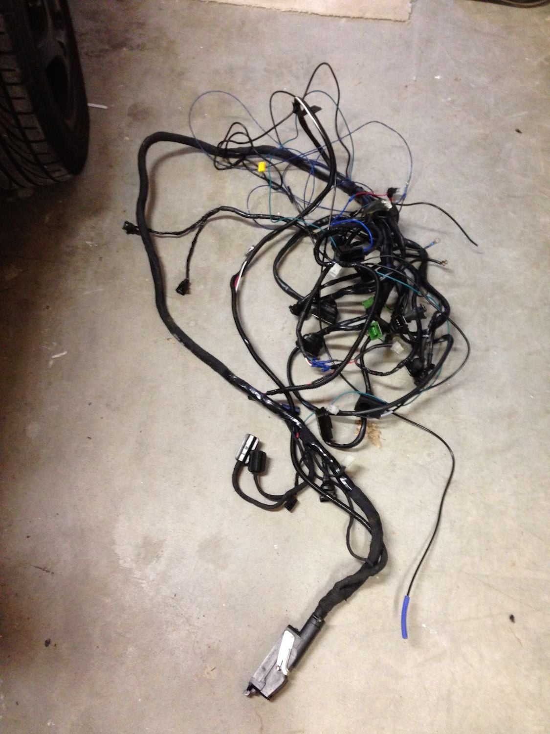
I have started dismantling everything in order to take out the old wire harness and change out the components. I noticed a large amount of oil in the intake even though I know my oil level has been good. I will plan to put a oil catch can coming from the oil tank to the intake. Here is what I need to do:
Finally the garage has enough room for me to park the car.
Bye bye old Motronic and Unichip
Took me a lot less time to take off the parts than to put them on.


 08-22-2014, 01:43 AM