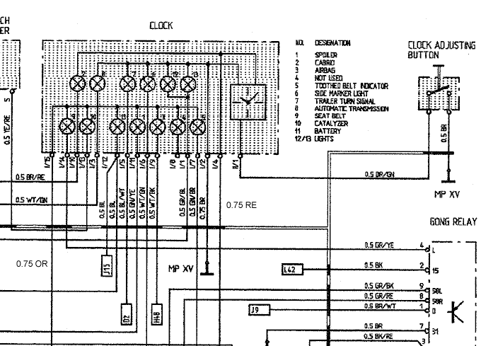
Clock Connector Wiring Diagram Help Please!
#1
Hi All
I had to make a repair on the clock connector which required taking the connector apart. I neglected to note where the 14 wires went to the 15 numbered pin holes in the connector. Can someone provide me a list of which colored wire goes to it's associated numbered pin hole in the connector?
Thanks in advance
Bill
90C2
#2
darth, go to www.porsche964.co.uk. There is a link there that I believe gives a pretty good explanation of the soldered connedtions behind the clock. It is covered in the topic about air bag and seat belt warning lights always on. Have you check in Adrian's 964 Enthusiastic Companion book.
#4
Don
Adrians book and the website you provided doesn't have what I need. I think Jason's diagram is what I'm looking for - problem is I can't read it - also I have 14 wires that came out of the 15 pin connector(i.e there was one blank pin hole). Either my monitor doesn't have the resolution or the diagram is blurry. Can someone verify the numbering on the top & bottom rows of pins from left to right and the color code associated with each pin?
This what I managed to read but I'm not sure if even these are correct. The ? are definitely unreadable.
Top Row of pins from left to right
2-BR/RE; ?-WT/GN; 7-BL/WT; ?-WT/GN; ?-G?/??; 13-G?/??
Bottom Row of pins fromleft to right
9-GR/YE; 10-WT/GN; 1?-BL; 1-B?/YE; ?-WT/??; ?-N/C; ?-G?/??
Thanks Again
Bill
90C2
#6
Instructor
Join Date: Jul 2005
Location: shropshire U.K
Posts: 232
Likes: 0
Received 0 Likes
on
0 Posts
2 BR/RE
8 WT/GN
7 BL/WT
6 WT/GN
12 GR/BR
13 GR/BL
9 GR/YE
10 YE/RE
11 BL
1 GN/YE
3 WT/BK
4-----
5 GN/BR
this is the best i can make out cus my diagram looks to be from the same source
8 WT/GN
7 BL/WT
6 WT/GN
12 GR/BR
13 GR/BL
9 GR/YE
10 YE/RE
11 BL
1 GN/YE
3 WT/BK
4-----
5 GN/BR
this is the best i can make out cus my diagram looks to be from the same source

#7
Rennlist Member
from left to right on the diagram
pin 15 0.75 OR, pin 14 0.5 GR/YE, pin 10 0.5 BR/RE, pin 13 0.5 YE/RE
pin 3 0.5 WT/GR, pin 12 0.5 BL & 0.5 BL, pin 5 0.5 BL/WT,
pin 11 0.5 GN/YE, pin 6 0.5 WT/GN, pin 9 0.5 WT/BK, pin 8 nothing,
pin 1 0.5 GR/BL, pin 7 0.5 GN/BR, pin 2 0.75 BR, pin 4 0.75 RE,
pin 1 0.5 BR/GN
the last pin 1 is from a different connector by my reckoning.
everybody get the same?
note the numbers in the clock are just as reference to side listing of which warning lights are for what
the pin callouts are at the connector circles.
Trending Topics
#10
Thanks Steve for clarifying which one's are pins and which ones are references- 3, 11, and 1 are questionable but I think I can figure it out when I actually start connecting them.
Thanks to all again
Bill
90C2
Thanks to all again
Bill
90C2


