Tips for ECU EPROM replacement
 06-23-2007, 04:23 AM
#1
Technical Guru
Rennlist Member
Rennlist Member
Thread Starter
This is all pretty self-explanatory and has probably been documented a hundred times before except for step 10.
Step 1:
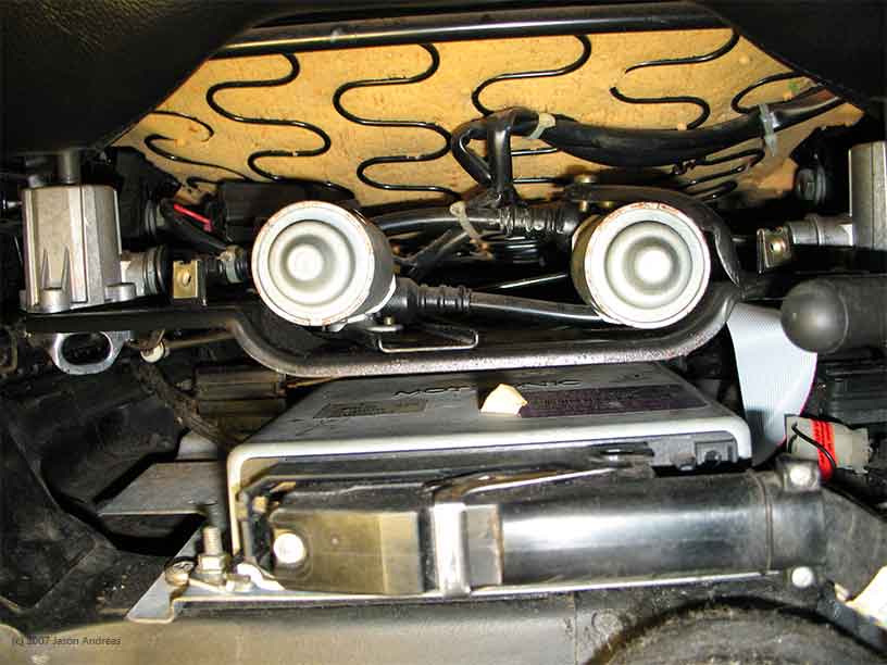
On vehicles with sport seats raise the driver's side electric height adjustment (front & back) to the maximum position. Manually pull the fore-and-aft adjustment lever and move the seat as far back as possible. With fully electric comfort seats raise the lumbar support height adjustment to the maximum position and use the electric fore-and-aft adjustment to move the seat as far back as possible. You want as much room underneath the front of the seat as you can get.
Step 2:
Disconnect the battery ground cable
Step 3:
Remove the two phillips-head screws attaching the black plastic cover for the emergency fore-and-aft adjustment to the seat frame.
This gives you a little more room and a better view of the rear fasteners.
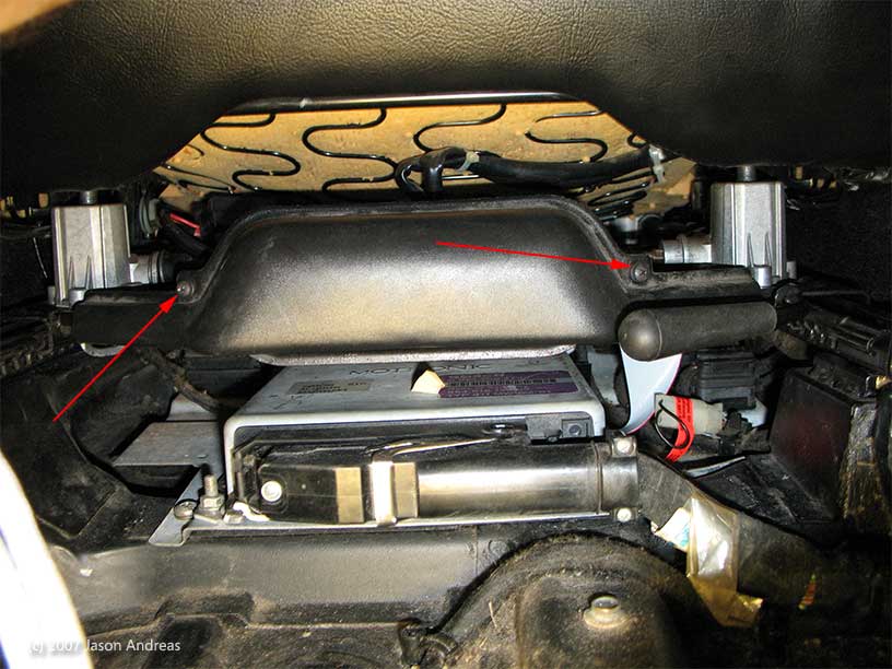
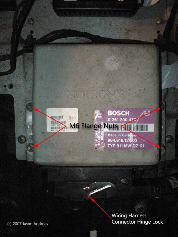
Step 4:
With a 10mm long socket remove the 4 M6 flange nuts fastening the ECU to the floorboard (a regular wrench will work but it takes forever.) Lift the ECU upward and off the mounting studs and then (with the wiring harness still connected) pull the unit out from under the seat. and THEN unlock the wiring harness connector lock and unhinge (like you're opening a door, rotate the ECU slightly) the ECU from the connector.
Step 5:
Put your anti static wrist strap on or at the very least discharge any static charge from your body before you take the ECU apart.
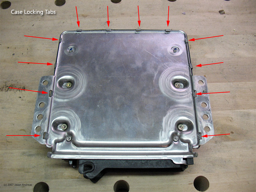
Step 6:
With needle nose pliers and a swiss-army knife or thin blade flat-head screwdriver bend the 12 ECU cover locking tabs 90� degrees (to vertical).
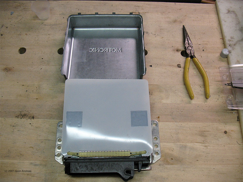
Step 7:
Remove the cover.
Step 8:
On the plastic 55-pin connector locate the two PCB locking tabs
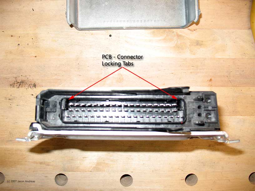
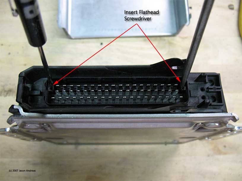
and insert two flat-head screwdrivers, pushing the locking tabs towards the pin contacts.
Step 9:
On the opposite side of the ECU locate the two yellow scaffolding supports.
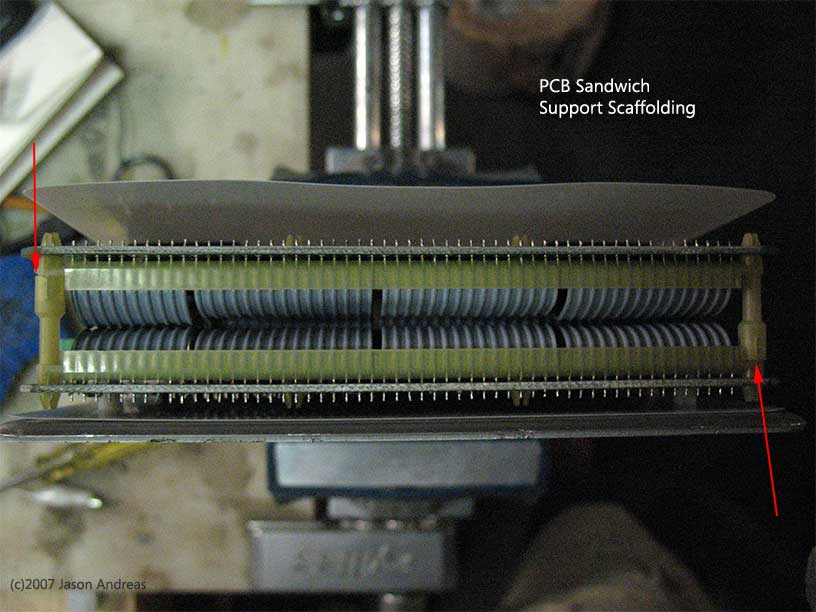
and separate them at the red arrows.

Step 10:
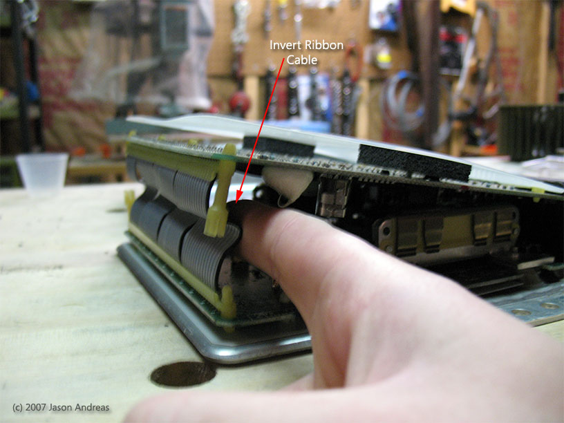
To separate the circuit boards there is a simple trick, notice how the ribbon cable is facing inwards towards all the components?
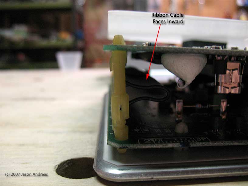
Take a finger or two and push against the ribbon cable, forcing it outward and inverted. The action of pushing from that angle and position will pull the upper PCB from the plastic connector and allow you to separate the two circuit boards. Otherwise you will spend 20 minutes fighting with boards trying to separate them. Be careful not to push against any of the PCB electrical components.
Step 11:
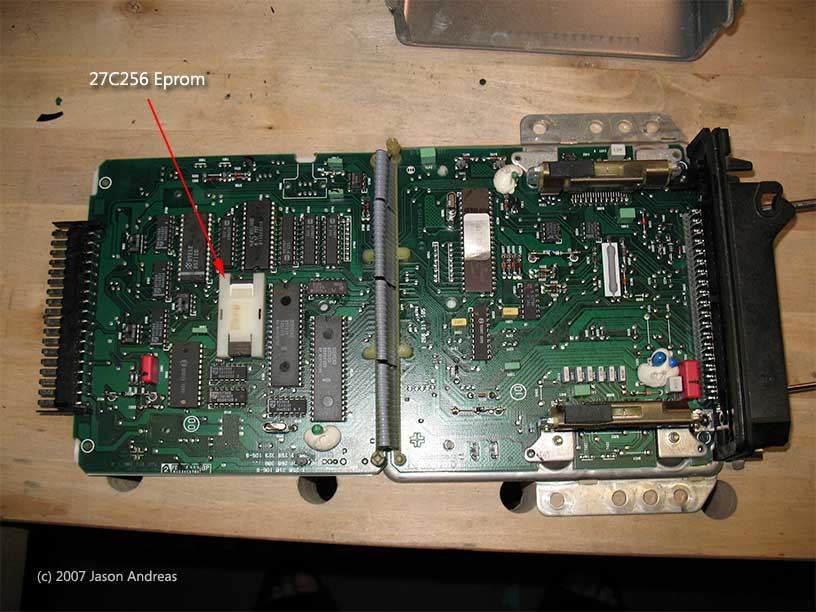
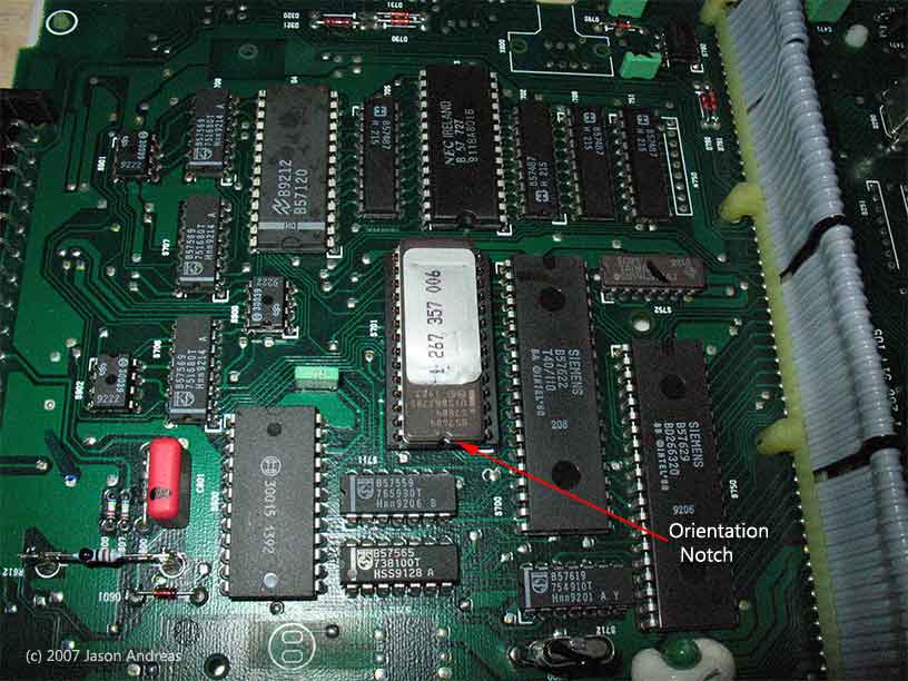
Locate the EPROM on the upper circuit board
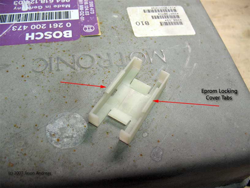
Step 11:
Remove the white plastic EPROM locking cover by slightly bending the two side tabs that lock the chip to the socket. If you just pull on the white cover without first doing this nothing will happen and you'll end up ripping socket from the circuit board.
Step 12:
Remove the EPROM and install the new one, making sure the orientation notch on the new chip points in the same direction.
and that's it...
Step 1:
On vehicles with sport seats raise the driver's side electric height adjustment (front & back) to the maximum position. Manually pull the fore-and-aft adjustment lever and move the seat as far back as possible. With fully electric comfort seats raise the lumbar support height adjustment to the maximum position and use the electric fore-and-aft adjustment to move the seat as far back as possible. You want as much room underneath the front of the seat as you can get.
Step 2:
Disconnect the battery ground cable
Step 3:
Remove the two phillips-head screws attaching the black plastic cover for the emergency fore-and-aft adjustment to the seat frame.
This gives you a little more room and a better view of the rear fasteners.
Step 4:
With a 10mm long socket remove the 4 M6 flange nuts fastening the ECU to the floorboard (a regular wrench will work but it takes forever.) Lift the ECU upward and off the mounting studs and then (with the wiring harness still connected) pull the unit out from under the seat. and THEN unlock the wiring harness connector lock and unhinge (like you're opening a door, rotate the ECU slightly) the ECU from the connector.
Step 5:
Put your anti static wrist strap on or at the very least discharge any static charge from your body before you take the ECU apart.
Step 6:
With needle nose pliers and a swiss-army knife or thin blade flat-head screwdriver bend the 12 ECU cover locking tabs 90� degrees (to vertical).
Step 7:
Remove the cover.
Step 8:
On the plastic 55-pin connector locate the two PCB locking tabs
and insert two flat-head screwdrivers, pushing the locking tabs towards the pin contacts.
Step 9:
On the opposite side of the ECU locate the two yellow scaffolding supports.
and separate them at the red arrows.
Step 10:
To separate the circuit boards there is a simple trick, notice how the ribbon cable is facing inwards towards all the components?
Take a finger or two and push against the ribbon cable, forcing it outward and inverted. The action of pushing from that angle and position will pull the upper PCB from the plastic connector and allow you to separate the two circuit boards. Otherwise you will spend 20 minutes fighting with boards trying to separate them. Be careful not to push against any of the PCB electrical components.
Step 11:
Locate the EPROM on the upper circuit board
Step 11:
Remove the white plastic EPROM locking cover by slightly bending the two side tabs that lock the chip to the socket. If you just pull on the white cover without first doing this nothing will happen and you'll end up ripping socket from the circuit board.
Step 12:
Remove the EPROM and install the new one, making sure the orientation notch on the new chip points in the same direction.
and that's it...
 06-23-2007, 08:26 AM
#2
Three Wheelin'

Join Date: Dec 2004
Location: Halifax, Nova Scotia , Canada
Posts: 1,779
Likes: 0
Received 0 Likes
on
0 Posts
Jason,
I have never found it necessary to take off the front seat motor cover .
I also dont bother with the battery disconnect !The DME plug does that for you !
I dont understand on step 6 the mention of 4 Torx screws .
The ribbon idea could be OK . I have always just rammed my fingures between top and bottom rear posts and given a tug to seperate the rear boards.
Could be worth mentioning that the front top pins release can be pretty tight on a DME that is a virgin !
I must have pulled a few hundred of these DMEs apart so I am probably taking a casual view to the whole process .
Very well done in making available some very good pictures.
Geoff
----------------------------------------------------------------
KS400200,the oldest 964 on Rennlist,unless you know differently !
06-23-2007, 02:39 PM
#3
Technical Guru
Rennlist Member
Rennlist Member
Thread Starter
Originally Posted by Red rooster
I have never found it necessary to take off the front seat motor cover .
Originally Posted by Red rooster
I also dont bother with the battery disconnect !The DME plug does that for you !
Originally Posted by Red rooster
I dont understand on step 6 the mention of 4 Torx screws .