
Design your own Dual Spring-Rate Coilovers
 04-02-2009, 04:12 PM
#16
Burning Brakes
I don�t think your Bilsteins would benefit much from this dual spring package, if you are already using 250# springs, then going to the combo 214# rate, the rates are so similar that I doubt you would be able to tell the difference.
As I mentioned in my original post, one of the major factors in having a comfortable street ride is being able to adjust your damping rates down to the softest settings. Perhaps you could give Bilstein USA a call and ask them to convert your Escort Cup struts to adjustables ala PSS9 or PSS10 style. There is NO technical reason why they would not be able to do it, however, I suspect that $$$ might be an issue here. Bilstein USA @ 1-858-386-5900. or http://www.bilstein.com/contact.php
Once you have adjustable struts, then you can come back and play with us�
one thing i will add is that in my opinion, bilsteins are soooo much more effective as dampers than konis. they also claim to have a self adjusting feature so that they change as the frequency changes although i honestly don't know how. all i know is that they seem to work much better than konis, effectively dampening slight wheel movement without as stiff of a ride as konis.
therefore, i think bilsteins would be able to handle the differences in spring rates and still ride better while maintaining proper dampening.
 04-02-2009, 04:34 PM
#17
Drifting
Join Date: Mar 2006
Location: midwest
Posts: 2,931
Likes: 0
Received 0 Likes
on
0 Posts
one thing i will add is that in my opinion, bilsteins are soooo much more effective as dampers than konis. they also claim to have a self adjusting feature so that they change as the frequency changes although i honestly don't know how. all i know is that they seem to work much better than konis, effectively dampening slight wheel movement without as stiff of a ride as konis.
therefore, i think bilsteins would be able to handle the differences in spring rates and still ride better while maintaining proper dampening.
therefore, i think bilsteins would be able to handle the differences in spring rates and still ride better while maintaining proper dampening.
Is your experience is based on used, perhaps worn out/high mileage koni units?
My experience is exactly the opposite:
With mo30 konis, 375# spring on a soft setting, 968 mo30 sway, very well mannered for street use. There is enough damping for almost all bumpy roads, and light enough damping to handle potholes. For most track use I run near full hard setting. This is the entire key to enjoying my car and keeping it street able enough my wife doesn't mind riding in it.
Have ridden in bilstein (escort) damped, 400#, and 450# cars. Talk about rough on the street ........ by far more abrupt than my konis with softer setting.
hence my confusion by such comments - please elaborate if you have more setup details or pertinent info to share
04-02-2009, 04:54 PM
#18
Burning Brakes
well, i'm talking about the cheapo konis vs. the cheapo bilsteins, circa $100 per shock. and i constantly blow out konis, both on the 951 and moreso on a vw A1 chassis. so much that i've given up on konis for the vw and i love the bilsteins. to me konis at full soft don't dampen enough. at full stiff they are also pretty useless so that i always end up using about half way in between and never really find the ideal setting. i will admit that it's nice to have the adjustability but i just wish there was more of it or maybe i need the double adjustable.
but the blowing out is just unforgivable. these shocks should last forever. that's why we buy them. and i know about the lifetime warranty but some have been OEM, some have been bought used, and some have been traded in countless times until i just got sick of it and went with bilsteins.
i admit a lot of my bias is based on the vw chassis which is notorious for no travel , around 2-3 inches once lowered. i was actually enjoying my 951 konis until i blew a rear one again. so now i'm trying to decide whether to switch to bilsteins or more konis.
04-02-2009, 05:11 PM
#19
Drifting
Join Date: Mar 2006
Location: midwest
Posts: 2,931
Likes: 0
Received 0 Likes
on
0 Posts
oh **** man - you are talking about junk compared to junk 
That explains alot. Thank you for clarification.
One other question - are you saying the chepie koni (bottm end) shock/struts are rebound adjustable?
That explains alot. Thank you for clarification.
One other question - are you saying the chepie koni (bottm end) shock/struts are rebound adjustable?
04-02-2009, 09:48 PM
#20
Burning Brakes
and yup, koni single adjustable adjust the rebound and not the compression.
04-03-2009, 02:55 AM
#21
Pro
Join Date: Dec 2008
Location: Seattle
Posts: 597
Likes: 0
Received 0 Likes
on
0 Posts
Trucho,would this also work with Motons or Leda's as I'm running 550# springs now and would love to lose the pogo effect on the street.There are 1826 expansion joints between me and the track,YES I have counted them.
04-04-2009, 09:08 AM
#22
Pro
Thread Starter
Join Date: Jun 2005
Location: Napa Valley, CA
Posts: 589
Likes: 0
Received 0 Likes
on
0 Posts
I am not familiar with Leda�s or Motons.
 In principle, yes it should work, however, as we all know, it always comes down to the details. Could you post of picture of your system? Perhaps someone who is familiar with their dimensions/specs. can chime in.
 Absent that, and going with just a wild *** guess, I would say that you have a shot at making it work if: #1) you have at least 2 inches of threads below you lower spring perch (assuming you are running an 8 inch 550# spring). If you are running a 10 inch spring now, that would make things so much easier. #2) whether you can find Tender springs and sliders for your struts. If not, well, there are always work arounds any temporary setbacks, but it just takes a little more effort. Are you running stockfish ride height or are you running a lowered slammed car?
04-04-2009, 09:14 AM
#23
Pro
Thread Starter
Join Date: Jun 2005
Location: Napa Valley, CA
Posts: 589
Likes: 0
Received 0 Likes
on
0 Posts
Ok, for the guys that have been asking, I’ve been working on Section III during every possible break and have it completed. I will be posting it in a few minutes. However, it’s turned out to be a very, very long post.
Warning, warning!!! it’s a whopper! So don’t expect to get through it all in one sitting…. I hope you enjoy reading it as much as I enjoyed writing it. However, my brain is now mush, so Sections IV, and V will have to wait until I get a little R & R.
Warning, warning!!! it’s a whopper! So don’t expect to get through it all in one sitting…. I hope you enjoy reading it as much as I enjoyed writing it. However, my brain is now mush, so Sections IV, and V will have to wait until I get a little R & R.
04-04-2009, 09:43 AM
#24
Pro
Thread Starter
Join Date: Jun 2005
Location: Napa Valley, CA
Posts: 589
Likes: 0
Received 0 Likes
on
0 Posts
How to Design your own Dual Spring-rate Coilover Suspension 4/4/2009
*** For this suspension set-up to work properly, it will require the use of struts with adjustable damping rates and adjustable spring perches.
I. Measurements, measurements, measurements!
Every car is set up differently. Since there are virtually endless number of combinations of camber plates, spring hats, strut brands, etc., before ordering any parts for your suspension mod, the first step is to take your own measurements and be exactly sure of what you are working with. The more you know about your car’s specific suspension set-up, the better your suspension mods will turn out. So what shall we measure first?
1. Ride height. Ride height is one of the most important suspension measurements to know. So let’s start by setting the car at your desired ride height. Measure from the ground to the fender lip (e.g., 25 �”). Also, since desired ride height has so much to do with personal preference, what looks good to us, make sure you are using your favorite wheel/tire combo.
2. Because this ride height measurement will change depending on the tire size being used, it is important to convert it to a “centerline measurement”. This will normalize the measurement so as to keep suspension calculations consistent. We need to convert this ride height measurement to a distance between the fender lip and the spindle (or hub cap) centerline (e.g., 13 �”). So on my car, a 25 �” ground to fender lip distance = 13 � “ spindle centerline to fender lip distance.
3. Bottoms up? No, no, too early for that, I mean, “bottoms-out.” This is what happens when the suspension compresses over a big bump and the tire hits the inner fender. So lets measure the distance between the hub cap centerline and the inner fender (e.g. 16“).
4. Droop – to hang low. How far can the suspension extend to deal with road irregularities such as potholes? Raise the car and let both front tires droop down as far as they will go. Measure the distance between the fender lip and the center cap centerline (e.g., 15 � “).
The above four measurements will form the basis for correctly designing your desired suspension set-up. Most all important suspension calculations will be derived from or will be linked to these four measurements.
For example, What is the maximum suspension travel in the bump direction (under compression)? Well, from the example measurements above: Maximum bump = 3 �” = 16” – 12 � “. Where 12 � “ is the radius of my front 225/45-17 street tire (a 25” diameter tire).
Next, let’s determine the available amount of suspension droop (rebound travel starting at normal ride height):
Droop = 1 � “ = 15 � “ – 13 �” The suspension can handle 1 � “ deep potholes with out the tire becoming airborne.
II. The Bump Stop is your friend. Really, he is! Making changes for the sake of safety.
The best time to find out what happens when our suspension bottoms out is now, while we are in measuring mode - not when we’re veering down the road at triple digit speeds (oops!....I meant to say double digit speed).
Of course this section is more important for lowered cars, but even non lowered car can benefit from having the bump stop work for you, not against you, or even worse NOT work at all. So in the section on lowering a car we will revisit our friend the bump stop in much greater detail.
In dealing with the bump stop provided with the Yellow Koni’s (free length of 2 1/8 “ ), it turns out that it is relatively easy to squish it the first � “. The second � “ of squish becomes exponentially harder to do. That is because one is trying to cram the entire bump stop into a space only 5/8 “ tall, by that time even this soft Pillsbury dough boy little guy will refuse to be pushed around anymore. This foamy material has been turned into pretty much a solid – it has reached it’s “block length.”
So what we want to know is, “where is the tire in relation to the inner fender when the suspension, i.e., top of the Koni strut is only 5/8 “ from hitting the upper spring hat?” That is to say, is our friend the bump stop going to help us from not smashing our tires into the inner fender when the suspension bottoms out? Or is he being useless and sort of out of the way? Or is he too much in the way? We need to know for sure that he exactly where he’s supposed to be.
So then, one of our main suspension goals will be to have our suspension “adjusted” so that when there is only a 5/8 “ space between the top of the Koni and the upper spring hat, that the tire can still spin freely and is not rubbing on the inner fender. We want to be able to safely utilize all potentially available suspension travel.
1. Make a 5/8 “ thick circular spacer (I didn’t want to use the word “annulus” because it might make some of you laugh, and not that that’s a bad thing, but I don’t want you to spill your beer). So let’t think of this spacer of having more of a dougnut shape, anyway, � “ plywood is a good easy candidate material, because as we all know, � “ plywood is not � “ after all (it’s more like 23/32 “ , close enough). The outer diameter should be small enough to fit inside the upper spring hat (maybe 2 �” ?). The inner diameter 7/8” so that it may slide on the Koni strut shaft.
2. Remove the front wheel, disconnect the sway bar, remove the strut, remove the spring and the bump stop. Now reinstall the strut without the spring (only install the upper spring hat and your high tech 5/8 “ wooden spacer you just made.) Now using a hydraulic jack along with blocks of wood to protect the aluminum control arm from damage, raise the control arm until the Koni strut and wooden spacer bottoms out on the upper spring hat.
3. Measure the inner fender to hub cap centerline distance. Is it less than 12 � “? Remember, 12 � “ is where a 25” tire would hit the inner fender (also remember to jot down the corresponding fender lip to hub cap centerline measurement – it will come in handy later on for quick suspension checks).
If the distance is less than 12 �”, then we have a problem with the type of camber plate/upper spring hat installation. Make the necessary changes to these components until the measurement is close to but not less than 12 � “ (or whatever the radius of your preferred wheel/tire combo). For your own safety, please do not continue any further with suspension mods, until this issue has been resolved.
Is the measurement a lot bigger than 12 � “? That means that we are not going to be able to tap into all the potentially available suspension travel. Again this issue needs to be resolved, pronto!
Suspension choices might include: the type of camber plates being used (e.g., raised, semi-raised, or flat), top mounted or bottom mounted. As a last resort for obtaining additional suspension travel, the Koni insert can be lowered � “ into the strut housing… more on this later.
4. Ok, now that we’ve got that major safety issue taken care of and we are feeling safe and secure… It’s time to move on. Next, remove the strut again. This time reinstall it without the spring – but this time use the regular 2 1/8 “ Koni bump stop and your upper spring hat.
5. Using the hydraulic jack and the wood block to protect the lower control arm, raise the suspension, but this time go only up your desired ride height (e.g. 13 � “ fender lip to hub cap centerline).
****
6. Now measure the distance between the top of the Koni strut and the bottom of the bump stop (e.g. 1 7/8 “ ). Guard this measurement with your life, congratulations my friend, you now have in your possession the key to the universe!!! Really, I mean that. Not to mention, now you can begin plugging information in to the Excel spreadsheet that I will attempt to attach below…
7. If you were one of the ones that made “adjustments” to you upper suspension mounting point as discussed in #3 above, then you will need to re-measure the amount of droop. So let the suspension hang to its lowest point, and record the distance between the fender lip and the hub cap centerline. Also this is a good time to measure the distance between the top of the Koni and the bottom of the bump stop: this distance is the TOTAL available strut stroke – no matter what the manufacturer’s advertised stroke was, this is what is available on your car.
Dynamics, Statics…the study of forces.
Basic Physical Concepts, Dynamics:
First I would like to place into context how the assumptions put into place here have come about. After reading a number of books (e.g., Porsche High-Performance Driving Handbook by Vic Elford; Going Faster by The Skip Barber Racing School, also attending their Car Control Clinic, and other Driving Classes, and attending numerous NASA HPDE events over the past four years ; practically memorizing Speed Secrets: Professional Race Driving Techniques by Ross Bentley; and last but most importantly reading and re-reading: How to Make Your Car Handle by Fred Puhn – an old little book, but jammed packed with timeless pearls of wisdom), I felt that I was starting to get a decent handle on chassis dynamics and the physics at work as we are out playing at our favorite race track.
So I’ve tried to distill and simplify some of that information into its most basic physical concepts. So no, we are not going to be calculating instantaneous centers, roll centers, and/or roll moments, well…, at least not for now, but perhaps in a later section dealing with lowering a car to obtain better cornering potential.
I know the experts in the crowd will probably gag and spill beer our of their noses as they read the following oversimplified almost cartoonish model of chassis dynamics, but it’s not the first time I’ve made people laugh, so here is the simplified version:
What happens as we approach a corner and we know we are going too fast to make it around the bend while still managing to keep all four tires on the paved portion of the track?
Brakes, brakes, brakes! Not only does this slow us down to an appropriate speed, most importantly it loads the front wheels for better grip. That’s great, we now have more grip at the front, but where did that extra weight come from? Yes, it was shifted from the rear of the vehicle. Now as we begin to corner, a similar phenomena occurs, weight is shifted from the side of the vehicle facing the “inside side of the curve” to the outside side. (Something to do with centripetal/centrifugal force… you say tomato, I say tomatoe).
So in final form, at corner entry, the outside front wheel takes the brunt of all this weight that has shifted around. But where did most of this weight come from, of course, all together now…. It came from the inside rear corner.
If we take this cornering scenario to its EXTREME, then one can reasonably assume that it might be possible to shift ALL of the inside rear corner weight to the outside front corner plus a little from the inside front. The vehicle is now traveling towards the apex while riding on three wheels.
Yes, I think it’s worth repeating, at full “1.5 g” cornering, the car is basically traveling around on three wheels. The “right triangle” formed between those three wheels is your “traction platform”. Yeah, I know, 1.5 g cornerning, well I can dream can't I? Ok, you win, it's more like 1.0 g cornering. Anyway, the point is, the car is cornerning at its maximum ability.
This is a right triangle formed between the front outside wheel and the “hypotenuse”, i.e., the front inside to rear outside wheels, this is all we have working for us. The wheels on the hypotenuse, however, serve mainly as a hinge about which the chassis rolls, but it is the outside front wheel that is doing the majority of the cornering work.
**** So if we proceed with this assumption, i.e., that the front outside corner suspension is supporting approximately twice the load it had before we began our cornering attempt, then we can begin to figure out how stiff that spring needs to be.
But wait… I can hear someone in the audience asking, “what happens to the weight distribution as one leaves the corner entry phase and heads towards the apex, and beyond?” Well, I’m glad someone asked that, because a very interesting shift occurs as we transition off the brakes and begin rolling on the throttle. Of course at first it’s mainly “maintenance throttle” applied to merely to maintain a little load on the rear outside corner - just enough to keep the car from fish tailing. However, as we deliberately begin to apply more and more throttle to power through the turn and accelerate towards trackout, we also find that we need to simultaneously begin unwinding the amount of steering lock. Ah, there is the clue, so as we apply more throttle, the car is not only undergoing lateral acceleration, it’s now starting to accelerate more linearly. That must mean that the load to the rear springs is more dependent on the amount of torque produced by the engine, than the actual cornering forces…..very interesting.
**** Some internet discussion forums I’ve visited seem to advocate a minimum of 250 #/in wheel rate for cars that hover around the 300 RWHP range. What a coincidence, that’s approximately what I have now with my 28 mm torsion bars.
Of course this is over simplified, and if you find that you spend a lot of time at race tracks with long sweepers where the car dwells at mid-corner a lot more, or your are just plain and simply one heck of a driver and are going flat WOT by mid-corner, then the importance of stiffer rear springs, is well, more important.
But let’s return back to the front of the vehicle where most of the suspension action is taking place.
STATICS.
Understanding what forces are acting on the suspension components when the vehicle is at rest.
Without further adieu let’s begin our “force balance” analysis, we shall focus on the forces acting on the spring, the steering knuckle, and the lower control arm.
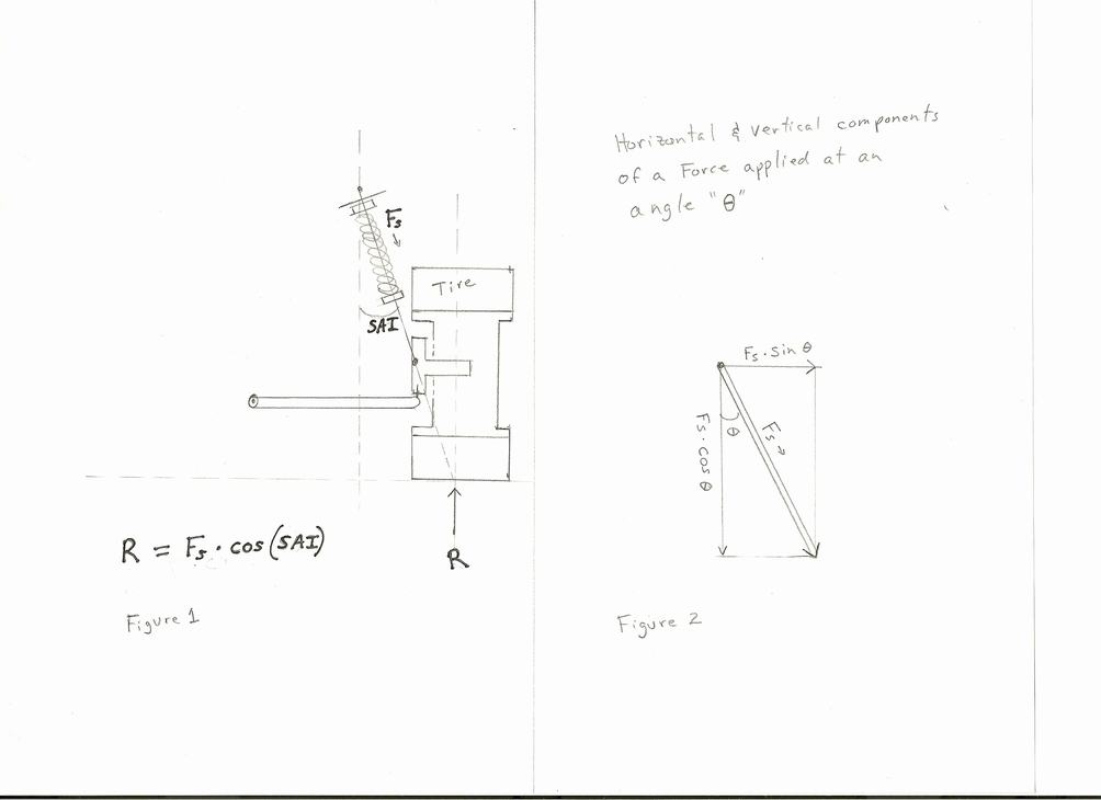
By studying the figures depicted above, we can surmise the following conditions:
1) With the vehicle at rest and the suspension parts not moving, we can conclude that all forces exerted on the system are in balance, i.e. their total sum = ZERO.
2) The corner weight of a well balanced vehicle exerts a load = � total vehicle weight acting through the chassis, down through the spring, into the steering knuckle, from there through the bearings onto the wheel/tire combo, and finally, on to the ground.
3) The ground responds with a resistant force acting back against the tire, this reaction force prevents the tire from sinking into the ground surface. We have labeled this reaction force as “R”,
4) The load exerted by the chassis onto the strut is resisted by the compressed spring. We have labeled the force from the spring: “Fs”,
5) The spring on our McPherson strut suspension is not installed vertically, it is installed at an angle. This angle is called the “steering axis inclination” angle (a.k.a., SAI ).
6) Because the spring is installed at an angle it exerts a force comprised of a vertical and a horizontal component onto the steering knuckle. The vertical vector of this force we have labeled: “Fsd” to signify the downward component of this spring force,
7) From trigonometry we know that Fsd = Fs*Cos (SAI)
Using the knowledge we gained from condition #1 stated above, we can then conclude that Fsd = R; obtained by rearranging the equation to Fsd – R = 0 (in other words, the sum of the vertical forces is equal to ZERO).
We also know that a 1986 951 is lighter than the later 951’s, the typically reported wet weight on Rennlist varies somewhat but hovers around 2900 lbs. (or we can pay to get our own vehicle weighted).
This yields a corner weight of: 725 lbs = 2900 / 4
725 lbs is the reaction force "R" the ground surface exerts back onto the vehicle so that it will not sink into the ground.
By including the information from conditions #7, we can now determine that
725 lbs = Fs * Cos (SAI)
We know from the Porsche manuals that for a 1986 951 the SAI = 15 degrees, and SAI = 25 degrees for the 1987 and later cars with longer control arms.
Therefore for a 1986 car, 725 lbs = Fs * Cos 15 deg.
Solving this equation yields Fs = 750 lbs = 725 / 0.9659
**** This means that with the vehicle at rest, the spring is experiencing a compressive force equal to 750 lbs.
From our “Dynamics” section above, we can estimate that the spring is being compressed by double that force when the vehicle is cornering at its maximum, i.e., the spring would be compressed by a force equal to 1500 lbs.
Let the Design Process Begin… Release the hounds I say!!!
Now we can answer the $64,000 question: What is the minimum spring stiffness that I need for my “RACE Car?”
Retrieve the “key to the universe.” The information we obtained with our measurements above in Section II, The bump stop is your friend, Step #6.
We know that the available free strut travel in my car is equal to 1 7/8 inches.
So the answer to this questions is:
400 lb/in = 750 lbs /1.875 inches, ahhh, Gottcha!, we did not use 1500 lbs, because as you will recall, at normal ride height the spring has already been compressed to resist the first 750 lbs of corner weight. The available travel only needs to resist the additional 750 lbs of force due to the weight transfer coming from the rear inside corner.
So now we know that for a single spring system, a 400 # spring will suffice. This is only a rough estimate, however, because a car does not drive by itself. There is usually at least one person in it - and at least � to � tank of gas. So if we redo this calculation by adding in a 200 # driver plus 100 # of fuel, our revised corner weight becomes 800 # = 3200 / 4. Our new spring calculation yields a necessary minimum spring stiffness of 442 #/in = (800/0.9659) / 1.875
But if we do not want to run a 442# spring because we also drive a lot on the street, and street comfort is also important to us, then we have a dilemma. Do we spring the car softer for street comfort which in turn will cause us to have less than ideal free travel at the track, or do we just bite the bullet and spring stiffer for the track and accept whatever the street ride quality turns out to be?.
What if we want both, great street comfort AND race track cornering potential?
Cue in the Dual Spring Coilover package…. Yes, you can have your cake and eat it too.
As was explained in the original post, a comfortable street ride is dependent on having both the ability to set the dampers to soft settings, and also having a soft initial spring rate so as to be able to absorb bumps on the road where the resultant spring deflections do not generate sufficient force to jar the vehicle chassis. Hence obtaining that, “Hey…, did we just go over the rail road tracks?” feeling; as opposed to that, “Ok, hold on to your nuts!!!, cause we’re going over those railroad tracks!”
But before we begin playing around with dual spring systems, let’s take a moment to understand the following three major topics
- Initial Combination Rate
- Crossover Height
- Total Block Length
To shed some light on to how the initial rate works its magic, lets imagine we have stacked two identical springs on top of each other and placed them on the ground, and we have placed a steel plate to separate the two springs from each other. To simplify the math, let’s assume each spring has a stiffness rate constant k = 550 lbs/in.
As we apply a weight, of say 750 lbs, on this dual spring system, the compressive force will cause the top spring to compress according to its spring constant. The spring will stop compressing when it’s reaction force is equal to the load being applied to it. So this spring will compress until it has reached a total deflection of 1.36 inches ( 1.36” = 750 / 550). At this point the spring exerts a force of 750 lbs onto the steel plate as it support the 750 lbs of load we placed on it.
Next, lets take a look at the bottom spring. All it knows is that it is being squeezed between a steel plate on one side and the ground surface on the other side. Since we know that the top spring generates a reaction force of 750 lbs against the steel plate, then we know that the bottom spring will compress until it also generates a reactive force equal to 750 lbs needed to resist the force exerted by the steel plate. The bottom spring will also compress until it reaches a total deflection of 1.36 inches ( 1.36” = 750 / 550 ).
Therefore, the total movement of our dual stacked spring system is equal to 2.72 inches = 1.36 + 1.36 The resulting combination spring rate is equal to Kcombo = F/X.
Kcombo = 276 #/in = 750 / 2.72
So there we have it. Two 550# stiff springs stacked in series behave as would a softer single 276 # spring.
The general formula for computing the combination rate, Cf, for two springs of dissimilar rates stacked in series is:
1/Cf = 1/C1 + 1/C2
I changed to using the letter “C” instead of “k” because the formula looks better to me.
The second important concept is called the “crossover height.” Essentially all this is is how much movement can both springs contribute until one of them bottoms out. Because after that point, any additional compression will occur as a single rate system. Therefore COH is the amount of suspension travel in “combo” mode.
To be able to calculate crossover height, one needs to know the block length of the first spring to bottom out. Block length is defined as the height of the spring when it has been compressed to coil bind, and essentially now acts as a solid block.
Starting from vehicle ride height, the formula to calculate the crossover height is:
COH = Available Tender Travel * (1 + Ct / Cm)
Ct = tender stiffness
Cm = main stiffness
To me, knowing the COH is important because if gives me an indication of how “sloppy” the suspension will be. A small COH will result in very little combo travel, hence, the system will be tight and exhibit very little chassis roll, however, at the expense of less comfort. Conversely, a system with a large COH will exhibit more chassis roll, but will be more comfortable. What is the correct COH? Ultimately it will come down to personal preference and the available of bump travel.
Final topic of discussion: Total Block Length
Last but not least, for the sake of safety (yes, safety again!), it is necessary to have the suspension bottom out on our friend the bump stop before the system compresses down to Total Block Length. The reason, hopefully quite obvious by now, it’s better to bottom out on to a soft pillow than to bottom out on to a solid block of metal. All your suspension parts will thank you for that.
So as a final check, check that the distance from lower spring perch to top of Koni + 5/8 “ is greater than the sum of both spring block lengths plus the thickness of your spring divider.
V. Springs, Springs, springs… Spring is nature's way of saying, "Let's party!"”
Robin Williams
We need spring specs, but where to obtain this valuable info? Below are some suggested sources:
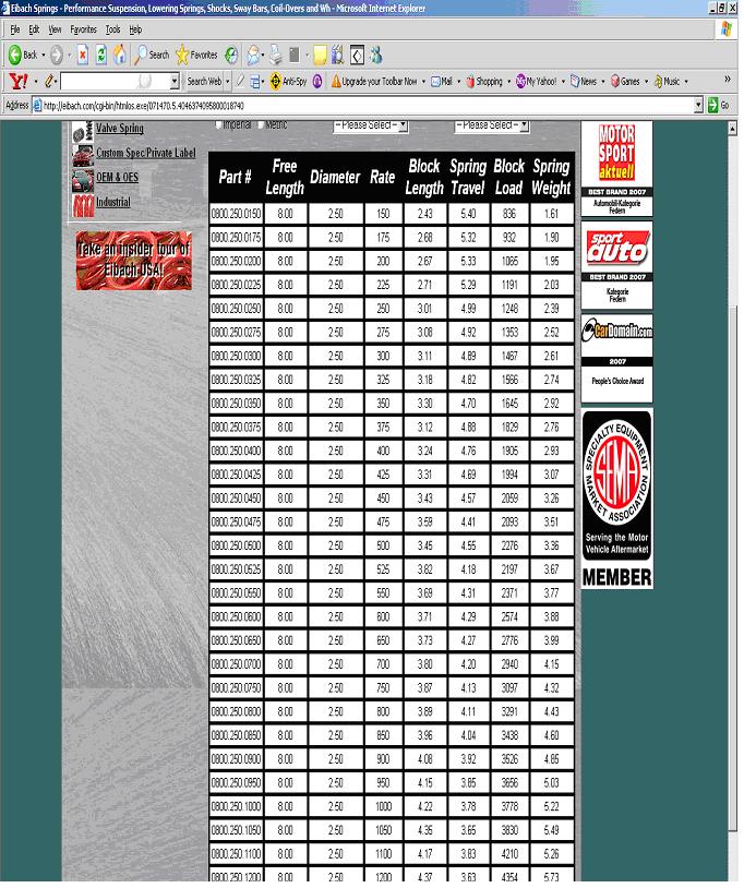
Eibach.com
ERS Eibach Racing Spring page
Listed 8 inch spring information includes: Part number, Free Length, Rate, Block Length, Spring Travel, Block Load.
Hypercoil 2.5 inch ID spring catalog:
http://www.hypercoils.com/PDF/page_12.pdf
Hypercoil Block length formula: BL = (#coils – 0.25)*(wire diameter)
e.g. BL = (14 – 0.25)* 0.5” = 6.875 “
So let number crunching begin!
Since I can’t seem to find a way to post the spreadsheet, if anyone is interested in a copy, pm me your email address and I send it to you.
Snap shot of handy spreadsheet…
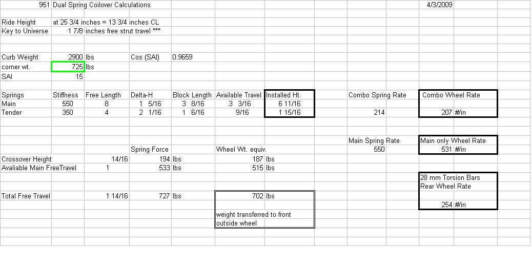
We are now ready to go out and play, however, it might be a good idea to check the spring installed heights to verify that reality agrees with your estimates. One easy way of doing this is to install a spare wheel with no tire on it. This allows plenty of access space to the springs. I use a few stacked 2 x 4 ‘s and maybe a few helper wooden shims to lower the wheel onto and help set the car back to ride height. Feel free to play around with either curb weight and/or the SAI angle in order to "calibrate" your spreadsheet spring installed height estimates.
In fact, it may be a good idea to use your "old" springs in order to calibrate the spreadsheet before proceding and pushing the "buy now" button and ordering your new dual spring setup.
Now, it’s time to go and enjoy our new suspension, happy pothole hunting!

*** For this suspension set-up to work properly, it will require the use of struts with adjustable damping rates and adjustable spring perches.
I. Measurements, measurements, measurements!
Every car is set up differently. Since there are virtually endless number of combinations of camber plates, spring hats, strut brands, etc., before ordering any parts for your suspension mod, the first step is to take your own measurements and be exactly sure of what you are working with. The more you know about your car’s specific suspension set-up, the better your suspension mods will turn out. So what shall we measure first?
1. Ride height. Ride height is one of the most important suspension measurements to know. So let’s start by setting the car at your desired ride height. Measure from the ground to the fender lip (e.g., 25 �”). Also, since desired ride height has so much to do with personal preference, what looks good to us, make sure you are using your favorite wheel/tire combo.
2. Because this ride height measurement will change depending on the tire size being used, it is important to convert it to a “centerline measurement”. This will normalize the measurement so as to keep suspension calculations consistent. We need to convert this ride height measurement to a distance between the fender lip and the spindle (or hub cap) centerline (e.g., 13 �”). So on my car, a 25 �” ground to fender lip distance = 13 � “ spindle centerline to fender lip distance.
3. Bottoms up? No, no, too early for that, I mean, “bottoms-out.” This is what happens when the suspension compresses over a big bump and the tire hits the inner fender. So lets measure the distance between the hub cap centerline and the inner fender (e.g. 16“).
4. Droop – to hang low. How far can the suspension extend to deal with road irregularities such as potholes? Raise the car and let both front tires droop down as far as they will go. Measure the distance between the fender lip and the center cap centerline (e.g., 15 � “).
The above four measurements will form the basis for correctly designing your desired suspension set-up. Most all important suspension calculations will be derived from or will be linked to these four measurements.
For example, What is the maximum suspension travel in the bump direction (under compression)? Well, from the example measurements above: Maximum bump = 3 �” = 16” – 12 � “. Where 12 � “ is the radius of my front 225/45-17 street tire (a 25” diameter tire).
Next, let’s determine the available amount of suspension droop (rebound travel starting at normal ride height):
Droop = 1 � “ = 15 � “ – 13 �” The suspension can handle 1 � “ deep potholes with out the tire becoming airborne.
II. The Bump Stop is your friend. Really, he is! Making changes for the sake of safety.
The best time to find out what happens when our suspension bottoms out is now, while we are in measuring mode - not when we’re veering down the road at triple digit speeds (oops!....I meant to say double digit speed).
Of course this section is more important for lowered cars, but even non lowered car can benefit from having the bump stop work for you, not against you, or even worse NOT work at all. So in the section on lowering a car we will revisit our friend the bump stop in much greater detail.
In dealing with the bump stop provided with the Yellow Koni’s (free length of 2 1/8 “ ), it turns out that it is relatively easy to squish it the first � “. The second � “ of squish becomes exponentially harder to do. That is because one is trying to cram the entire bump stop into a space only 5/8 “ tall, by that time even this soft Pillsbury dough boy little guy will refuse to be pushed around anymore. This foamy material has been turned into pretty much a solid – it has reached it’s “block length.”
So what we want to know is, “where is the tire in relation to the inner fender when the suspension, i.e., top of the Koni strut is only 5/8 “ from hitting the upper spring hat?” That is to say, is our friend the bump stop going to help us from not smashing our tires into the inner fender when the suspension bottoms out? Or is he being useless and sort of out of the way? Or is he too much in the way? We need to know for sure that he exactly where he’s supposed to be.
So then, one of our main suspension goals will be to have our suspension “adjusted” so that when there is only a 5/8 “ space between the top of the Koni and the upper spring hat, that the tire can still spin freely and is not rubbing on the inner fender. We want to be able to safely utilize all potentially available suspension travel.
1. Make a 5/8 “ thick circular spacer (I didn’t want to use the word “annulus” because it might make some of you laugh, and not that that’s a bad thing, but I don’t want you to spill your beer). So let’t think of this spacer of having more of a dougnut shape, anyway, � “ plywood is a good easy candidate material, because as we all know, � “ plywood is not � “ after all (it’s more like 23/32 “ , close enough). The outer diameter should be small enough to fit inside the upper spring hat (maybe 2 �” ?). The inner diameter 7/8” so that it may slide on the Koni strut shaft.
2. Remove the front wheel, disconnect the sway bar, remove the strut, remove the spring and the bump stop. Now reinstall the strut without the spring (only install the upper spring hat and your high tech 5/8 “ wooden spacer you just made.) Now using a hydraulic jack along with blocks of wood to protect the aluminum control arm from damage, raise the control arm until the Koni strut and wooden spacer bottoms out on the upper spring hat.
3. Measure the inner fender to hub cap centerline distance. Is it less than 12 � “? Remember, 12 � “ is where a 25” tire would hit the inner fender (also remember to jot down the corresponding fender lip to hub cap centerline measurement – it will come in handy later on for quick suspension checks).
If the distance is less than 12 �”, then we have a problem with the type of camber plate/upper spring hat installation. Make the necessary changes to these components until the measurement is close to but not less than 12 � “ (or whatever the radius of your preferred wheel/tire combo). For your own safety, please do not continue any further with suspension mods, until this issue has been resolved.
Is the measurement a lot bigger than 12 � “? That means that we are not going to be able to tap into all the potentially available suspension travel. Again this issue needs to be resolved, pronto!
Suspension choices might include: the type of camber plates being used (e.g., raised, semi-raised, or flat), top mounted or bottom mounted. As a last resort for obtaining additional suspension travel, the Koni insert can be lowered � “ into the strut housing… more on this later.
4. Ok, now that we’ve got that major safety issue taken care of and we are feeling safe and secure… It’s time to move on. Next, remove the strut again. This time reinstall it without the spring – but this time use the regular 2 1/8 “ Koni bump stop and your upper spring hat.
5. Using the hydraulic jack and the wood block to protect the lower control arm, raise the suspension, but this time go only up your desired ride height (e.g. 13 � “ fender lip to hub cap centerline).
****
6. Now measure the distance between the top of the Koni strut and the bottom of the bump stop (e.g. 1 7/8 “ ). Guard this measurement with your life, congratulations my friend, you now have in your possession the key to the universe!!! Really, I mean that. Not to mention, now you can begin plugging information in to the Excel spreadsheet that I will attempt to attach below…
7. If you were one of the ones that made “adjustments” to you upper suspension mounting point as discussed in #3 above, then you will need to re-measure the amount of droop. So let the suspension hang to its lowest point, and record the distance between the fender lip and the hub cap centerline. Also this is a good time to measure the distance between the top of the Koni and the bottom of the bump stop: this distance is the TOTAL available strut stroke – no matter what the manufacturer’s advertised stroke was, this is what is available on your car.
Dynamics, Statics…the study of forces.
Basic Physical Concepts, Dynamics:
First I would like to place into context how the assumptions put into place here have come about. After reading a number of books (e.g., Porsche High-Performance Driving Handbook by Vic Elford; Going Faster by The Skip Barber Racing School, also attending their Car Control Clinic, and other Driving Classes, and attending numerous NASA HPDE events over the past four years ; practically memorizing Speed Secrets: Professional Race Driving Techniques by Ross Bentley; and last but most importantly reading and re-reading: How to Make Your Car Handle by Fred Puhn – an old little book, but jammed packed with timeless pearls of wisdom), I felt that I was starting to get a decent handle on chassis dynamics and the physics at work as we are out playing at our favorite race track.
So I’ve tried to distill and simplify some of that information into its most basic physical concepts. So no, we are not going to be calculating instantaneous centers, roll centers, and/or roll moments, well…, at least not for now, but perhaps in a later section dealing with lowering a car to obtain better cornering potential.
I know the experts in the crowd will probably gag and spill beer our of their noses as they read the following oversimplified almost cartoonish model of chassis dynamics, but it’s not the first time I’ve made people laugh, so here is the simplified version:
What happens as we approach a corner and we know we are going too fast to make it around the bend while still managing to keep all four tires on the paved portion of the track?
Brakes, brakes, brakes! Not only does this slow us down to an appropriate speed, most importantly it loads the front wheels for better grip. That’s great, we now have more grip at the front, but where did that extra weight come from? Yes, it was shifted from the rear of the vehicle. Now as we begin to corner, a similar phenomena occurs, weight is shifted from the side of the vehicle facing the “inside side of the curve” to the outside side. (Something to do with centripetal/centrifugal force… you say tomato, I say tomatoe).
So in final form, at corner entry, the outside front wheel takes the brunt of all this weight that has shifted around. But where did most of this weight come from, of course, all together now…. It came from the inside rear corner.
If we take this cornering scenario to its EXTREME, then one can reasonably assume that it might be possible to shift ALL of the inside rear corner weight to the outside front corner plus a little from the inside front. The vehicle is now traveling towards the apex while riding on three wheels.
Yes, I think it’s worth repeating, at full “1.5 g” cornering, the car is basically traveling around on three wheels. The “right triangle” formed between those three wheels is your “traction platform”. Yeah, I know, 1.5 g cornerning, well I can dream can't I? Ok, you win, it's more like 1.0 g cornering. Anyway, the point is, the car is cornerning at its maximum ability.
This is a right triangle formed between the front outside wheel and the “hypotenuse”, i.e., the front inside to rear outside wheels, this is all we have working for us. The wheels on the hypotenuse, however, serve mainly as a hinge about which the chassis rolls, but it is the outside front wheel that is doing the majority of the cornering work.
**** So if we proceed with this assumption, i.e., that the front outside corner suspension is supporting approximately twice the load it had before we began our cornering attempt, then we can begin to figure out how stiff that spring needs to be.
But wait… I can hear someone in the audience asking, “what happens to the weight distribution as one leaves the corner entry phase and heads towards the apex, and beyond?” Well, I’m glad someone asked that, because a very interesting shift occurs as we transition off the brakes and begin rolling on the throttle. Of course at first it’s mainly “maintenance throttle” applied to merely to maintain a little load on the rear outside corner - just enough to keep the car from fish tailing. However, as we deliberately begin to apply more and more throttle to power through the turn and accelerate towards trackout, we also find that we need to simultaneously begin unwinding the amount of steering lock. Ah, there is the clue, so as we apply more throttle, the car is not only undergoing lateral acceleration, it’s now starting to accelerate more linearly. That must mean that the load to the rear springs is more dependent on the amount of torque produced by the engine, than the actual cornering forces…..very interesting.
**** Some internet discussion forums I’ve visited seem to advocate a minimum of 250 #/in wheel rate for cars that hover around the 300 RWHP range. What a coincidence, that’s approximately what I have now with my 28 mm torsion bars.
Of course this is over simplified, and if you find that you spend a lot of time at race tracks with long sweepers where the car dwells at mid-corner a lot more, or your are just plain and simply one heck of a driver and are going flat WOT by mid-corner, then the importance of stiffer rear springs, is well, more important.
But let’s return back to the front of the vehicle where most of the suspension action is taking place.
STATICS.
Understanding what forces are acting on the suspension components when the vehicle is at rest.
Without further adieu let’s begin our “force balance” analysis, we shall focus on the forces acting on the spring, the steering knuckle, and the lower control arm.
By studying the figures depicted above, we can surmise the following conditions:
1) With the vehicle at rest and the suspension parts not moving, we can conclude that all forces exerted on the system are in balance, i.e. their total sum = ZERO.
2) The corner weight of a well balanced vehicle exerts a load = � total vehicle weight acting through the chassis, down through the spring, into the steering knuckle, from there through the bearings onto the wheel/tire combo, and finally, on to the ground.
3) The ground responds with a resistant force acting back against the tire, this reaction force prevents the tire from sinking into the ground surface. We have labeled this reaction force as “R”,
4) The load exerted by the chassis onto the strut is resisted by the compressed spring. We have labeled the force from the spring: “Fs”,
5) The spring on our McPherson strut suspension is not installed vertically, it is installed at an angle. This angle is called the “steering axis inclination” angle (a.k.a., SAI ).
6) Because the spring is installed at an angle it exerts a force comprised of a vertical and a horizontal component onto the steering knuckle. The vertical vector of this force we have labeled: “Fsd” to signify the downward component of this spring force,
7) From trigonometry we know that Fsd = Fs*Cos (SAI)
Using the knowledge we gained from condition #1 stated above, we can then conclude that Fsd = R; obtained by rearranging the equation to Fsd – R = 0 (in other words, the sum of the vertical forces is equal to ZERO).
We also know that a 1986 951 is lighter than the later 951’s, the typically reported wet weight on Rennlist varies somewhat but hovers around 2900 lbs. (or we can pay to get our own vehicle weighted).
This yields a corner weight of: 725 lbs = 2900 / 4
725 lbs is the reaction force "R" the ground surface exerts back onto the vehicle so that it will not sink into the ground.
By including the information from conditions #7, we can now determine that
725 lbs = Fs * Cos (SAI)
We know from the Porsche manuals that for a 1986 951 the SAI = 15 degrees, and SAI = 25 degrees for the 1987 and later cars with longer control arms.
Therefore for a 1986 car, 725 lbs = Fs * Cos 15 deg.
Solving this equation yields Fs = 750 lbs = 725 / 0.9659
**** This means that with the vehicle at rest, the spring is experiencing a compressive force equal to 750 lbs.
From our “Dynamics” section above, we can estimate that the spring is being compressed by double that force when the vehicle is cornering at its maximum, i.e., the spring would be compressed by a force equal to 1500 lbs.
Let the Design Process Begin… Release the hounds I say!!!
Now we can answer the $64,000 question: What is the minimum spring stiffness that I need for my “RACE Car?”
Retrieve the “key to the universe.” The information we obtained with our measurements above in Section II, The bump stop is your friend, Step #6.
We know that the available free strut travel in my car is equal to 1 7/8 inches.
So the answer to this questions is:
400 lb/in = 750 lbs /1.875 inches, ahhh, Gottcha!, we did not use 1500 lbs, because as you will recall, at normal ride height the spring has already been compressed to resist the first 750 lbs of corner weight. The available travel only needs to resist the additional 750 lbs of force due to the weight transfer coming from the rear inside corner.
So now we know that for a single spring system, a 400 # spring will suffice. This is only a rough estimate, however, because a car does not drive by itself. There is usually at least one person in it - and at least � to � tank of gas. So if we redo this calculation by adding in a 200 # driver plus 100 # of fuel, our revised corner weight becomes 800 # = 3200 / 4. Our new spring calculation yields a necessary minimum spring stiffness of 442 #/in = (800/0.9659) / 1.875
But if we do not want to run a 442# spring because we also drive a lot on the street, and street comfort is also important to us, then we have a dilemma. Do we spring the car softer for street comfort which in turn will cause us to have less than ideal free travel at the track, or do we just bite the bullet and spring stiffer for the track and accept whatever the street ride quality turns out to be?.
What if we want both, great street comfort AND race track cornering potential?
Cue in the Dual Spring Coilover package…. Yes, you can have your cake and eat it too.
As was explained in the original post, a comfortable street ride is dependent on having both the ability to set the dampers to soft settings, and also having a soft initial spring rate so as to be able to absorb bumps on the road where the resultant spring deflections do not generate sufficient force to jar the vehicle chassis. Hence obtaining that, “Hey…, did we just go over the rail road tracks?” feeling; as opposed to that, “Ok, hold on to your nuts!!!, cause we’re going over those railroad tracks!”
But before we begin playing around with dual spring systems, let’s take a moment to understand the following three major topics
- Initial Combination Rate
- Crossover Height
- Total Block Length
To shed some light on to how the initial rate works its magic, lets imagine we have stacked two identical springs on top of each other and placed them on the ground, and we have placed a steel plate to separate the two springs from each other. To simplify the math, let’s assume each spring has a stiffness rate constant k = 550 lbs/in.
As we apply a weight, of say 750 lbs, on this dual spring system, the compressive force will cause the top spring to compress according to its spring constant. The spring will stop compressing when it’s reaction force is equal to the load being applied to it. So this spring will compress until it has reached a total deflection of 1.36 inches ( 1.36” = 750 / 550). At this point the spring exerts a force of 750 lbs onto the steel plate as it support the 750 lbs of load we placed on it.
Next, lets take a look at the bottom spring. All it knows is that it is being squeezed between a steel plate on one side and the ground surface on the other side. Since we know that the top spring generates a reaction force of 750 lbs against the steel plate, then we know that the bottom spring will compress until it also generates a reactive force equal to 750 lbs needed to resist the force exerted by the steel plate. The bottom spring will also compress until it reaches a total deflection of 1.36 inches ( 1.36” = 750 / 550 ).
Therefore, the total movement of our dual stacked spring system is equal to 2.72 inches = 1.36 + 1.36 The resulting combination spring rate is equal to Kcombo = F/X.
Kcombo = 276 #/in = 750 / 2.72
So there we have it. Two 550# stiff springs stacked in series behave as would a softer single 276 # spring.
The general formula for computing the combination rate, Cf, for two springs of dissimilar rates stacked in series is:
1/Cf = 1/C1 + 1/C2
I changed to using the letter “C” instead of “k” because the formula looks better to me.
The second important concept is called the “crossover height.” Essentially all this is is how much movement can both springs contribute until one of them bottoms out. Because after that point, any additional compression will occur as a single rate system. Therefore COH is the amount of suspension travel in “combo” mode.
To be able to calculate crossover height, one needs to know the block length of the first spring to bottom out. Block length is defined as the height of the spring when it has been compressed to coil bind, and essentially now acts as a solid block.
Starting from vehicle ride height, the formula to calculate the crossover height is:
COH = Available Tender Travel * (1 + Ct / Cm)
Ct = tender stiffness
Cm = main stiffness
To me, knowing the COH is important because if gives me an indication of how “sloppy” the suspension will be. A small COH will result in very little combo travel, hence, the system will be tight and exhibit very little chassis roll, however, at the expense of less comfort. Conversely, a system with a large COH will exhibit more chassis roll, but will be more comfortable. What is the correct COH? Ultimately it will come down to personal preference and the available of bump travel.
Final topic of discussion: Total Block Length
Last but not least, for the sake of safety (yes, safety again!), it is necessary to have the suspension bottom out on our friend the bump stop before the system compresses down to Total Block Length. The reason, hopefully quite obvious by now, it’s better to bottom out on to a soft pillow than to bottom out on to a solid block of metal. All your suspension parts will thank you for that.
So as a final check, check that the distance from lower spring perch to top of Koni + 5/8 “ is greater than the sum of both spring block lengths plus the thickness of your spring divider.
V. Springs, Springs, springs… Spring is nature's way of saying, "Let's party!"”
Robin Williams
We need spring specs, but where to obtain this valuable info? Below are some suggested sources:
Eibach.com
ERS Eibach Racing Spring page
Listed 8 inch spring information includes: Part number, Free Length, Rate, Block Length, Spring Travel, Block Load.
Hypercoil 2.5 inch ID spring catalog:
http://www.hypercoils.com/PDF/page_12.pdf
Hypercoil Block length formula: BL = (#coils – 0.25)*(wire diameter)
e.g. BL = (14 – 0.25)* 0.5” = 6.875 “
So let number crunching begin!
Since I can’t seem to find a way to post the spreadsheet, if anyone is interested in a copy, pm me your email address and I send it to you.
Snap shot of handy spreadsheet…
We are now ready to go out and play, however, it might be a good idea to check the spring installed heights to verify that reality agrees with your estimates. One easy way of doing this is to install a spare wheel with no tire on it. This allows plenty of access space to the springs. I use a few stacked 2 x 4 ‘s and maybe a few helper wooden shims to lower the wheel onto and help set the car back to ride height. Feel free to play around with either curb weight and/or the SAI angle in order to "calibrate" your spreadsheet spring installed height estimates.
In fact, it may be a good idea to use your "old" springs in order to calibrate the spreadsheet before proceding and pushing the "buy now" button and ordering your new dual spring setup.
Now, it’s time to go and enjoy our new suspension, happy pothole hunting!
Last edited by Trucho-951; 04-13-2009 at 08:03 PM.
04-04-2009, 07:16 PM
#26
Rennlist Member
Good stuff - you're right... I'm not going to make it through in one sitting.
I've skimmed it and I have found one mistake. You're not using the correct formula for converting spring rate to wheel rate...
But, before I get to that formula, I also want to point out to others that might want to spend a little less time doing trig, that a very accurate way to calculate your motion ratio is by putting a zip tie over the strut shaft, slide it down so it touches the top of the strut housing, jacking the wheel up exactly 1 inch, lower the wheel back down, and measure how far the zip tie moved... On my car, that "observed" motion ratio is 0.91.
So, anyhow, back to calculating wheel rate: the formula is motion ratio squared, times spring rate.
(Reference: http://en.wikipedia.org/wiki/Suspens...le)#Wheel_rate – note the statement: “Squaring the ratio is because the ratio has two effects on the wheel rate. The ratio applies to both the force and distance traveled.”)
I also want to point out that you haven’t deducted weight for your un-sprung weight. Again, on my car, that’s 62 lbs per front wheel on my car (103 lbs per rear wheel).
Well, it’s time to pour a beer and read it again!
04-06-2009, 01:15 PM
#27
Pro
Thread Starter
Join Date: Jun 2005
Location: Napa Valley, CA
Posts: 589
Likes: 0
Received 0 Likes
on
0 Posts
Van, thanks for pointing that out, however, before proceeding I would like to point out that my spreadsheet works!
I have used various different springs of different stiffness and free lengths and verified the on the car installed spring heights with the spreadsheet estimates.

And all it’s really intended to do is generate estimates of spring installed heights and the “crossover height” COH, everything else is gravy, simply intended to provide the user with a very rough idea , e.g., what wheel rates to expect.
I know not everyone is going to care about the long answer, but it seems you and I do, so here it goes:
You know, I remember that old post/poll that Shiners780 started back in 2007 regarding spring rates. I also remember that you contributed a lot of suspension pictures, detailed measurements, and calculations. There were various differences of opinion, but I think that overall the final outcome was that the wheel rate, Kw = Ks*(MR)^2.
So that was my starting point for this design project. However, as I checked my estimates with other springs I have, 12” x 250#, or 10” x 300#, for the life of me, I could not get the estimated installed height to match reality.
??? So I went back to the drawing board, I ended up deriving the Motion Ratio relationship form scratch so that I could better understand what the heck was going on.If you notice on Figure 1 of the Statics section of my write up, I stated that one of the base conditions of a system in equilibrium is that the sum of the forces acting on it must be equal to ZERO. Well, another condition that must also exist, is that the sum of the torques acting on that system must also be equal to ZERO.
So it helps to look at what torques are being applied to the lower control arm. The sum of the torques moving the control arm upward about its mounting point on the chassis, must equal the sum of the torques moving the control arm downward about its mounting point on the chassis.
From my Figure 1 then, R*b = a*Fs*Cos (SAI)
The derivation is a little long, so I’m going to skip it here but I can PM it to you if you’d like, the final outcome of that derivation yields that
Kw =Ks*(a/b)^2*Cos (SAI).
Ok, but now I have tree parameters to go measure and or figure out “a”, “b” and SAI –that’s just great, more work!. After a couple of days of starring at this equation, it dawned on me, “hey, sure the spring is mounted at an angle, and not on the control arm but at the steering knuckle, and to make matters worse it’s attached through some bracket that changes the geometry even more, but that does not matter!!! Because the only way the spring can move the control arm is by applying force through the ball joint – cool.” Then I thought some more and said, “hey, the reaction force “R” is applying a force back onto the tire through the contact patch, and yes the contact patch moves around as the chassis rolls into a corner, the contact patch moves from the center of the tire towards the outside edge, but you know what, that does not matter either, because the reaction force can only influence the control arm through the ball joint TOO!!!” This is great, that means that my wheel rate formula and be simplified. Let’s see when a = b, then the wheel rate formula reduces down to:
Kw = Ks*Cos SAI
Hey that’s only ONE piece of information that I need to get my grubby hands on, I think this is doable. But then I thought about it some more, big mistake, and realized that the SAI is not constant either, it changes every time I muck around with the camber bolt eccentric, and even more when I change the settings on my handy dandy camber plates, even worse the SAI changes with suspension movement, and even when I turn the steering wheel.
But then I reminded myself, I knew that chassis dynamics and suspension geometry was going to a complex subject even before I started taking on this project, this can only end up being a “back of a napkin” calculation, a rough, rough estimate. Anyway, if back of napkin calculations weren’t useful, then people wouldn’t do them. So I decided to make the best of it and keep moving forward. And boy, am I ever glad I did because this little spreadsheet helped me come up with the most rewarding suspension system I could ever hope for. I hope it works for you too.
Last edited by Trucho-951; 04-06-2009 at 05:28 PM.
04-06-2009, 03:45 PM
#28
Nordschleife Master
Great write-up. I noticed you did all your cornering calcs without taking account of sway-bars. Do the sway-bars have no effect on weight transfer or loads during cornering? I thought they did.
04-06-2009, 05:22 PM
#29
Pro
Thread Starter
Join Date: Jun 2005
Location: Napa Valley, CA
Posts: 589
Likes: 0
Received 0 Likes
on
0 Posts
The intent is to have the springs do the majority of the work, and the sway bars are for fine tuning. Why? Because a big drawback to heavy sway bars is that they take away some of that independence that an independent suspension is supposed to have.
I am also having a lot of fun learning how to tune my new suspension by using the “bump” setting on the 8611’s. As I am learning the physics involved in damper tuning, I am realizing that the bump settings are a much better way of tuning the chassis, because they allow one to retain that front suspension independence. Not only that, for the springs and sway bars to have an effect, you have to wait until you are deep into the corner entry phase, until the chassis has rolled enough to cause the sway bars to twist and the springs to take set.
With the bump setting one can dial in the amount of “load” you want from the front tires at the very early stages of corner entry, too much load – too early, cool – just back off on the bump setting a few clicks.
Anyway, so I decided to leave out the sway bars because I look at them as a necessary evil, and do not have any future plans on upgrading the front bar. However, I do have the upgraded 3 hole rear sway bar – set to the softest setting
 .
. So my reasoning was, that if I never upgrade the front bar, then it will always be a constant for me. When I play what if scenarios with different front spring combinations, then that constant can be rulled out (similar to that of ignoring the intrinsic suspension friction which at some level might also play a role – albeit at a much smaller magnitude).
Last edited by Trucho-951; 04-06-2009 at 05:39 PM.
04-07-2009, 01:01 AM
#30
Rennlist Member
However, as I checked my estimates with other springs I have, 12� x 250#, or 10� x 300#, for the life of me, I could not get the estimated installed height to match reality. ??? So I went back to the drawing board, I ended up deriving the Motion Ratio relationship form scratch so that I could better understand what the heck was going on.
??? So I went back to the drawing board, I ended up deriving the Motion Ratio relationship form scratch so that I could better understand what the heck was going on.But, since you just want the installed heights, or, in essence, only the distance of compression, you don't need to square the motion ratio. Make sense?