
Do-It-Yourself LED dash lighting upgrade (writeup)
 12-08-2007, 04:33 PM
#1
Burning Brakes
Thread Starter
Join Date: Mar 2006
Location: Orlando,FL (formerly UK)
Posts: 1,215
Likes: 0
Received 0 Likes
on
0 Posts
My car is getting up there in terms of mileage, and the odometer went out on it. -I decided to take the opportunity to look into putting some LEDs in place of the incandescent bulbs, with a view toward improving the (eye-strainingly dim) instrumentation lighting.
The final result turned out pretty well I think, so I'm posting this in case anyone else wants to do their own version. -Intstrument panel was removed as per Clarks-garage, and once the odometer was fixed, I took a look at the lights.
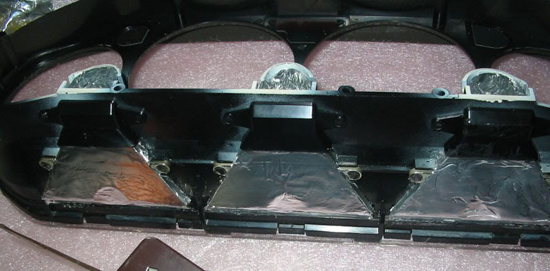
Here's what I was faced with:
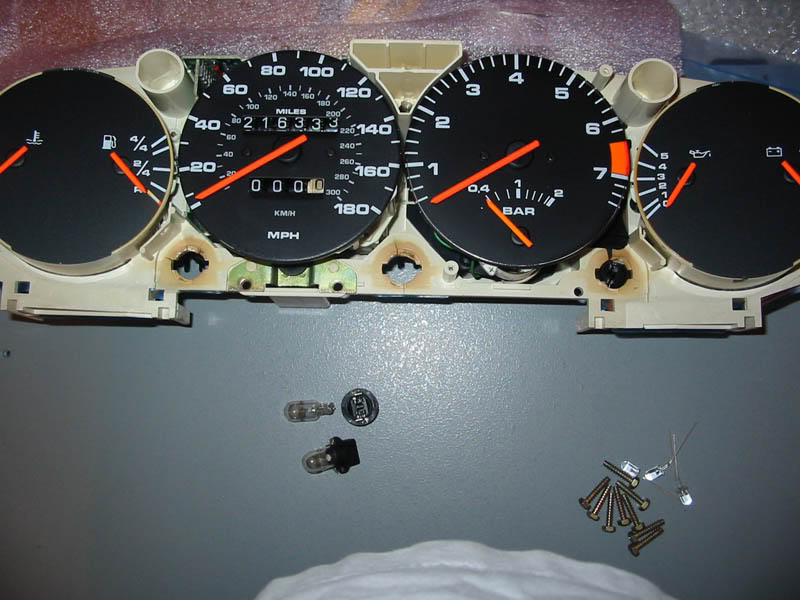
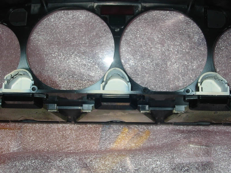
The instrument panel, with two of the three twist-out bulb holders removed. -The third one (on the far right) had actually MELTED the plastic to the point where I had to use BIG pliers to twist it out... further breaking the plastic as I went. -You can see the other two holes (center and left) are also brown from the heat. The plastic was brittle and you can also see cracks there. None of the bulbs came out easily, but the one on the right put up a BIG fight.
Also at the bottom of the picture, you can see the LEDs I was planning to use, next to the nine removed screws whcih held the front lens to the instrument panel.
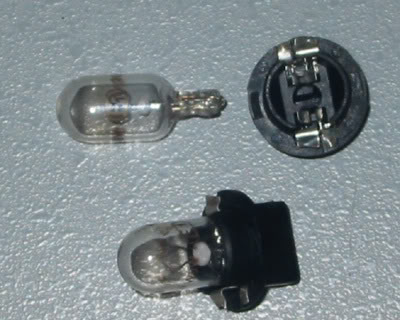
Here's a close-up of a bulb removed from the twist-base, and another one still installed in the twist-base.
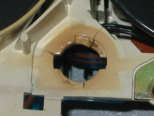
A close-up of the melted and cracked twist-lock bulb sockets:
...and a couple of gruesome close-ups...
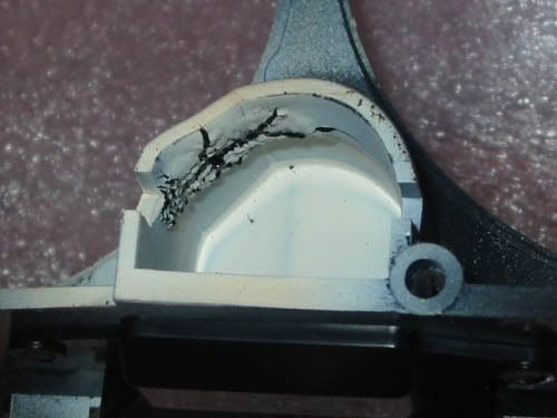
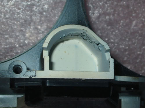
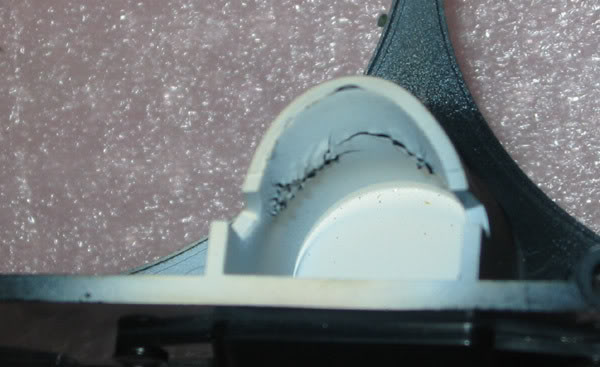
In addition, the heat from the bulbs had done some collateral damage to the bulb 'shrouds' which form part of the front assembly:
...some more gruesome close-ups just for good measure...
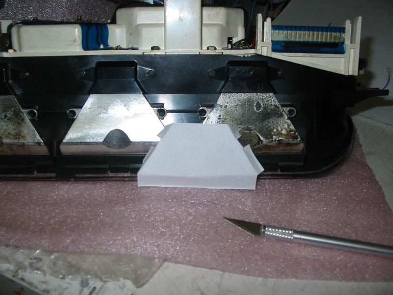
The melting and brittleness of the plastic was caused by the use of higher-wattage bulbs (5 Watt bulbs in each of the three sockets) which creates a LOT more heat than the plastic can tolerate. The main reason for the higher wattage seemed to be the fact that the silver coating had degraded on most of the light 'tunnels'.
I decided to use aluminium foil to re-silver the tunnels, so I started by cutting out a basic template from paper, using an exacto-knife.
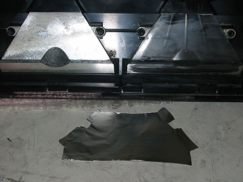
Then I cut out some (slightly-oversized) pieces of foil, to be attached "shiny-side-in".
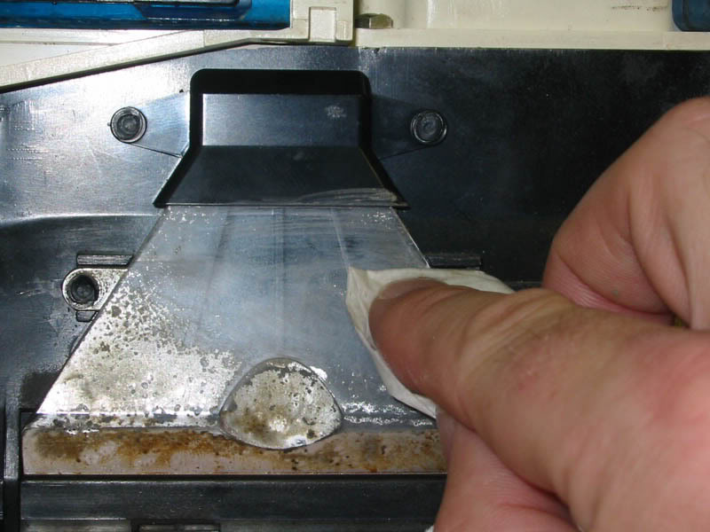
The old silver was removed using non-acetone nail polish remover:
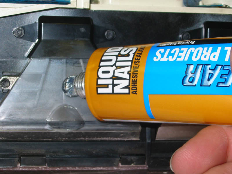
...and some clear adhesive was added. -"Liquid nails" small-project adhesive works great... make sure that you use the CLEAR stuff though, -it also comes in a murky-brown version which isn't much good for this purpose!
The adhesive was spread over the clear plastic on the bottom AND SIDES of the optic 'tunnel',
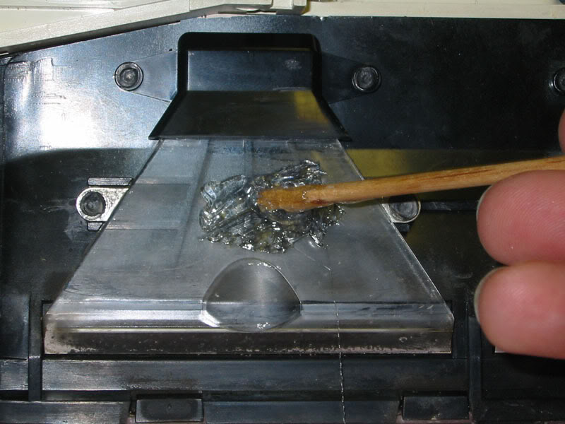
..then the foil was added. (note: The adhesive goes tacky fairly quickly, so have the foil cut out and ready to be affixed BEFORE you spread the adhesive on.)
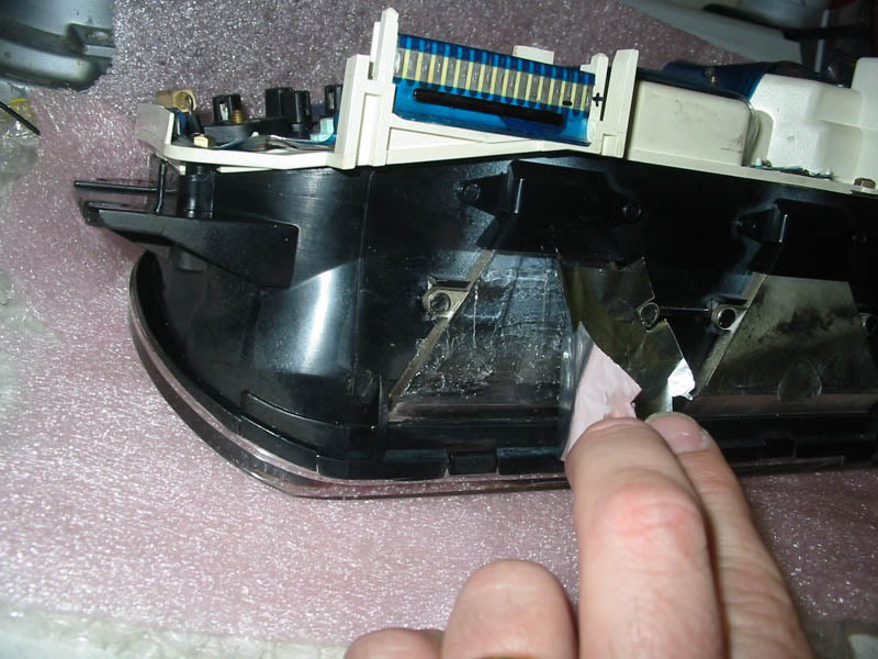
then the foil was rubbed down using a ball of paper towel, and the edges wre trimmed for neatness.
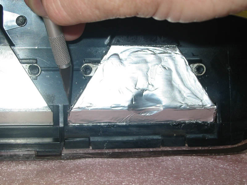
Afterwards, I added some oversized pieces of clear packing tape, to protect the foil from any scraping which may happen while trying to wrestle it back into the dashboard. I let this overhang the edges of the silver, to provide more adhesion as well as protection.
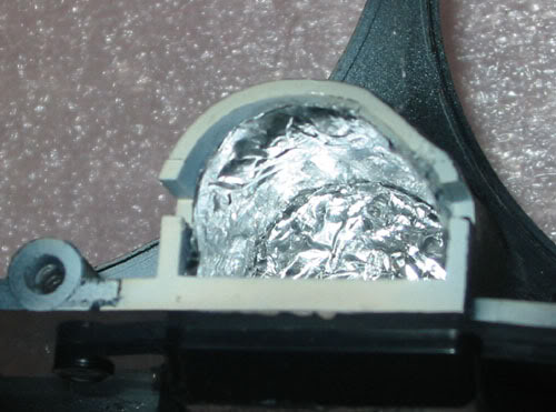
Now... to further help 'gather' any stray light and reflect it into the optic 'tunnel', I decided to silver the inside of the little 'bulb shrouds' on the front lens:
Here's a close up of one:
Now... SO much for re-silvering. On to the LED part.
My original intention had been to make soemthing which would re-use the twist-bases, so that it could be swapped-in easily. The sheer heat damage to the plastic AND to the contact area on the flexible blue circuit board on the back of the instrument panel meant that this was probably not going to work as I'd hoped... The bulbs had been intermittent for some time (go over a bump and one goes out, hit a pothole and another one lights up... go over a railroad crossing and enjoy your own "intrument-cluster-disco"!) and this was probably down to the heat damage to the contacts on the rear circuit 'board'.
I decided that I'd have to solder. There really wasn't any other say to keep things reliable, and I don't want to have to pull the instrument cluster every time I have intermittent lights... I want this fixed once, and fixed right.
So by hooking the cluster up to the car, turning in the lights, and probing with the multimeter, I confirmed that ALL THREE light sockets have their positive terminal at the LOWER EDGE of the cluster... -This is important with diodes, since they only conduct in one direction, and they are easily damaged from being reversed. It's therefore crucial that you know which way round to wire them.
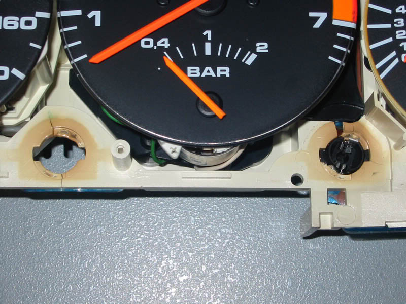
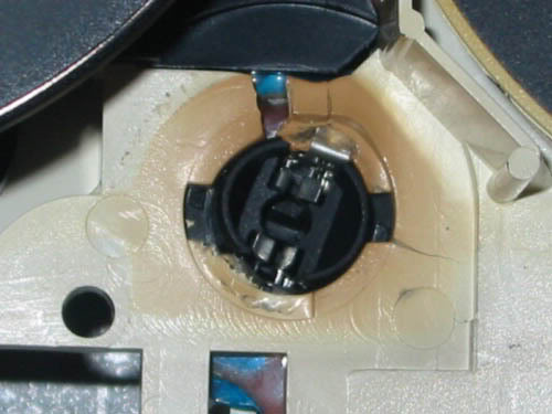
-Revisiting this piscure for a moment:
...you can see that I've marked two contacts "+" and "-" on one of the connectors on the rear of the cluster (the horizontal connector behind the voltmeter/oil pressure gauges). The two terminals nearest the CENTER of the cluster are the terminals which connect to all three dashboard lights. If you want to test the dash illumination on the bench, you can do so by applying power (a 9V battery is plenty to test LEDs with... it doesn't have to be the FULL 12 volts...) but with LEDs it's important to know which to connect to positive and which to negative, so I marked them with a permanent marker for my reference. -If you wish to mark them on your cluster for bench-testing, remember that the contact closest to the tachometer is POSITIVE, and the contact immediately next to it, is negative. (I put the negative mark NEXT to the contact to which it refers... don't be confused!)
Okay, I tried 2 x White 18,000mcd LEDs per bulb-location, running at 20mA nominal requires a 430Ω resistor to be wired in series.
Here's some shots of how it was laid out:
First the LEDs were wired in series, with the cathodes (the shorter of the two leads) facing the SAME direction, so the anode of one was twisted with the cathode of the other, then soldered, then the joint was clipped and covered with heat-shrink tubing.
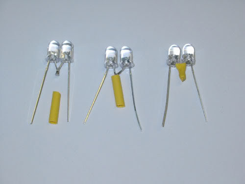
Then a 430Ω resistor was soldered in series, (I always solder it at the ANODE, so that I'll always remember that the resistor goes to the positive terminal... you can use whichever terminal you prefer, just make SURE that remember which is positive!) and the resistore and the solder joint were covered with heat-shrink tubing.
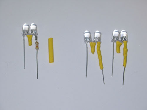
At this point, the series chain of two LEDs and a resistor can be tested using a 9-volt battery. Once you're happy that they work nicely, they can be put in place.
The LEDs need to be popped through the hole, and bent so that they point DOWNWARDS to the rectangular hole at the entrance to the optic 'tunnel'. -If you don't get what I mean, look at the bulb 'shrounds' in the front lens assembly, and see where the light exits at the bottom, into the tunnel... -Like this:
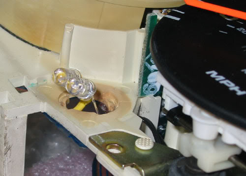
...a closer view:
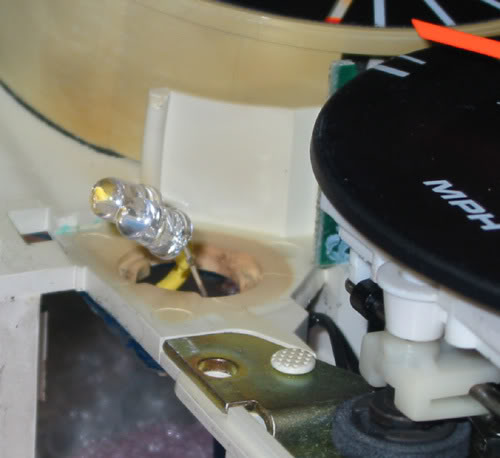
Around the back of the instrument cluster, you should be able to see how the leads need to be bent in order for the LEDs to 'sit' nicely against the 'window' into the optic 'tunnel'. Once you've got them arranged, you can solder them in place.
A word on soldering to the flexible circuit board contacts: don't keep the iron in contact with the contacts on the PCB for more than a SECOND. If you overheat the circuit board, it will start to melt, and the traces can seperate... don't think that a cooler iron will be safer: a cooler iron will need to be held on longer. -If your iron has a temerature control, use it on a nice HIGH setting, and work quickly. put a small blob of solder on the middle of each solder contact and LET IT COOL for at least twenty seconds before going back and applying more heat... work PATIENTLY and you should do no harm.
Also, 'tin' the two leads of your LED array with a little clean solder, and once everything is cool and ready place nicely, simply melt the solder quickly on ONE of the two contacts (either the upper or the lower) and allow it to weld with the lead. -the INSTANT the solder melts, REMOVE the iron, and don't be tempted to add any more heat or solder until it's cooled COMPLETELY. you don't want to melt the trace off the circuit board.
Once one is done, you can do the other... the you should have something looking like this:
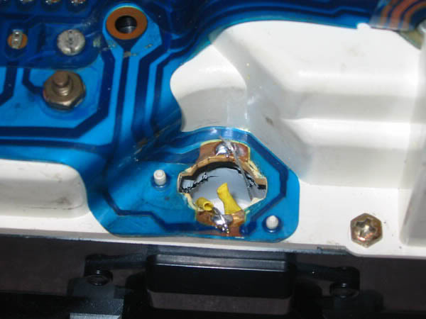
You can see the heat-shrinked lead with the resistor (on the positive leg) is soldered to the contact on the LOWER edge of the instrument panel, since that is the POSITIVE contact. DOUBLE ChECK your wiring before yo move on and do the other two bulb arrays.
That's it. Re-assemble the front lens assembly onto the instrumet cluster with the 9 screws, look that you don't 'trap' any of the LEDs in the closing gap when they go together, or they won't line up easily.
Once it's done, you can bench-test the illumination if you like (as mentioned earlier) and if everything looks A-OK, pop it back in the car.
Here's what the finished thing looks like in my car... VERY hard to take a picture that captures the illumination well, but here's a couple of (shaky, hand-held) 4-second exposures, in which I've tried to include the rest of the illumination (climate control etc... -still with the original incandescent bulbs... but not for long!!!) as a sort of light-level and color-temperature reference.
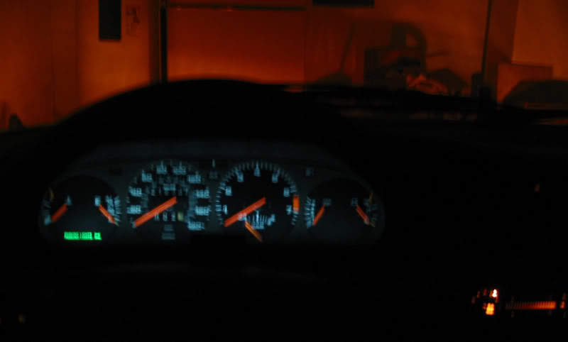
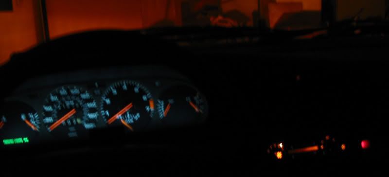
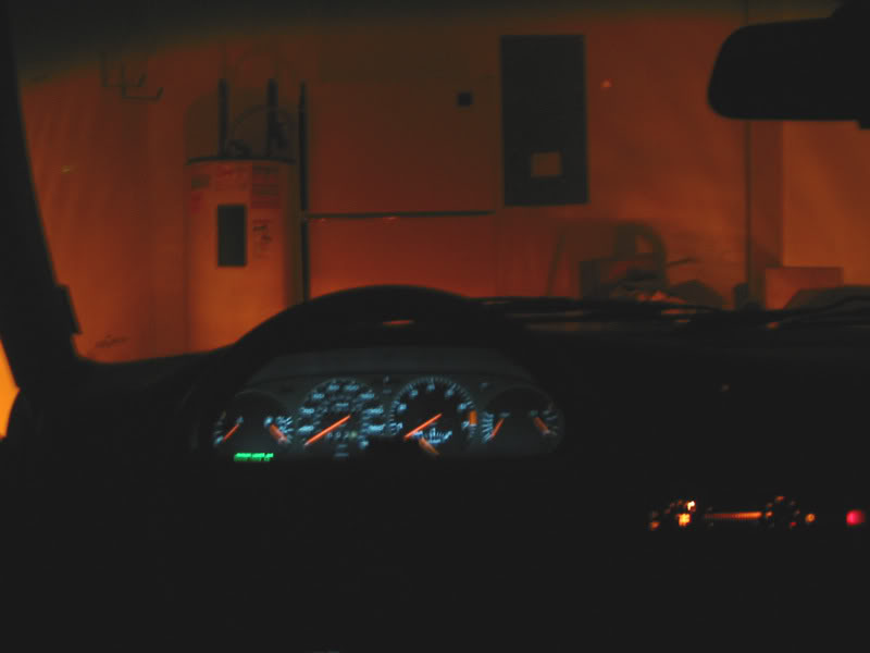
In these shots, I've used TWO double-LED chains per bulb location... because I actually like it pretty bright. They are wired in exactly the same way, just two identical chains of them through each hole. Both chains' positive lead goes to the lower contact, and both chains' negative lead connect to the upper contact.
If you want to add a splash of colour or play with the shade or tone of the dash illumination, without going ENTIRELY over to full blue, red, green or orange LEDs, you can request a color swatch from someone like "LEE Filters" who make lighting gel filters for the movie industry.

The color swatch will allow you to pick from about a hundred different gel filters, and once you've decided which one you like, (by holding it in front of an illuminated white LED) there's actually more than enough material in each swatch color sample to cut out a small rectangle and fix it over the 'window' to each optic tunnel. Thus you can have ANY shade you can imagine... "make the carpet match the drapes" kinda thing... -If you really want to get that ****. -Me, I just love the fact that i can SEE the darned gauges at night, and that they don't flicker and flash like a techno-rave every time I run over the reflectors between lanes!
Okay, that's it for now... If there's anything I haven't explained too well, Point it out, and I'll try and do better... Honestly, if you can solder, this is a piece of CAKE! -I bought a hundred LEDs and I have LOTS left over... I think I'll also do the clock and climate control next, then possibly the dome light... who knows where I'll stop!
Keith
The final result turned out pretty well I think, so I'm posting this in case anyone else wants to do their own version. -Intstrument panel was removed as per Clarks-garage, and once the odometer was fixed, I took a look at the lights.
Here's what I was faced with:
The instrument panel, with two of the three twist-out bulb holders removed. -The third one (on the far right) had actually MELTED the plastic to the point where I had to use BIG pliers to twist it out... further breaking the plastic as I went. -You can see the other two holes (center and left) are also brown from the heat. The plastic was brittle and you can also see cracks there. None of the bulbs came out easily, but the one on the right put up a BIG fight.
Also at the bottom of the picture, you can see the LEDs I was planning to use, next to the nine removed screws whcih held the front lens to the instrument panel.
Here's a close-up of a bulb removed from the twist-base, and another one still installed in the twist-base.
A close-up of the melted and cracked twist-lock bulb sockets:
...and a couple of gruesome close-ups...
In addition, the heat from the bulbs had done some collateral damage to the bulb 'shrouds' which form part of the front assembly:
...some more gruesome close-ups just for good measure...
The melting and brittleness of the plastic was caused by the use of higher-wattage bulbs (5 Watt bulbs in each of the three sockets) which creates a LOT more heat than the plastic can tolerate. The main reason for the higher wattage seemed to be the fact that the silver coating had degraded on most of the light 'tunnels'.
I decided to use aluminium foil to re-silver the tunnels, so I started by cutting out a basic template from paper, using an exacto-knife.
Then I cut out some (slightly-oversized) pieces of foil, to be attached "shiny-side-in".
The old silver was removed using non-acetone nail polish remover:
...and some clear adhesive was added. -"Liquid nails" small-project adhesive works great... make sure that you use the CLEAR stuff though, -it also comes in a murky-brown version which isn't much good for this purpose!
The adhesive was spread over the clear plastic on the bottom AND SIDES of the optic 'tunnel',
..then the foil was added. (note: The adhesive goes tacky fairly quickly, so have the foil cut out and ready to be affixed BEFORE you spread the adhesive on.)
then the foil was rubbed down using a ball of paper towel, and the edges wre trimmed for neatness.
Afterwards, I added some oversized pieces of clear packing tape, to protect the foil from any scraping which may happen while trying to wrestle it back into the dashboard. I let this overhang the edges of the silver, to provide more adhesion as well as protection.
Now... to further help 'gather' any stray light and reflect it into the optic 'tunnel', I decided to silver the inside of the little 'bulb shrouds' on the front lens:
Here's a close up of one:
Now... SO much for re-silvering. On to the LED part.
My original intention had been to make soemthing which would re-use the twist-bases, so that it could be swapped-in easily. The sheer heat damage to the plastic AND to the contact area on the flexible blue circuit board on the back of the instrument panel meant that this was probably not going to work as I'd hoped... The bulbs had been intermittent for some time (go over a bump and one goes out, hit a pothole and another one lights up... go over a railroad crossing and enjoy your own "intrument-cluster-disco"!) and this was probably down to the heat damage to the contacts on the rear circuit 'board'.
I decided that I'd have to solder. There really wasn't any other say to keep things reliable, and I don't want to have to pull the instrument cluster every time I have intermittent lights... I want this fixed once, and fixed right.
So by hooking the cluster up to the car, turning in the lights, and probing with the multimeter, I confirmed that ALL THREE light sockets have their positive terminal at the LOWER EDGE of the cluster... -This is important with diodes, since they only conduct in one direction, and they are easily damaged from being reversed. It's therefore crucial that you know which way round to wire them.
-Revisiting this piscure for a moment:
...you can see that I've marked two contacts "+" and "-" on one of the connectors on the rear of the cluster (the horizontal connector behind the voltmeter/oil pressure gauges). The two terminals nearest the CENTER of the cluster are the terminals which connect to all three dashboard lights. If you want to test the dash illumination on the bench, you can do so by applying power (a 9V battery is plenty to test LEDs with... it doesn't have to be the FULL 12 volts...) but with LEDs it's important to know which to connect to positive and which to negative, so I marked them with a permanent marker for my reference. -If you wish to mark them on your cluster for bench-testing, remember that the contact closest to the tachometer is POSITIVE, and the contact immediately next to it, is negative. (I put the negative mark NEXT to the contact to which it refers... don't be confused!)
Okay, I tried 2 x White 18,000mcd LEDs per bulb-location, running at 20mA nominal requires a 430Ω resistor to be wired in series.
Here's some shots of how it was laid out:
First the LEDs were wired in series, with the cathodes (the shorter of the two leads) facing the SAME direction, so the anode of one was twisted with the cathode of the other, then soldered, then the joint was clipped and covered with heat-shrink tubing.
Then a 430Ω resistor was soldered in series, (I always solder it at the ANODE, so that I'll always remember that the resistor goes to the positive terminal... you can use whichever terminal you prefer, just make SURE that remember which is positive!) and the resistore and the solder joint were covered with heat-shrink tubing.
At this point, the series chain of two LEDs and a resistor can be tested using a 9-volt battery. Once you're happy that they work nicely, they can be put in place.
The LEDs need to be popped through the hole, and bent so that they point DOWNWARDS to the rectangular hole at the entrance to the optic 'tunnel'. -If you don't get what I mean, look at the bulb 'shrounds' in the front lens assembly, and see where the light exits at the bottom, into the tunnel... -Like this:
...a closer view:
Around the back of the instrument cluster, you should be able to see how the leads need to be bent in order for the LEDs to 'sit' nicely against the 'window' into the optic 'tunnel'. Once you've got them arranged, you can solder them in place.
A word on soldering to the flexible circuit board contacts: don't keep the iron in contact with the contacts on the PCB for more than a SECOND. If you overheat the circuit board, it will start to melt, and the traces can seperate... don't think that a cooler iron will be safer: a cooler iron will need to be held on longer. -If your iron has a temerature control, use it on a nice HIGH setting, and work quickly. put a small blob of solder on the middle of each solder contact and LET IT COOL for at least twenty seconds before going back and applying more heat... work PATIENTLY and you should do no harm.
Also, 'tin' the two leads of your LED array with a little clean solder, and once everything is cool and ready place nicely, simply melt the solder quickly on ONE of the two contacts (either the upper or the lower) and allow it to weld with the lead. -the INSTANT the solder melts, REMOVE the iron, and don't be tempted to add any more heat or solder until it's cooled COMPLETELY. you don't want to melt the trace off the circuit board.
Once one is done, you can do the other... the you should have something looking like this:
You can see the heat-shrinked lead with the resistor (on the positive leg) is soldered to the contact on the LOWER edge of the instrument panel, since that is the POSITIVE contact. DOUBLE ChECK your wiring before yo move on and do the other two bulb arrays.
That's it. Re-assemble the front lens assembly onto the instrumet cluster with the 9 screws, look that you don't 'trap' any of the LEDs in the closing gap when they go together, or they won't line up easily.
Once it's done, you can bench-test the illumination if you like (as mentioned earlier) and if everything looks A-OK, pop it back in the car.
Here's what the finished thing looks like in my car... VERY hard to take a picture that captures the illumination well, but here's a couple of (shaky, hand-held) 4-second exposures, in which I've tried to include the rest of the illumination (climate control etc... -still with the original incandescent bulbs... but not for long!!!) as a sort of light-level and color-temperature reference.
In these shots, I've used TWO double-LED chains per bulb location... because I actually like it pretty bright. They are wired in exactly the same way, just two identical chains of them through each hole. Both chains' positive lead goes to the lower contact, and both chains' negative lead connect to the upper contact.
If you want to add a splash of colour or play with the shade or tone of the dash illumination, without going ENTIRELY over to full blue, red, green or orange LEDs, you can request a color swatch from someone like "LEE Filters" who make lighting gel filters for the movie industry.
The color swatch will allow you to pick from about a hundred different gel filters, and once you've decided which one you like, (by holding it in front of an illuminated white LED) there's actually more than enough material in each swatch color sample to cut out a small rectangle and fix it over the 'window' to each optic tunnel. Thus you can have ANY shade you can imagine... "make the carpet match the drapes" kinda thing... -If you really want to get that ****. -Me, I just love the fact that i can SEE the darned gauges at night, and that they don't flicker and flash like a techno-rave every time I run over the reflectors between lanes!
Okay, that's it for now... If there's anything I haven't explained too well, Point it out, and I'll try and do better... Honestly, if you can solder, this is a piece of CAKE! -I bought a hundred LEDs and I have LOTS left over... I think I'll also do the clock and climate control next, then possibly the dome light... who knows where I'll stop!
Keith
 12-08-2007, 05:29 PM
#4
Rennlist Member
Great writeup!
I know I was one of the guys nagging you to get this done ASAP, and I thank you very much! Fortunately i've been busy so haven't had the time to take apart the cluster.
I do have a couple questions for you, especially because electrical circuits are not my forte:
1) what type of LED did you use (voltage, etc) and where did you get them?
2) you ended up using 6 LEDs, correct?
3) Why did you decide to wire the LEDs in series and not parallel? If in parallel, wouldn't that allow them to keep full voltage and possibly make things brighter? At least, perhaps the dimmer would work better?
Thanks!
12-08-2007, 06:12 PM
#6
Burning Brakes
Thread Starter
Join Date: Mar 2006
Location: Orlando,FL (formerly UK)
Posts: 1,215
Likes: 0
Received 0 Likes
on
0 Posts
>>what type of LED did you use (voltage, etc) and where did you get them?
I used 18000mCd white, with front-lensing. You can find them all over eBay... about $10 for a hundred of them... plus shipping, I think I paid $5 shipping, so they came out at 15 cents each, and they wre shipped with 100 x 500Ω resistors which allow you to use them singly... very handy.
>>2) you ended up using 6 LEDs, correct?
I actually used twelve... I doubled up the quantities in the photographed part of the writeup.
>>3) Why did you decide to wire the LEDs in series and not parallel? If in parallel, wouldn't that allow them to keep full voltage and possibly make things brighter? At least, perhaps the dimmer would work better?
Hmmm... it's a little tricky to explain but I'll give it a go:
LEDs have a forward voltage rating. In the case of these LEDs, it's about 3Volts. In order to get them to work on 12 volts, you have to use a series resistor to 'waste' the excess volts and limit the current. Using a 500Ω series resistor means that 3 volts drop across the LED, and the remaining 9 volts across the resistor.
Ohms law: V=IxR, or volts = current times resistance... therefore Current = Volts divided by resistance. 9/500=0.018 Amps, or 18 milliamps. -Perfect! -since these are nominally rated at 20milliamps. (30mA absolute maximum, 20mA recommended continuous maximum.)
LEDs are brightened or dimmed by increasing the CURRENT through them, NOT the voltage across them, becasue they want to "clamp" the voltage at a fixed level... in this case about 3 volts.
If you wire two LEDs in parallel, one will 'hog' more of the current. You have to have resistors in series with every leg to distribute the current evenly... but you don't have to use four x 500Ω resistors... if you wire two as a series pair, the total forward voltage becomes about 6volts... just drop 6 volts now instead of 9 volts, and for the SAME current drain on the battery (a total of 18mA).
Now we COULD wire 4 LEDs in series, and have 4 times the light output woth NO increase in total current, but then the total forward drop would be about 12 volts... uncomfortably close to our supply voltage, so a small fluctuation (turning on the A/C, etc) that dropped the supply down -for example- to about 11.5Volts, which might cause a 'normal' bulb to dim slightly would likely be enough for our chain-of-four to shut off completely. -Remember, each LED needs at LEAST 3volts to begin conduction.
In another thread I posted a video of LEDs dimming and going into shutdown with a variable voltage source... You can see that the chain of two dims and shuts down sooner than the single LED... the more you add, the more suddenly they shut down.
Keith
Last edited by VWaddict; 12-08-2007 at 06:29 PM.
12-08-2007, 06:19 PM
#7
Burning Brakes
Thread Starter
Join Date: Mar 2006
Location: Orlando,FL (formerly UK)
Posts: 1,215
Likes: 0
Received 0 Likes
on
0 Posts
Oh, another onservation which you can easily test:
With the instrmuent cluster unplugged, you can see how the rheostat ceases to dim the REST of the light bulbs efficiently... the climate control etc. A crude way to make this work would be to 'mimic' the load which is usually provided by the lights would be to wire a 25-Watt 15-ohm resistor with one end of the resstor in the llumination line after the rheostat, the other connected to ground...
Your dimmer would work on both the LEDs and the rest of the lights, but only because you'd 'undone' all of the current-saving that the LEDs provide... sort of like buying a car that gets better gas mileage, and then pouring gas down the drain so that you still consume the same amount...
I'm working on a small but interesting circuit to add which would use the factory rheostat, but NOT so wastefully... I'll keep everyone posted.
Here's the LED seller's eBay store:
http://stores.ebay.com/HKJE-Led-Lamp-Center
I bought the 100 x 18,000mcd 5mm package... -Oh, I actually see that it was $3.99 and $10 for shipping , but whatever, it's still under 15 cents each, including shipping.
If you really want to light-em up bright, they also sell 55,000mcd 5mm LEDs, about three times the brightness for $9.99...
Keith
Trending Topics
12-08-2007, 06:30 PM
#8
Rennlist Member
Man that's an awesome write up. Just like a bought one!
12-08-2007, 06:58 PM
#9
Rennlist Member
Hmmm very interesting, and I see what you're referring to. Another question tho -- how does a 12V LED differ from a standard 3V LED? Do they have a resistor built in?
So what would you recommend? 55cd is three times that of the ones you bought. Seems a bit bright to me, but hypothetically if I went w/ the 55cd units, I would probably not bother wiring two in series. If this is the case, would I need a larger resistor?
So what would you recommend? 55cd is three times that of the ones you bought. Seems a bit bright to me, but hypothetically if I went w/ the 55cd units, I would probably not bother wiring two in series. If this is the case, would I need a larger resistor?
12-08-2007, 07:42 PM
#10
Burning Brakes
Thread Starter
Join Date: Mar 2006
Location: Orlando,FL (formerly UK)
Posts: 1,215
Likes: 0
Received 0 Likes
on
0 Posts
If you buy an off-the-shelf bulb replacement, it wil have a resistor built-in. -If it's marked "unpolarised" then it additionally has a rectifier built in, which allows you to put it in "the wrong way round" and have it still work.
Pretty much all Leds that I can think of right now have a fixed forward voltage in the order of 4volts or less (it varies with the chemicals used to make the LED... a typical red LED is usually Gallium Arsenide, and has a 2Volts forward drop). To save people doing lots of math and having to buy resistors, they sell "12V LED bulb replacements" which have the other stuff inside them already.
If you do it yourself, you can do tle climate control, the clock, the isntrumentation, the trunk light, the license-plate lights, the reversing lights and the dome light and even that single tiny little one under the dash trim which illuminates the "defrost" for the same or less than what most people will pay for three bulbs to do the three instrument panel lights...
Hmmm... I have these three twist-bases here that I'm not going to use... maybe I should make some "plug-n-play" 4-LED clusters... -It's a thought!
Keith
12-08-2007, 08:54 PM
#12
Burning Brakes
Thread Starter
Join Date: Mar 2006
Location: Orlando,FL (formerly UK)
Posts: 1,215
Likes: 0
Received 0 Likes
on
0 Posts
12-08-2007, 09:24 PM
#13
Instructor

Join Date: Oct 2005
Location: Boynton Beach, Florida
Posts: 140
Likes: 0
Received 0 Likes
on
0 Posts
This company sells various automotive LED styles. They also have a voltage regulator to keep the LEDs from burning out.
http://www.42draftdesigns.com/catego...rfectmatch.htm
http://www.42draftdesigns.com/catego...rfectmatch.htm
12-08-2007, 10:06 PM
#14
Burning Brakes
Thread Starter
Join Date: Mar 2006
Location: Orlando,FL (formerly UK)
Posts: 1,215
Likes: 0
Received 0 Likes
on
0 Posts
Yep, that's Evan's company... (2KJettaGuy on VWVortex) I was talking with him some time ago about building a replacement for the (plastic) window regulator clip for the MkIV VW's, then VW came out with a cast metal replacement.
The "power regulator" as they call it (note, it ISN'T a voltage regulator) is actually four constant current sources in a box. -A CCS works well for PWM-dimmed illumination systems (like the VW MkIV series) but not well for voltage-dimmed devices. -Basically a CCS is a 'self-adjusting' series resistance to allow you to serially daisy-chain and maintain a constant amount of current through the LEDs when they're lit. (the appearance of dimming is achieved by varying the on-time-to-off-time ratio). A CCS is widely tolerant of voltage swings, but rheostat dimming is absolutely negated by a CCS.
42 draft designs is a great company, though ratherVW-centric. Evan's a great bloke.
Keith
12-08-2007, 11:34 PM
#15
Defending the Border
Rennlist Member
Rest In Peace
Rennlist Member
Rest In Peace
Outstanding Keith! I used aluminized foil tape to replace the reflectors coating.
Since my lamp sockets are in good shape, I think I'll jsut mount the LED assbys to them.
Since my lamp sockets are in good shape, I think I'll jsut mount the LED assbys to them.
Last edited by ibkevin; 12-08-2007 at 11:34 PM. Reason: typo