Seat adjuster fix-How To
 09-29-2013, 08:56 PM
#1
Rennlist Member
Thread Starter
You may notice one day that your formerly rock solid seat now shifts back and forth under braking and acceleration. I've had this issue for a while now and finally decided to tackle getting it fixed. Here's how to remedy that problem.
To do the repair you will need the following:
#2 and #3 Phillips screw driver
Impact screwdriver w/#3 Phillips bit
Small hammer
3/8" drive ratchet
4mm Allen socket
small Straight screwdriver
small locking pliers (aka Vise Grips)
(2) 17mm open-end wrench
rags
solvent
all purpose grease
(24) 1/2" i.d. x 3/4" o.d. nylon washer
Remove the seat from the car and place it on a suitable work space on it's back.
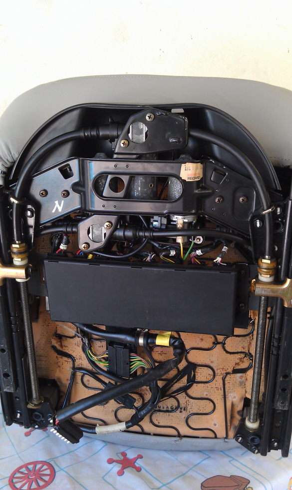
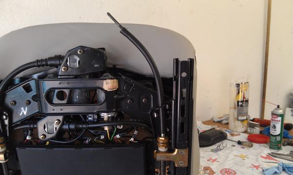
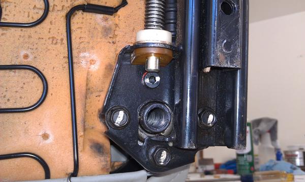
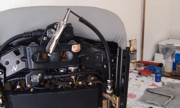
Here is the bottom of my 1990 8-way w/memory driver side seat. Others are similar. The two fore/aft adjuster screws are visible running down both sides.
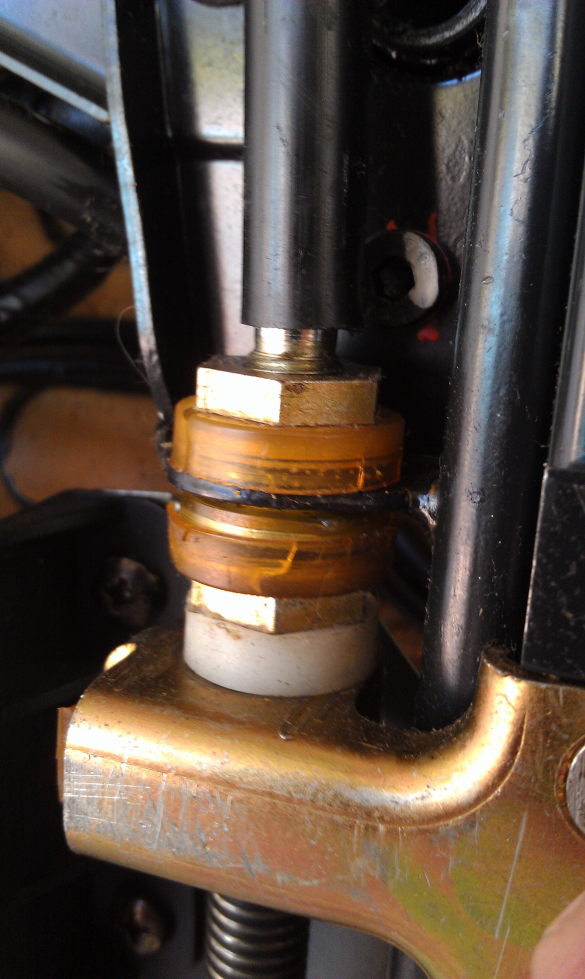
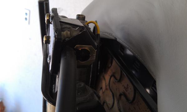
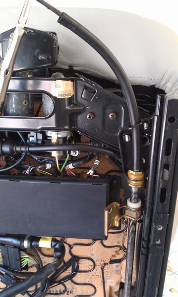
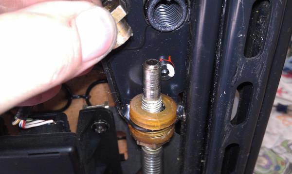
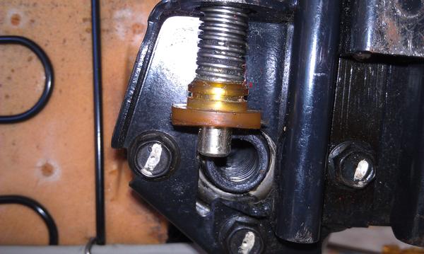
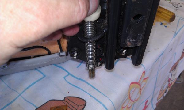
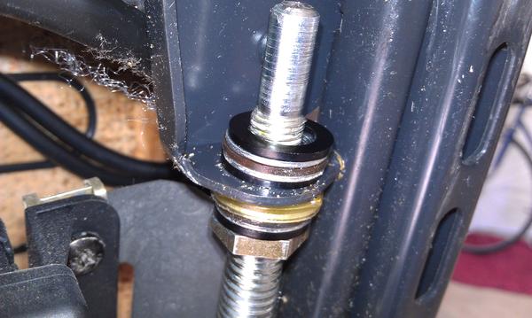
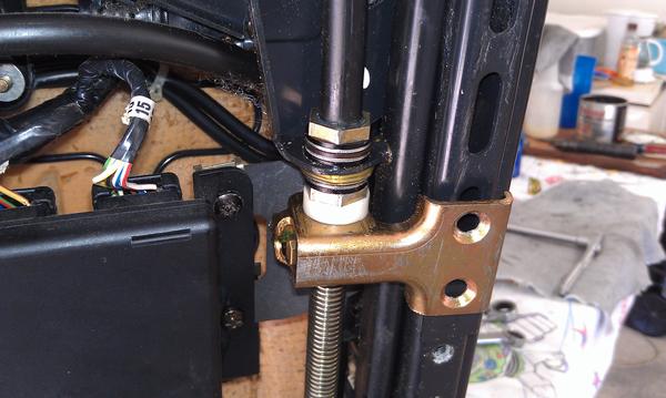
Here's a close up of the offending parts on one side.
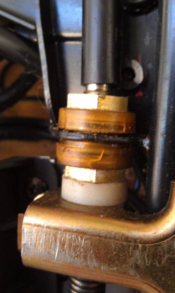
Here's the other side. Those yellowed plastic bits are the plastic cases for thrust bearings on the adjuster screws. When these come apart they allow play into the adjuster screw system and the seat starts clunking back and forth when braking or accelerating hard. We will be removing these adjuster screws and the deteriorated plastic so we can install new plastic spacers and eliminate the movement.
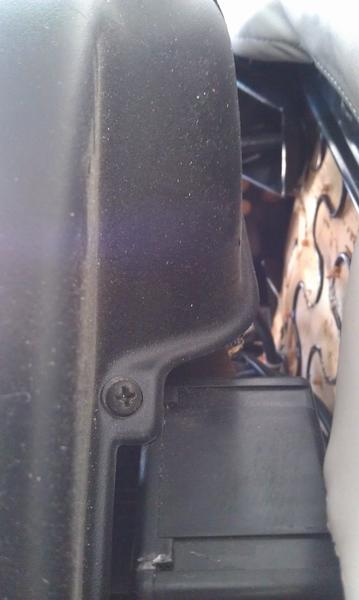
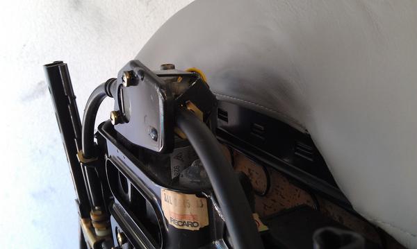
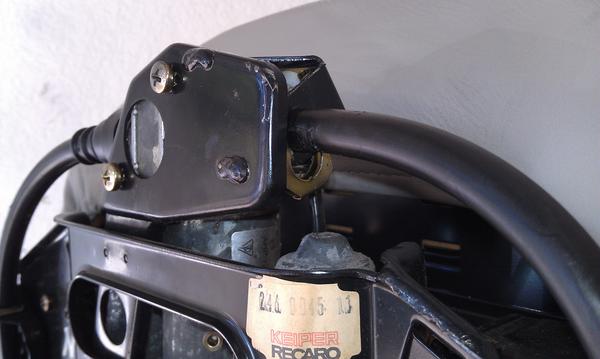
First, remove the front motor cover by removing the two securing screws. Here's one. The other is on the opposite side of the cover.
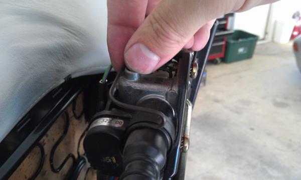
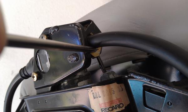
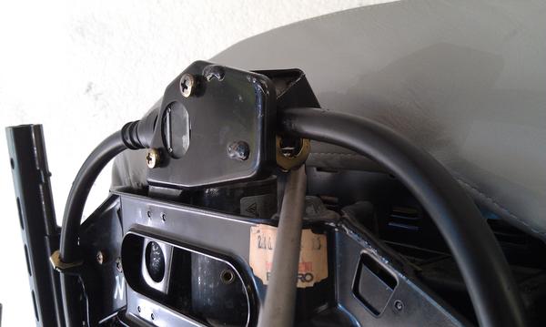
To remove the retaining clip for the potentiometer-side drive cable rotate the clip toward the bottom of the seat...
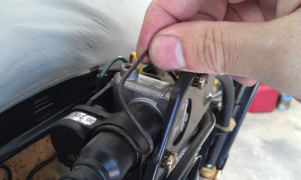
then tilt the right side of the clip toward the left off of the motor housing
then remove the clip.
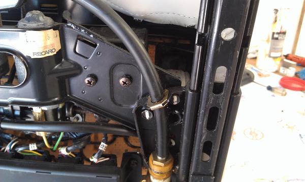
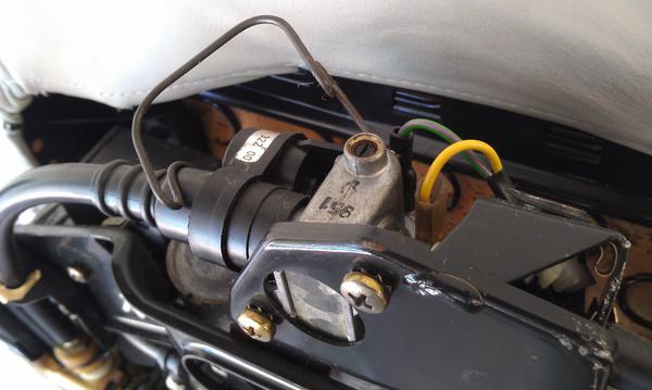
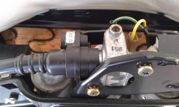
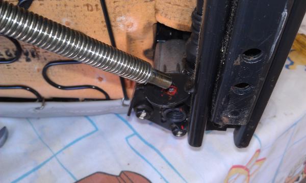
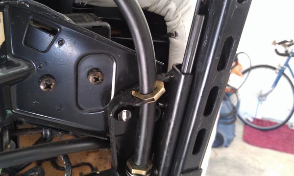
Next we need to remove the drive cable housing retainers here
and here so we can remove the drive cable.
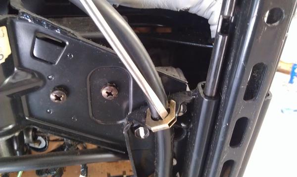
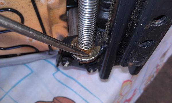
Use a small screwdriver to pry the clips loose from the housing at the adjuster screw
and at the manual seat adjuster drive.
You can leave the clips on the metal or remove them completely.
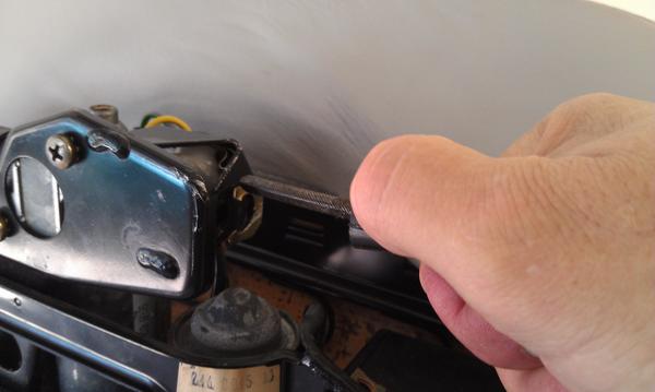
Grasp the cable housing and withdraw the cable from the manual seat adjustment drive.
To do the repair you will need the following:
#2 and #3 Phillips screw driver
Impact screwdriver w/#3 Phillips bit
Small hammer
3/8" drive ratchet
4mm Allen socket
small Straight screwdriver
small locking pliers (aka Vise Grips)
(2) 17mm open-end wrench
rags
solvent
all purpose grease
(24) 1/2" i.d. x 3/4" o.d. nylon washer
Remove the seat from the car and place it on a suitable work space on it's back.
Here is the bottom of my 1990 8-way w/memory driver side seat. Others are similar. The two fore/aft adjuster screws are visible running down both sides.
Here's a close up of the offending parts on one side.
Here's the other side. Those yellowed plastic bits are the plastic cases for thrust bearings on the adjuster screws. When these come apart they allow play into the adjuster screw system and the seat starts clunking back and forth when braking or accelerating hard. We will be removing these adjuster screws and the deteriorated plastic so we can install new plastic spacers and eliminate the movement.
First, remove the front motor cover by removing the two securing screws. Here's one. The other is on the opposite side of the cover.
To remove the retaining clip for the potentiometer-side drive cable rotate the clip toward the bottom of the seat...
then tilt the right side of the clip toward the left off of the motor housing
then remove the clip.
Next we need to remove the drive cable housing retainers here
and here so we can remove the drive cable.
Use a small screwdriver to pry the clips loose from the housing at the adjuster screw
and at the manual seat adjuster drive.
You can leave the clips on the metal or remove them completely.
Grasp the cable housing and withdraw the cable from the manual seat adjustment drive.

The following 2 users liked this post by ammonman:
English Bob (02-13-2022),
Peter F (09-30-2022)
09-29-2013, 09:19 PM
#2
Rennlist Member
Thread Starter
Leave the drive cable attached to the adjuster screw for now.
Now remove the two Phillips head screws that hold the adjuster drive plate to the seat slide rail. You might need to use a hand impact driver to get them started as they appear to have had thread locking compound applied at the factory. Remove both screws using a #3 Phillips.
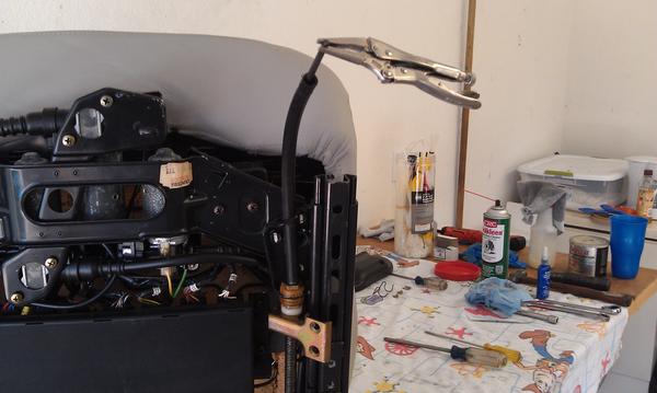
Gently clamp a small pair of locking pliers onto the square drive end of the drive cable.
Use the locking pliers as a handle to turn the drive cable and run the adjuster nut down the adjuster screw away from the upper adjuster screw mount. Give your self 2"-3" clearance.
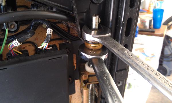
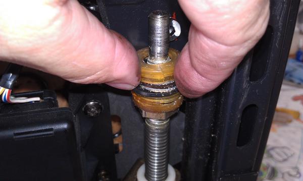
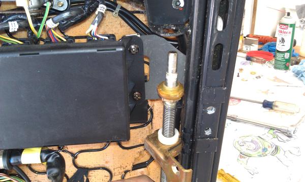
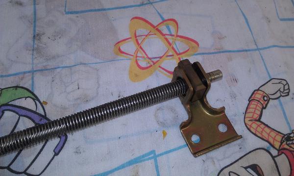
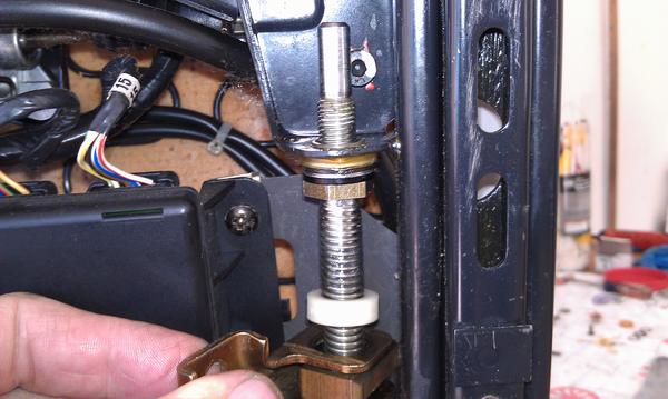
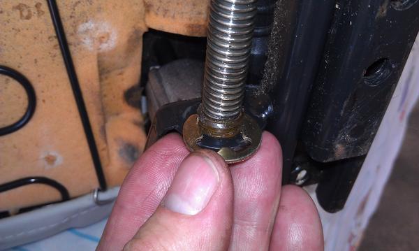
Using two 17mm open end wrenches unscrew the retaining nut from the top of the adjuster screw. This nut also seems to have had locking compound applied.
As the upper retaining nut unscrews it will start hitting on the socket head screw holding the front height adjuster unit to the seat frame. This is OK as you can continue to turn the lower retaining nut, which will turn the whole adjuster shaft and finish unscrewing the upper retaining nut.
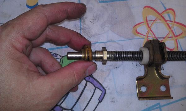
Remove the retaining nut
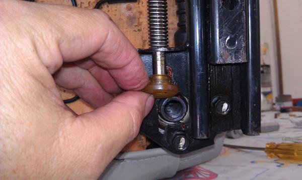
Followed by the plastic bits
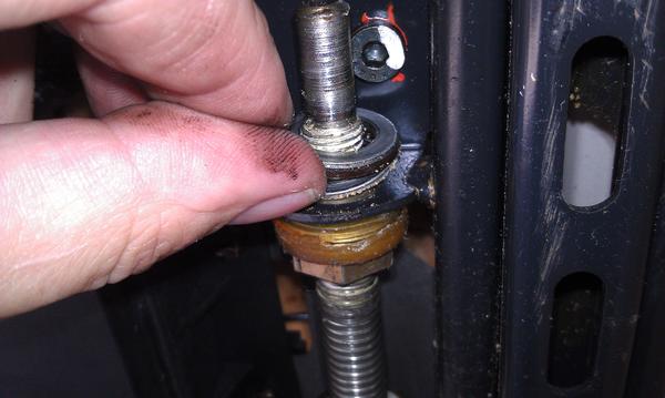
and the upper thrust bearing.
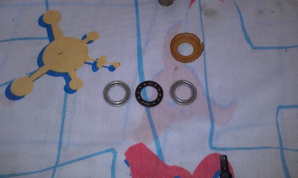
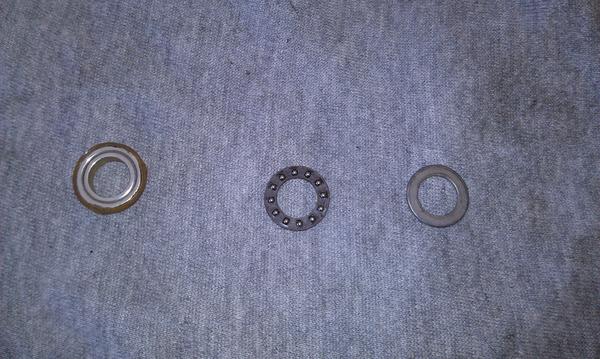
Here's the two thrust bearing washers, the bearing cage and *****, and what's left of the plastic housing.
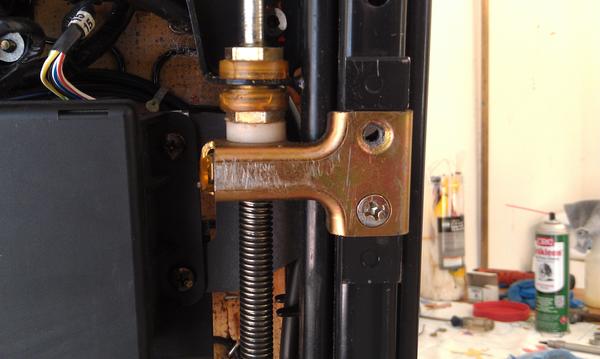
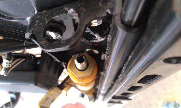
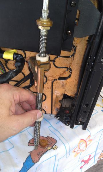
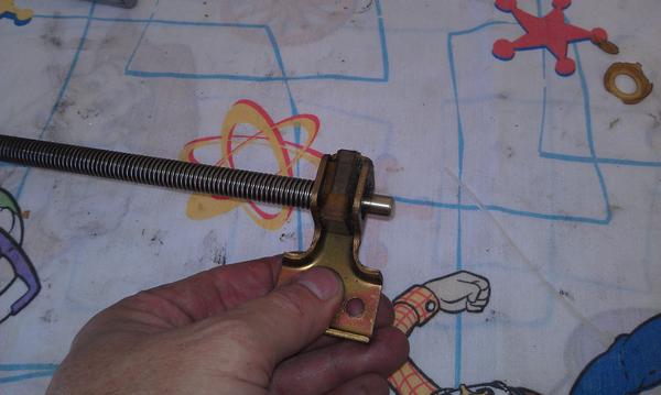
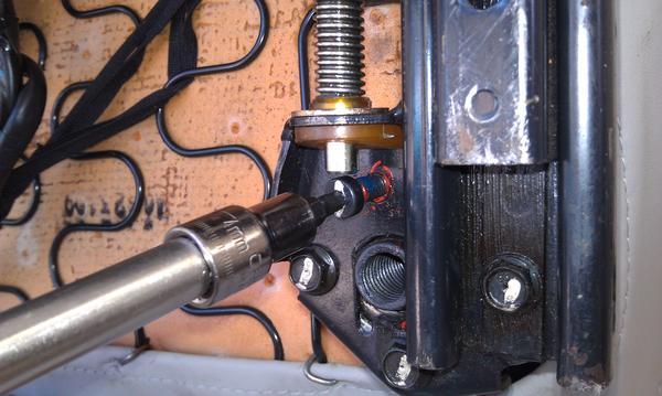
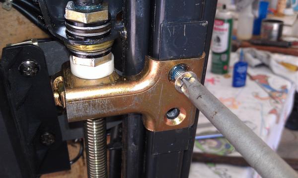
Here's the lower end of the adjuster rod. Remove the socket head screw to allow the plastic carrier bushing that locates this end of the adjuster rod to come off.
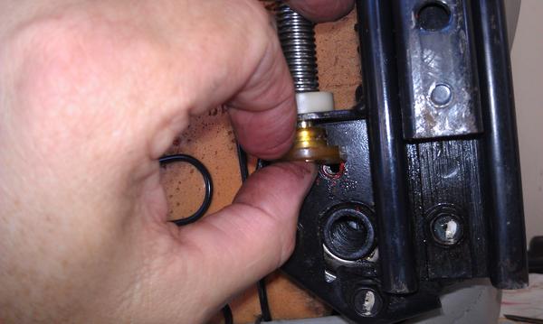
Use a small straight screwdriver to remove the E-clip that holds the lower carrier bushing.
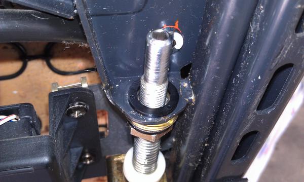
Lower the adjuster screw
and remove the carrier bushing.
Lower the adjuster screw further
The following users liked this post:
Peter F (09-30-2022)
09-29-2013, 09:46 PM
#3
Rennlist Member
Thread Starter
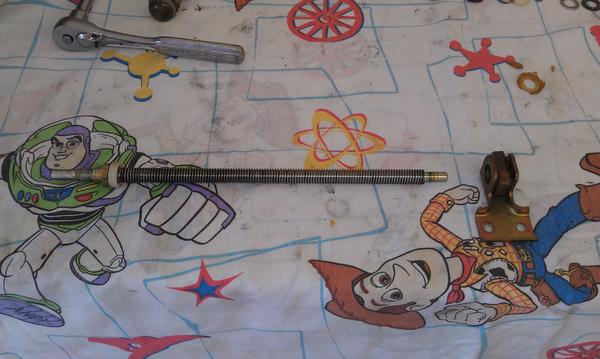
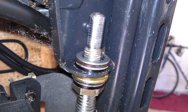
Lower the adjuster screw
Until the upper end of the adjuster screw is free of the mount
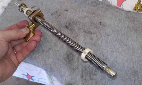
You should now have the adjusting screw and nut free from the seat.
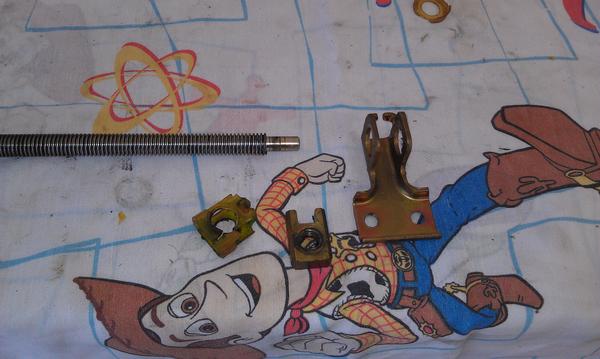
Remove the lower travel stop bumper
and the other thrust bearing
screw the adjuster nut and plate off the adjuster screw.
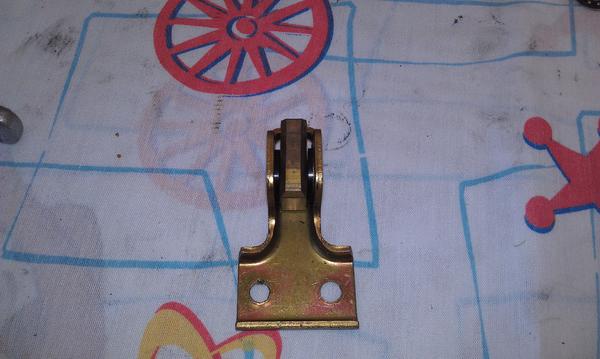
Once the adjuster plate/nut is off the screw remove the upper adjuster stop bumper bushing.
Note: Help from Woody and Buzz not required but strongly recommended.
The adjuster nut is cushioned in the adjuster bracket by a plastic surround. This plastic is also deteriorated so I opted to replace it with plastic washers as well.
The washers I used didn't fit very snug.
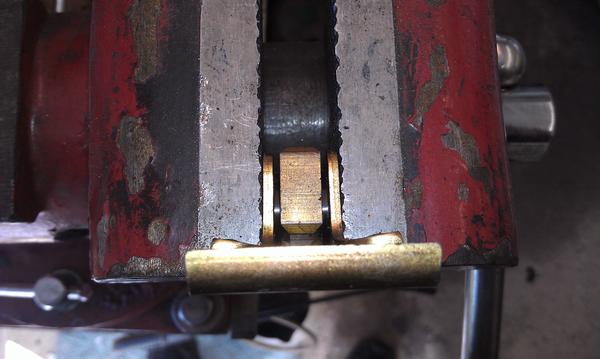
so I clamped the bracket with the nut and washers in a vise and compressed the clamp enough to snugly hold the washers in place.
Clean the adjuster screw of all old grease and apply fresh grease of your choice.
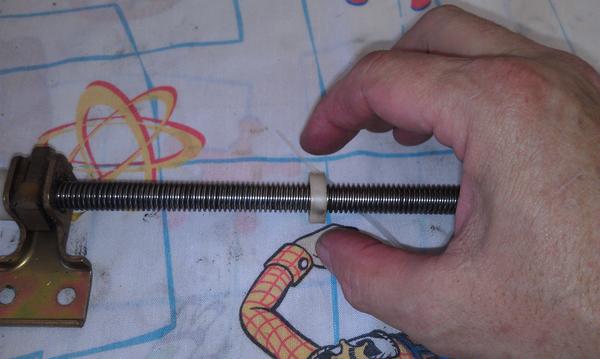
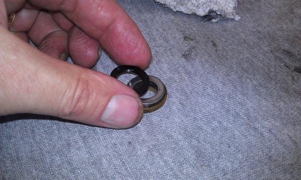
Notice the adjuster stop bumpers are beveled on one side.
The bevel on both bumpers faces toward the back of the seat when installed on the adjuster screw.
Slip the upper bumper onto the adjuster screw with the beveled side facing the bottom of the screw.
Thread the adjuster bracket back on to the adjuster screw
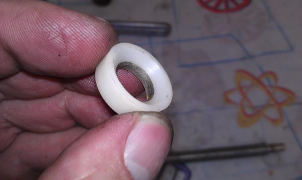
Clean the thrust bearing parts and apply fresh grease of your choice. Notice each washer is grooved to give the ***** a "race" to ride in.
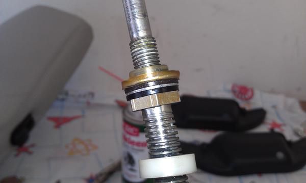
Here is one thrust bearing assembled. I'm adding one washer to take up the space of the deteriorated plastic. The other side of the bearing assembly has a bit of the original plastic in place as it has a centering ring. This plastic will eventually give out but I'm curious to see how much longer it lasts so I re-used it on this bearing set.
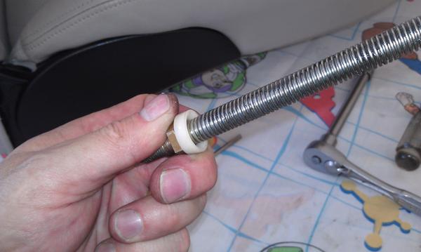
Slip the thrust bearing back on the upper end of the adjuster screw.
Until the upper end of the adjuster screw is free of the mount
You should now have the adjusting screw and nut free from the seat.
Remove the lower travel stop bumper
and the other thrust bearing
screw the adjuster nut and plate off the adjuster screw.
Once the adjuster plate/nut is off the screw remove the upper adjuster stop bumper bushing.
Note: Help from Woody and Buzz not required but strongly recommended.
The adjuster nut is cushioned in the adjuster bracket by a plastic surround. This plastic is also deteriorated so I opted to replace it with plastic washers as well.
The washers I used didn't fit very snug.
so I clamped the bracket with the nut and washers in a vise and compressed the clamp enough to snugly hold the washers in place.
Clean the adjuster screw of all old grease and apply fresh grease of your choice.
Notice the adjuster stop bumpers are beveled on one side.
The bevel on both bumpers faces toward the back of the seat when installed on the adjuster screw.
Slip the upper bumper onto the adjuster screw with the beveled side facing the bottom of the screw.
Thread the adjuster bracket back on to the adjuster screw
Clean the thrust bearing parts and apply fresh grease of your choice. Notice each washer is grooved to give the ***** a "race" to ride in.
Here is one thrust bearing assembled. I'm adding one washer to take up the space of the deteriorated plastic. The other side of the bearing assembly has a bit of the original plastic in place as it has a centering ring. This plastic will eventually give out but I'm curious to see how much longer it lasts so I re-used it on this bearing set.
Slip the thrust bearing back on the upper end of the adjuster screw.
The following users liked this post:
Peter F (09-30-2022)
09-29-2013, 10:14 PM
#4
Rennlist Member
Thread Starter
slip the lower adjuster stop bumper bushing on to the bottom of the adjuster screw, making sure the beveled side is facing the bottom end of the screw.
Insert the bottom end of the adjuster screw into the mounting bracket far enough to allow the upper end of the adjuster screw the slip up into the upper mounting bracket.
Slip the lower carrier bushing on to the bottom end of the adjuster screw. The grooved end goes up.
and install the E-clip to retain the carrier bushing.
Apply the thread locker of your choice to the socket head screw for the rear height adjuster. Install the screw securely.
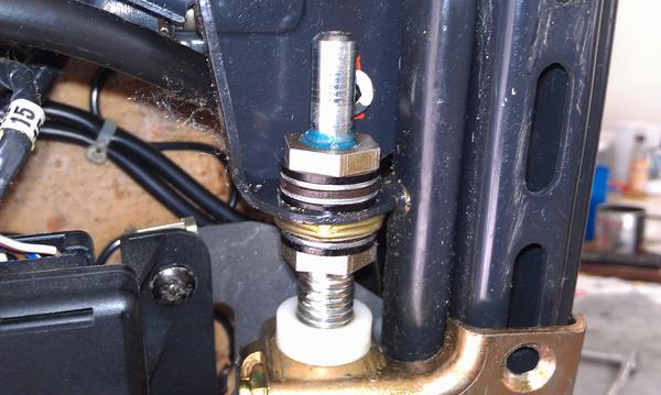
Drop a new nylon washer over the top end of the adjuster screw
followed by the other thrust bearing
and another nylon washer.
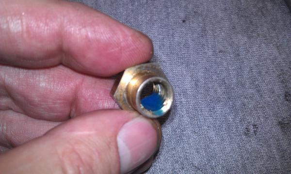
Apply the removable thread locking compound of your choice to the upper retaining nut
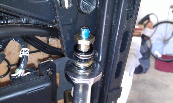
Slip the retaining nut onto the top end of the adjuster screw. Turn the adjuster screw to get the nut started.
As during removal, the nut will jam against the socket head screw for the front height adjuster at first so instead of trying to turn the upper retaining nut we screw the shaft into the nut using the lower retaining nut until the upper retaining nut is far enough on the adjusting screw shaft to clear the obstruction. You need to make sure that as you tighten down the upper retaining nut parts of the upper thrust bearing (nylon washer, bearing "races", cage and *****, and nylon washer) center on to the shoulder of the upper retaining nut.
Tighten the upper retaining nut securely.
Insert the drive cable, with locking pliers attached, into the end of the adjusting screw
Turn the drive cable and adjusting screw to bring the adjuster nut/bracket all the way up against the stop bushing.
Apply removable thread locking compound to both Phillips head screws and secure the adjuster bracket to the slider.
The following users liked this post:
Peter F (09-30-2022)
09-29-2013, 10:22 PM
#5
Rennlist Member
Thread Starter
Remove the locking pliers from the drive cable. Grasp the cable housing and install the motor end of the drive cable to the drive motor. Make sure the cable housing slips into the hole in the metal bracket.
Push the drive cable housing retaining clip back in to place to hold the cable housing. Be sure the housing isn't so far through the hole in the bracket so as to interfere with the manual seat drive gears.
Install the retaining clip on the adjusting screw end of the drive cable housing and that side is complete.
Repeat the entire process for the other side, making sure to re-install the wire retainer removed at the beginning, and the whole seat should be rock solid again. You may have to turn the drive cables slightly to get their square ends to align with the socket in the drive motor correctly but it won't be enough to affect straight travel or position.
Hope this helps
Mike
The following 2 users liked this post by ammonman:
Peter F (09-30-2022),
slate blue (07-06-2019)
 . Will come in handy in the near future.
Trending Topics
 08-31-2014, 05:24 PM
#11
Rennlist Member
Thread Starter
Sorry I don't have a source. They were never offered as spares by Porsche. You might be able to get them from Recaro, the original manufacturer of the seat.
Mike
Mike
05-17-2015, 10:39 AM
#14
Rennlist Member

I need a couple of these - anybody have some lying around?
 05-18-2015, 01:14 PM
#15
Drifting
Awesome write up --
My passenger seat in my 993 (same seats) is locked up and I tried to adjust the seat manually
with a drill on the speedo cable -- just ended up with shredded cable.
I can't find a bit to fit into the end of the adjustment mechanism to be able
to move the seats forward and back to be able to remove the seats.
I know its an S3 bit -- but no where can I find an S3 bit deep enough, and skinny
enough to get past the part where the cable clips in AND engage deep enough
to attempt to turn the mechanism.
So 2 Q's -- where can I find such a bit --
If it does not exist -- is there a way to move the seat fwd/backwards by some other means?
thx,
Mike