1984 FRONT WHEEL BEARINGS AND BRAKES PROCEDURE w/PICS
 01-29-2012, 08:24 PM
#1
Rennlist Member
Thread Starter
Join Date: Sep 2007
Location: Ridgecrest, California
Posts: 1,363
Likes: 0
Received 143 Likes
on
28 Posts
It's been too long since I've posted a procedure due to work schedule and other projects. Since I've just about got my work schedule back to reasonable, I decided to catch up on my backlog of procedures. Here's one for 1984 front bearings and brakes. As always, comments and suggestions for improvement are welcome! ENJOY!
1984 FRONT WHEEL BEARINGS AND BRAKES PROCEDURE
Version 1, January 2012
This step-by-step pictorial guide details the steps I followed to remove and replace the front wheel bearings and front brake rotors and pads on California (our 1984). The procedure does not include refurbishment of the brake calipers. There are rebuild kits available for the front and rear calipers for the 1984. I have written a procedure detailing the rebuild of the rear calipers titled, �1984 Rear Caliper Refurbish� but I do not have a detailed write up on the front calipers for the 1984. You may refer to the rear caliper rebuild procedure if you�re rebuilding the front calipers as the steps are similar.
The WSM recommends changing the brake fluid every 2 years with DOT 3 or equivalent fluid. This procedure does not cover bleeding or flushing the brake fluid as the fluid in the 1984 was still fresh from earlier work. However, if it is time to flush the brake fluid for your car, you may review another write up in Dwayne�s Garage titled, �1988 Brake Fluid Flush� and follow this procedure after the bearings and brakes have been done in this procedure.
WARNING: This is a Newbie-rated write up in that it provides a step-by-step pictorial guide and contains approximately 90 pictures. I intended to provide this level of detail so other Newbies like me could try this repair on their own, if desired. This write up pertains to an �84 MY 928.
CONTENTS: This write up covers:
PARTS-TOOLS-PREPARATION
REMOVING THE CALIPER
REMOVING THE ROTOR AND HUB
REMOVING THE BEARINGS AND RACES
INSTALLING THE RACES AND BEARINGS
INSTALLING THE HUB AND ROTOR
REMOVING THE BRAKE PADS
INSTALLING THE BRAKE PADS
INSTALLING THE CALIPER
PARTS-TOOLS-PREPARATION
BEARING PARTS: The front wheel bearings have inner bearings (located on the side of the hub facing the engine) and outer bearings (located on the side of the hub facing the wheel). The inner bearings are larger than the outer bearings and both are of a tapered roller bearing configuration. You will need 2 inner bearings and two outer bearings for the front wheel service. The bearings I�ve purchased through our 928 vendors also come with the appropriate bearing races. You will also need to purchase the inner bearing seal and you will need 2 of these to do both front wheels. Lastly, you will need wheel bearing grease to pack the new wheel bearings. I use high temperature disk brake wheel bearing grease (red) but other grease such as synthetic grease is also an option.
Inner Bearing part number: 999.059.090.00
Outer Bearing part number: 999.059.067.00
Inner Bearing Seal: 477.405.641
BRAKE PARTS: Typical wear components for a brake service are the brake pads and the brake rotor. This procedure does not cover brake hose/line or caliper refurbishment which entails additional parts. For the brake pads, they are sold in sets per wheel. You will need two sets. The inner pad and outer pad are different. The rotors are also different for left and right wheels and are slotted. Lastly, I like to use Disc Brake Quiet sprayed on the back side of the brake pads to help eliminate brake squeal/squeaks and I like to paint the rotor hat with caliper paint if they are not already painted (this is optional).
New brake pads are 13mm thick and the wear limit for brake pads is 2mm. New front rotors are 32mm thick and the wear limit is 30.6mm. If your pads and/or rotors are at or below the wear limits, they should be replaced.
Brake Pad part number (set for one wheel): 928.351.931.01
Brake Disc Rotor (Left): 928.351.043.01
Brake Disc Rotor (Right): 928.351.044.01
TOOLS: Standard tools I used for this job include:
Floor Jack
Jack stands
Porken�s Lift Bars (optional)
Metric combination wrench set and socket & ratchet set
Phillips and slotted screwdrivers
Channel Lock Pliers
Metric Allen Wrench (6mm)
Bearing and Race installation kit
Brass punch and hammer
Bearing Seal Puller
Non-Standard tools I used to remove the hub dust cap include:
Slide Hammer
Dust shield/cap removal tool (part number: 9165)
I used an oven and heat resistant gloves to ease the removal and installation of the bearing races in the hub.
PREPARATION: I recommend purchasing the needed parts and materials (grease, disc brake quiet, paint, etc.) before starting the work. When you receive your bearings and races, separate the bearing from the races and place all 4 bearings in a plastic baggie and place all 4 races in a separate plastic baggie. Put the bearing races in the freezer until you are ready to install them into the hub. This will ensure they are cold soaked for installation. At a minimum, I would recommend freezing them for a few hours.
 01-29-2012, 08:32 PM
#2
Rennlist Member
Thread Starter
Join Date: Sep 2007
Location: Ridgecrest, California
Posts: 1,363
Likes: 0
Received 143 Likes
on
28 Posts
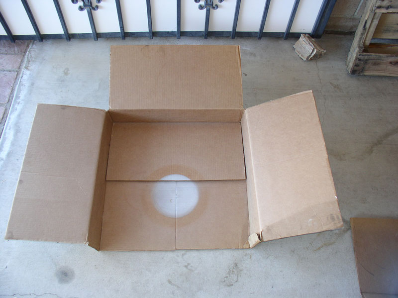
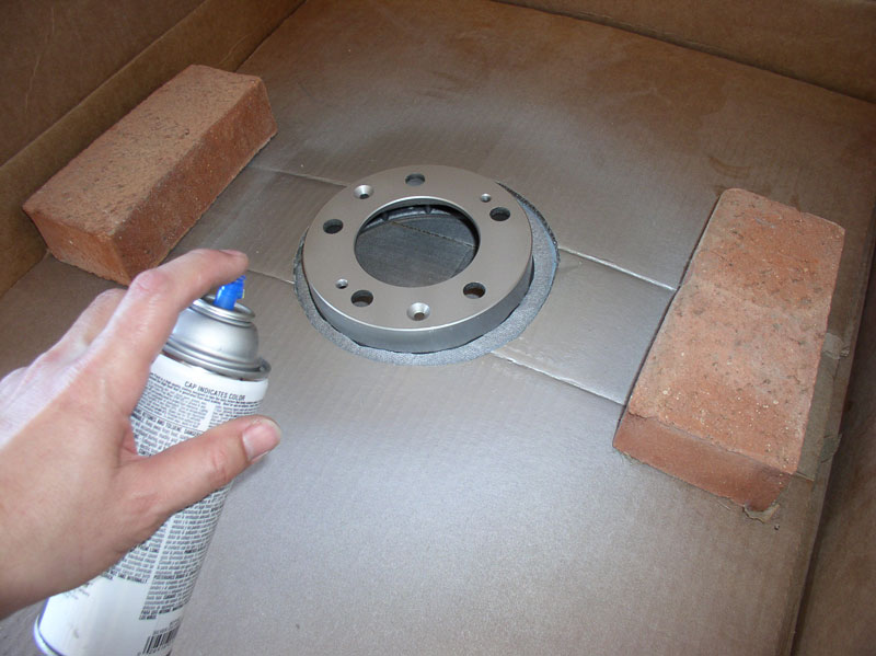
If you opt to paint the disc rotor hats, I recommend painting them before starting the work as the paint may need to dry overnight. Since I often paint rotor hats for the 928s, I wanted to fabricate something simple I could reuse and made painting the rotor hats fast and easy. I used a shallow cardboard box approximately 2 ft. square and a few inches high. I cut one side off the box as pictured below. I then save the cardboard box for future rotor painting.
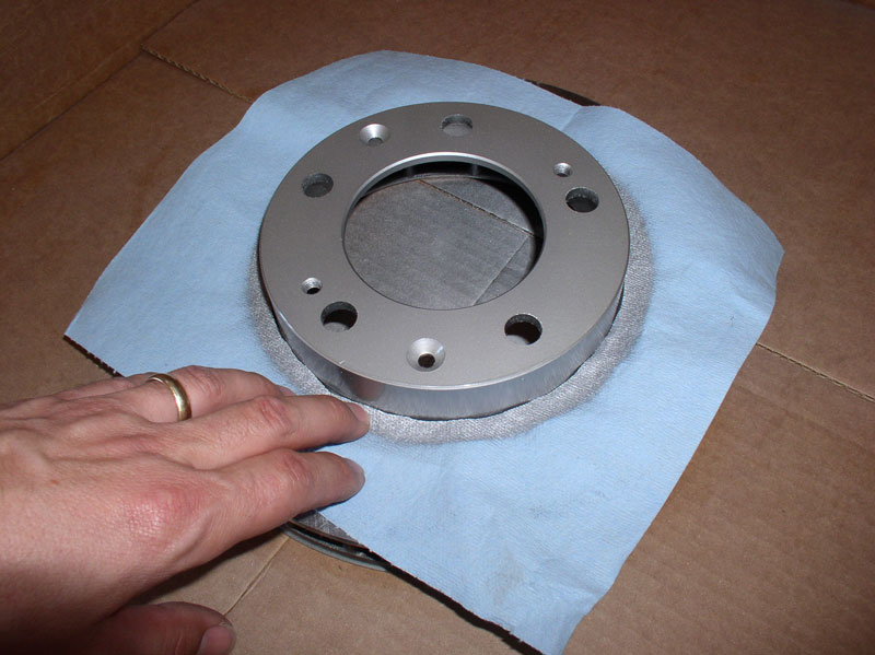
I trace the outline diameter of the hat on a thick paper towel (or a piece of thin cardboard would also work) and cut out the center of the paper towel. Then place the paper towel over the rotor hat as shown below. This will prevent paint from getting on the rotor surface. The paper towel can also be saved and used for future paint jobs.
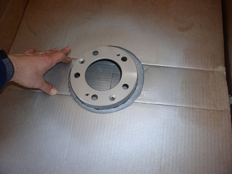
I then trace a slightly larger outline of the rotor hat diameter on a large piece of cardboard and cut out the center and place the large cardboard centered over the rotor hat as pictured below. This will keep the paper towel from moving around when spray painting. I also save the cardboard template for future rotor had paint jobs.
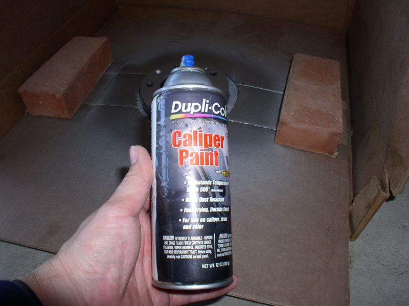
If the cardboard won�t lay flat, use a couple of weights such as bricks, rocks or wood scraps to hold it down as shown below. I use Dupli-Color Caliper Paint in the silver color and have had excellent results. Begin spraying light, even coats over the rotor hat. I usually apply 3 coats keeping them light and avoiding runs.
After the paint coats have dried, I usually apply 3 coats of High Temperature clear coat over the rotor just painted. I let the paint harden over night and then install on the wheel when ready.
REMOVING THE CALIPER
First, loosen the wheel lug nuts with a 19mm socket while the car is on the ground. If you are using an impact wrench, this step may not be necessary.
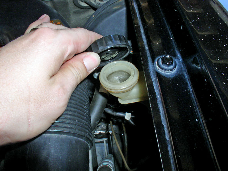
Under the hood, loosen the cap on the brake fluid reservoir. This will allow brake fluid to be �pushed� back into the reservoir when removing the old brake pads. As an extra precaution, it�s a good idea to place a towel/rag down around the brake filler neck to catch and absorb any brake fluid that may overflow.
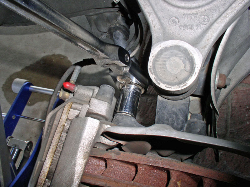
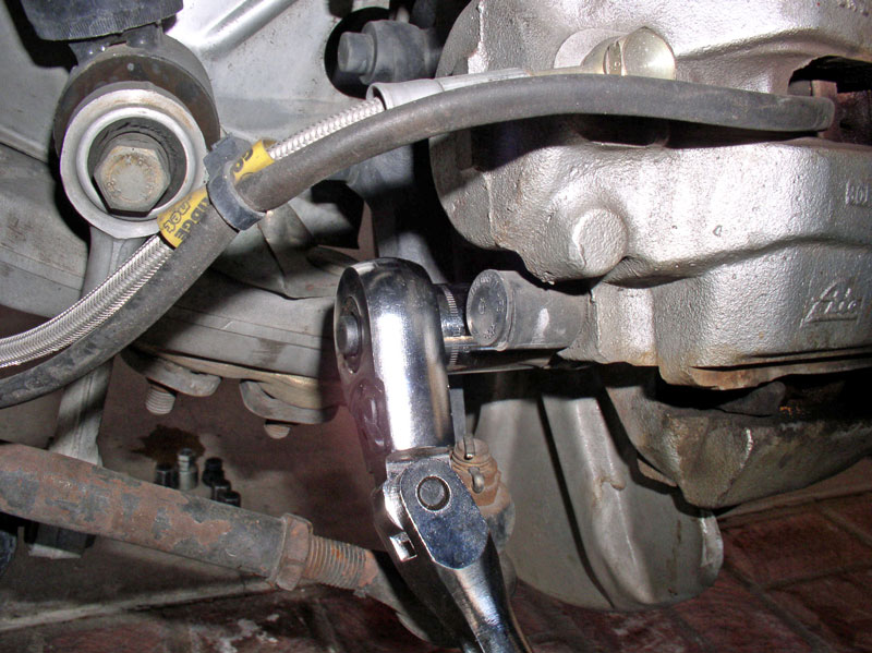
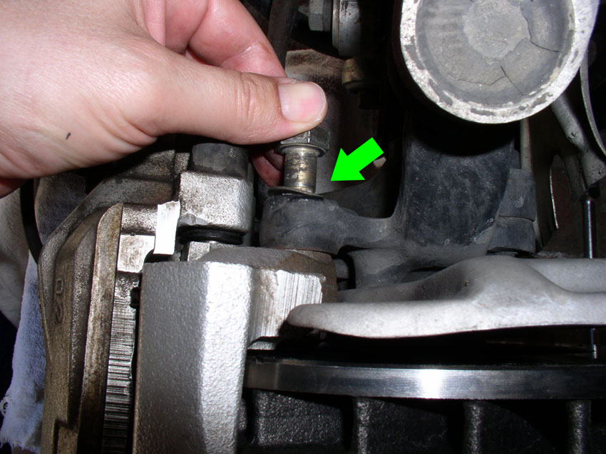
Next, lift the front end of the car or place the car on lift bars or a lift and remove the front wheels. Using a 19mm socket or wrench, loosen and remove the caliper bolts. The location of the upper bolt is shown below. I have found using a long handled �� drive ratchet with articulating head works great for this application since the bolts can be hard to remove.
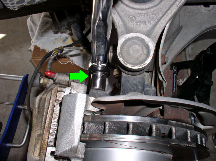
Remove the lower caliper bolt as depicted below.
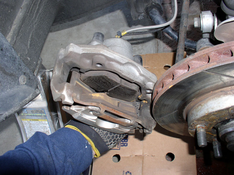
At this point, the caliper will be loose and can be removed from the rotor. However, if the rotor is worn significantly, there will probably be a �lip� at the outer edge of the rotor that will prevent you from simply sliding the caliper and brake pads off the rotor. If the caliper does not slide off easily and you can feel the lip at the outer edge of the rotor, you will need to compress the caliper piston in order to create enough clearance to remove the caliper. To do this, I use a large �C� clamp (6� or 8�) placed on the caliper piston housing and the other end of the clamp on the outer surface of the rotor and tighten down just enough to clear the rotor. When tightening the �C� clamp, this forces brake fluid back into the reservoir so keep an eye on the fluid level to make sure no fluid spills out. Once there is clearance, slide the caliper off the rotor.
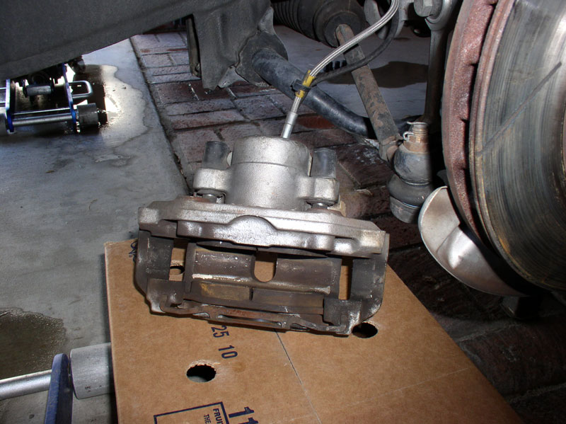
Set the rotor aside by either resting on a box or hanging/suspended by a wire being careful not to place stress on the brake fluid line.
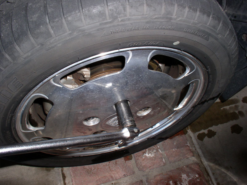
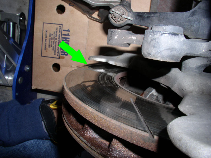
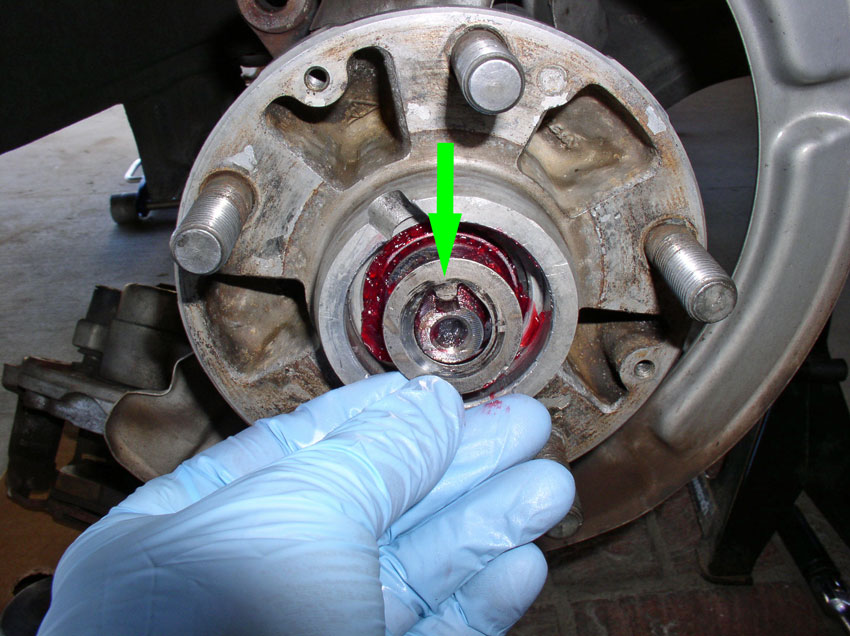
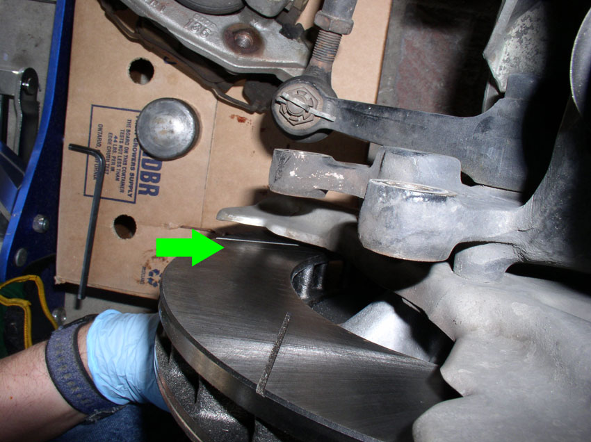
Before removing the rotor, I like to check for any rotor warp or misalignment. On the 1984, I had been experiencing brake pedal pulsing at low speeds and front end vibration at high speeds when applying the brake. There is a tool designed to check for rotor warp-alignment-runout but I didn�t have one at the time so here�s a quick and dirty tip to check for rotor true-ness. Looking at the backside of the rotor, pick out a stationary object reflected in the rotor surface. In the picture below, I used the reflection of the dust shield as depicted by the green arrow. Next, spin the rotor with one hand while watching what the reflection does on the rotor surface. If the rotor is true, the reflection of the dust shield will remain motionless while the rotor is spinning. If you see the reflection moving, as I observed on my test, the rotor is most likely warped or not seated properly on the hub.
REMOVING THE ROTOR AND HUB
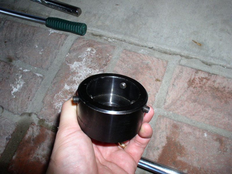
In order to remove the hub, you will need to remove the hub dust shield. Various techniques and workaround tools can be used to remove the hub. After using some of these, I decided to purchase the recommended tool to remove the dust shield and I must say, I�m glad I did because it made the job much easier. Here�s a pic of the special tool (part number 9165) used.
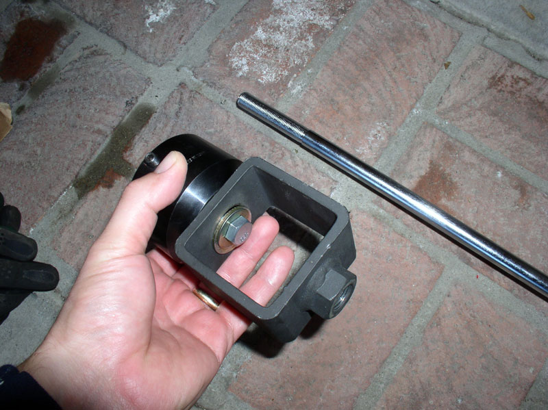
The special tool works with a slide hammer. Here�s the slide hammer adaptor attached to the dust shield removal tool.
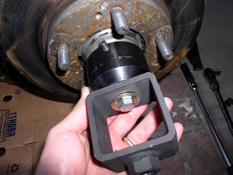
The dust shield removal tool fits over the dust shield and 3 Allen set screws (4mm) are tightened down to secure the tool to the dust shield.
Continued....
I trace the outline diameter of the hat on a thick paper towel (or a piece of thin cardboard would also work) and cut out the center of the paper towel. Then place the paper towel over the rotor hat as shown below. This will prevent paint from getting on the rotor surface. The paper towel can also be saved and used for future paint jobs.
I then trace a slightly larger outline of the rotor hat diameter on a large piece of cardboard and cut out the center and place the large cardboard centered over the rotor hat as pictured below. This will keep the paper towel from moving around when spray painting. I also save the cardboard template for future rotor had paint jobs.
If the cardboard won�t lay flat, use a couple of weights such as bricks, rocks or wood scraps to hold it down as shown below. I use Dupli-Color Caliper Paint in the silver color and have had excellent results. Begin spraying light, even coats over the rotor hat. I usually apply 3 coats keeping them light and avoiding runs.
After the paint coats have dried, I usually apply 3 coats of High Temperature clear coat over the rotor just painted. I let the paint harden over night and then install on the wheel when ready.
REMOVING THE CALIPER
First, loosen the wheel lug nuts with a 19mm socket while the car is on the ground. If you are using an impact wrench, this step may not be necessary.
Under the hood, loosen the cap on the brake fluid reservoir. This will allow brake fluid to be �pushed� back into the reservoir when removing the old brake pads. As an extra precaution, it�s a good idea to place a towel/rag down around the brake filler neck to catch and absorb any brake fluid that may overflow.
Next, lift the front end of the car or place the car on lift bars or a lift and remove the front wheels. Using a 19mm socket or wrench, loosen and remove the caliper bolts. The location of the upper bolt is shown below. I have found using a long handled �� drive ratchet with articulating head works great for this application since the bolts can be hard to remove.
Remove the lower caliper bolt as depicted below.
At this point, the caliper will be loose and can be removed from the rotor. However, if the rotor is worn significantly, there will probably be a �lip� at the outer edge of the rotor that will prevent you from simply sliding the caliper and brake pads off the rotor. If the caliper does not slide off easily and you can feel the lip at the outer edge of the rotor, you will need to compress the caliper piston in order to create enough clearance to remove the caliper. To do this, I use a large �C� clamp (6� or 8�) placed on the caliper piston housing and the other end of the clamp on the outer surface of the rotor and tighten down just enough to clear the rotor. When tightening the �C� clamp, this forces brake fluid back into the reservoir so keep an eye on the fluid level to make sure no fluid spills out. Once there is clearance, slide the caliper off the rotor.
Set the rotor aside by either resting on a box or hanging/suspended by a wire being careful not to place stress on the brake fluid line.
Before removing the rotor, I like to check for any rotor warp or misalignment. On the 1984, I had been experiencing brake pedal pulsing at low speeds and front end vibration at high speeds when applying the brake. There is a tool designed to check for rotor warp-alignment-runout but I didn�t have one at the time so here�s a quick and dirty tip to check for rotor true-ness. Looking at the backside of the rotor, pick out a stationary object reflected in the rotor surface. In the picture below, I used the reflection of the dust shield as depicted by the green arrow. Next, spin the rotor with one hand while watching what the reflection does on the rotor surface. If the rotor is true, the reflection of the dust shield will remain motionless while the rotor is spinning. If you see the reflection moving, as I observed on my test, the rotor is most likely warped or not seated properly on the hub.
REMOVING THE ROTOR AND HUB
In order to remove the hub, you will need to remove the hub dust shield. Various techniques and workaround tools can be used to remove the hub. After using some of these, I decided to purchase the recommended tool to remove the dust shield and I must say, I�m glad I did because it made the job much easier. Here�s a pic of the special tool (part number 9165) used.
The special tool works with a slide hammer. Here�s the slide hammer adaptor attached to the dust shield removal tool.
The dust shield removal tool fits over the dust shield and 3 Allen set screws (4mm) are tightened down to secure the tool to the dust shield.
Continued....
01-29-2012, 08:39 PM
#3
Rennlist Member
Thread Starter
Join Date: Sep 2007
Location: Ridgecrest, California
Posts: 1,363
Likes: 0
Received 143 Likes
on
28 Posts
Next, attach the slide hammer. I applied 3 moderate “tugs”….
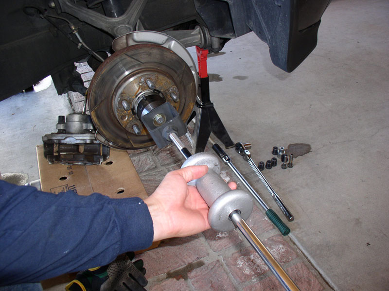
…and the dust shield comes off without a hitch!
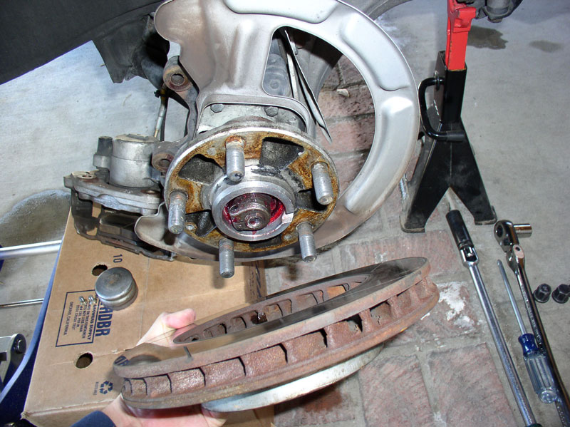
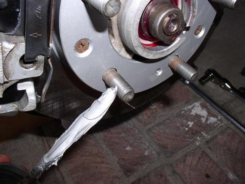
The rotor is secured to the hub with 2 Phillips head screws. Use a large Phillips screwdriver to remove the two screws. These screws are only supposed to be torqued to about 7 ftlbs but sometimes they are stubborn to come out. In this case, I use a manual (using a hammer) impact driver with Phillips tip. Once the screws are out, you should be able to remove the rotor from the hub. If the rotor is stuck, you may use an M8 bolt to “force” the rotor off. Insert the bolt into one of the two threaded holes in the rotor designed for this purpose. You can see the holes just to the left of the stud at the 11 o’clock position and the stud at the 4 o’clock position in the picture below. Use a 13mm wrench or socket to tighten the bolt and the rotor will easily break free.
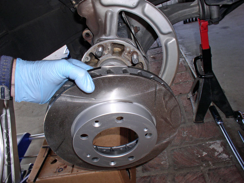
Remove the rotor.
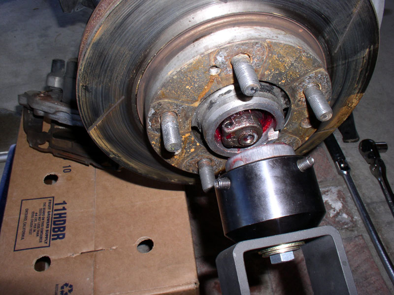
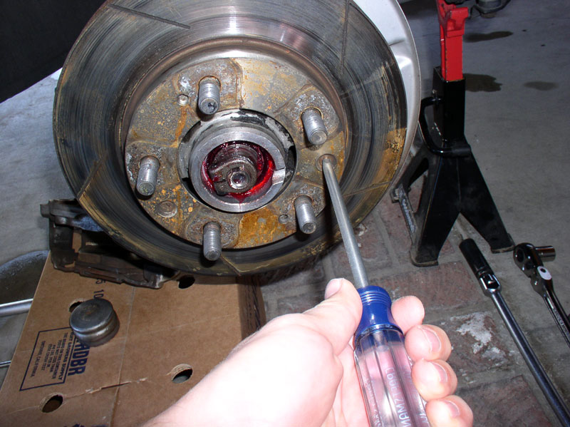
According to the WSM, the wheel bearing thrust washer located just behind the spindle nut should just barely move about when applying a screwdriver and human strength only – in other words, without levering the screwdriver against the hub. If the thrust washer can not be moved about using unassisted human strength, then the spindle clamp nut is considered too tight and may cause premature bearing failure or spindle/hub damage.
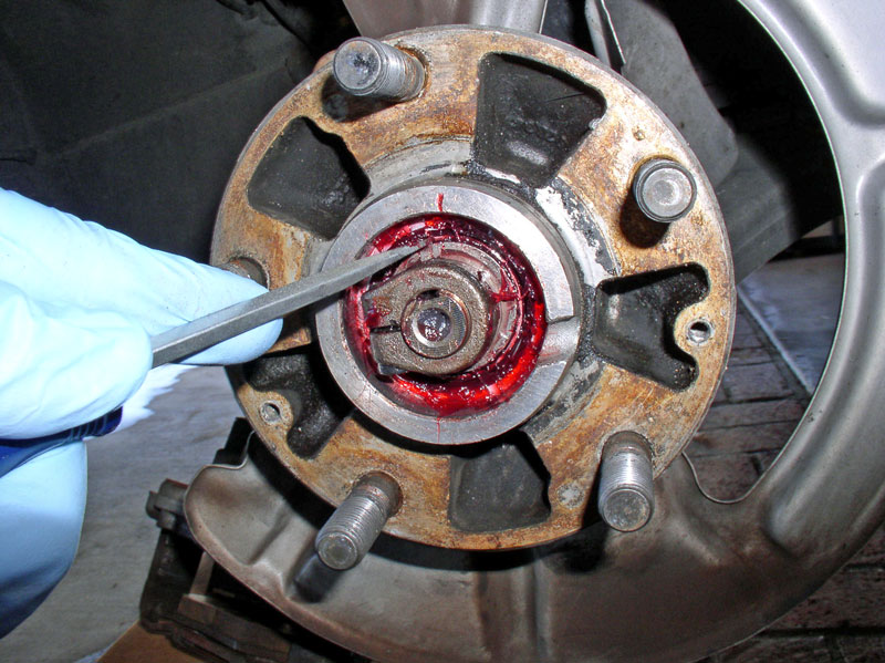
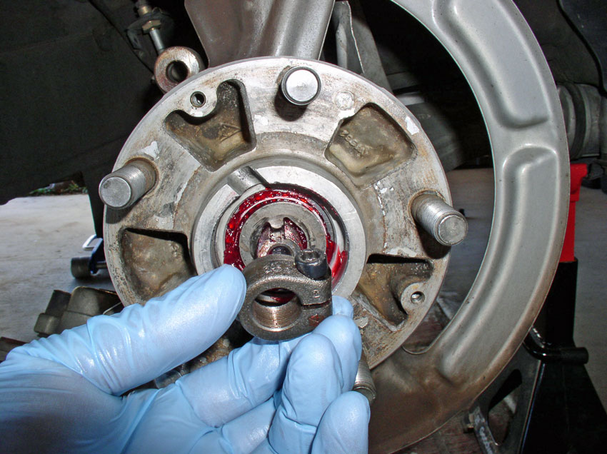
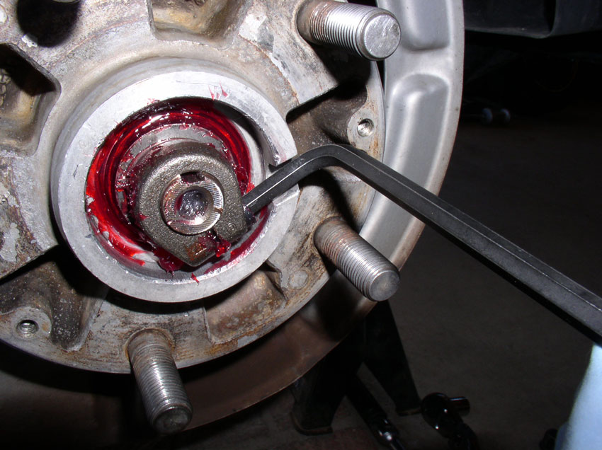
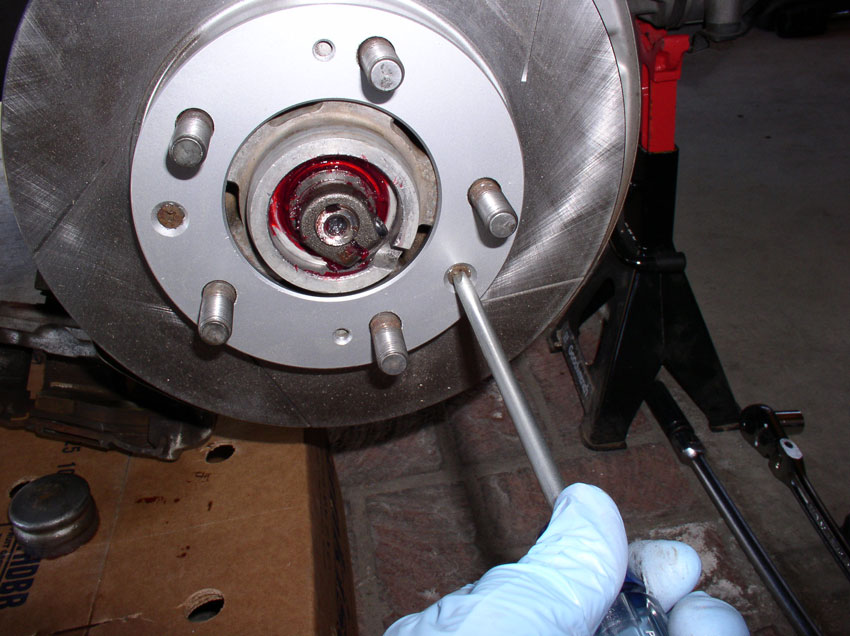
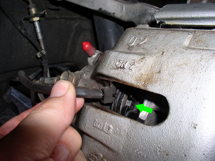
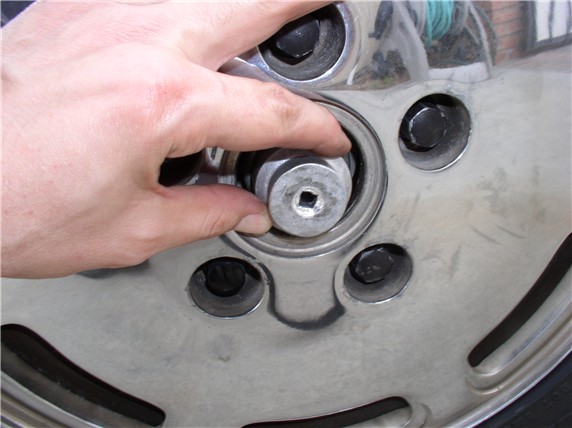
After checking the thrust washer free play just for fun, remove the spindle nut. The spindle nut is a locking clamp designed to provide ability to properly adjust thrust washer/bearing pressure. It takes a 6mm Allen wrench to loosen the clamp in order to remove it. The Allen bolt can only be accessed by rotating the hub so the access slot cut into the hub lines up with the Allen bolt as pictured below. Ensure the Allen wrench is fully seated in the bolt and loosen the bolt.
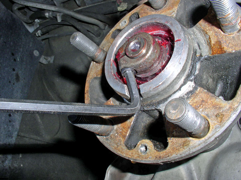
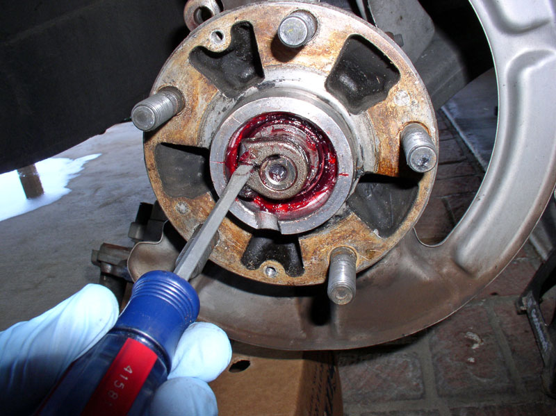
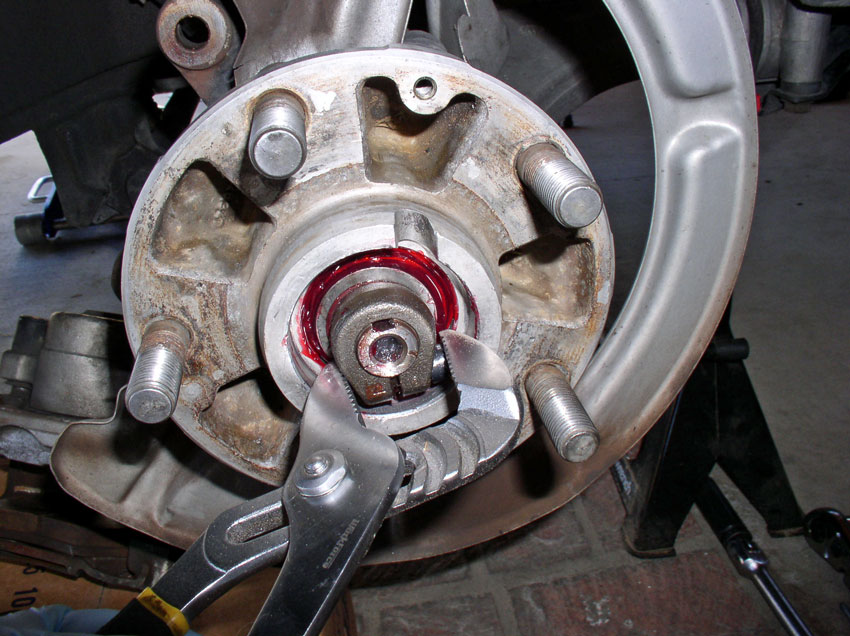
If the clamp nut does not come off easily after loosening the Allen bolt, you may try prying the clamp apart slightly with a flat blade screwdriver. If you’re still having trouble getting the clamp bolt off, you can use a pair of channel lock pliers to get a grip on the clamp nut and twist it off.
Remove the clamp nut.
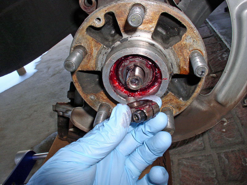
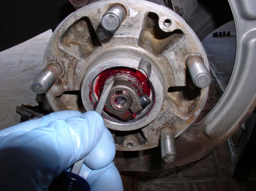
Remove the bearing thrust washer. Note the notch cut into the thrust washer matches up with the slot cut into the spindle.
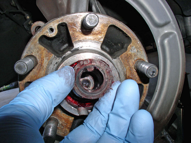
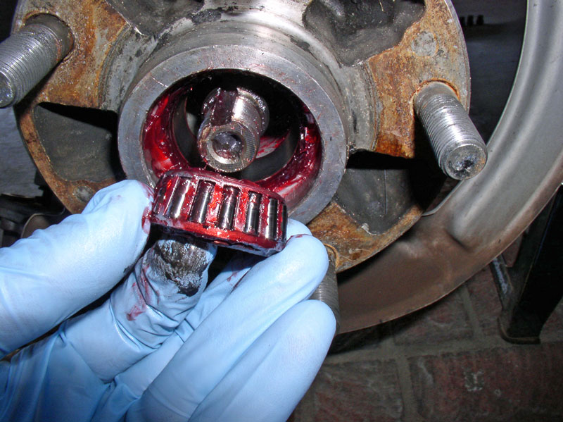
The outer wheel bearings should come out easily now. I removed them next.
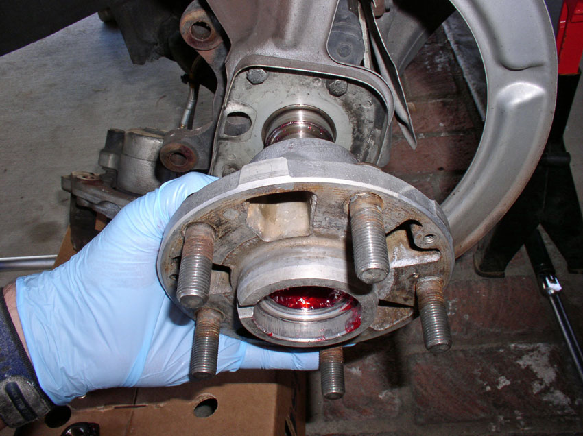
Finally, the hub can be removed from the hub by pulling it outward from the car. A gentle rocking and twisting motion while pulling will help it come off easily.
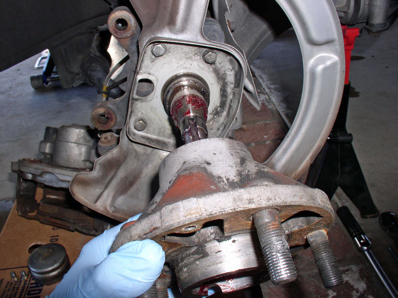
Once the hub is off, clean off the spindle for inspection.
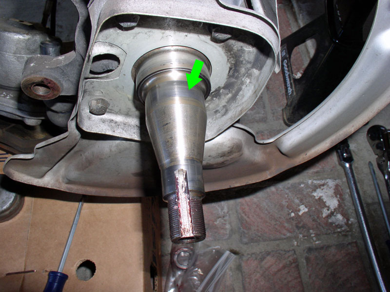
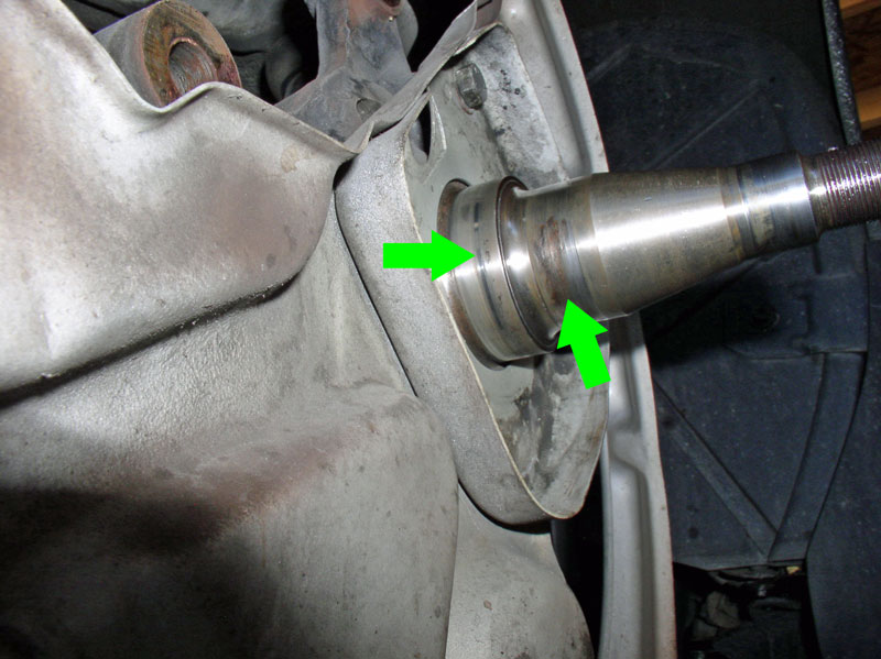
When inspecting the spindle, you may notice wear patterns. Depicted in the picture below, you can see where the inner bearing rests on the spindle as shown by the green arrow.
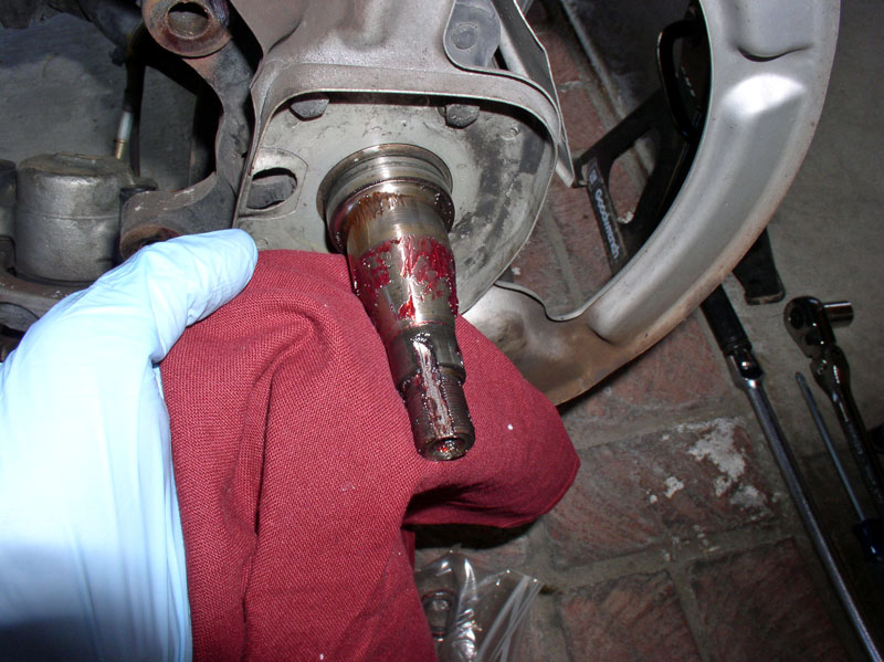
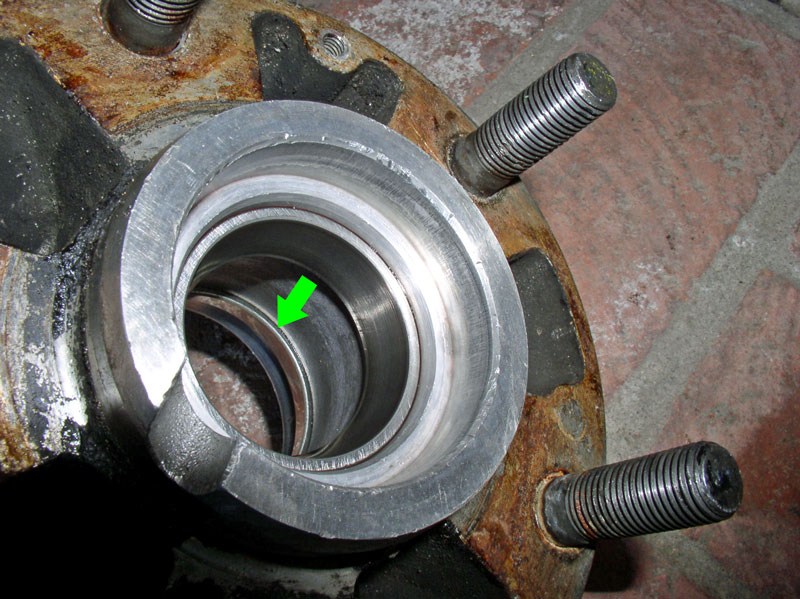
Looking at the underside of the spindle, you can see wear spots for the inner bearing (right green arrow) and the inner bearing seal (left green arrow). Since the seal is rubber and no metal part of the seal is intended to come into contact with the spindle, the marking on the spindle below is most likely “polishing” affect from the rubber seal. I don’t know if there are established wear limits for the spindle but you can run your finger tips over the bearing seat area to feel for spindle wear. If you detect anything more than barely perceptible wear, it may be a good idea to look into replacing the spindle. Another method of checking for wear is to use a micrometer and check spindle thickness at various locations around the spindle where the inner bearing seat is located.
REMOVING THE BEARINGS AND RACES
Now that the hub is removed, you can take a closer look at the hub assembly. At the inside end of the hub, you will notice the inner bearing seal depicted by the upper green arrow. It is a pressed fit and the rubber seal on the inside prevents grease from escaping the hub enclosure and prevents dust and debris from entering. The inner bearing is also visible and depicted by the lower green arrow below. You can not remove the inner bearing without first removing the bearing seal.
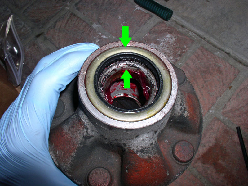
Continued...
…and the dust shield comes off without a hitch!
The rotor is secured to the hub with 2 Phillips head screws. Use a large Phillips screwdriver to remove the two screws. These screws are only supposed to be torqued to about 7 ftlbs but sometimes they are stubborn to come out. In this case, I use a manual (using a hammer) impact driver with Phillips tip. Once the screws are out, you should be able to remove the rotor from the hub. If the rotor is stuck, you may use an M8 bolt to “force” the rotor off. Insert the bolt into one of the two threaded holes in the rotor designed for this purpose. You can see the holes just to the left of the stud at the 11 o’clock position and the stud at the 4 o’clock position in the picture below. Use a 13mm wrench or socket to tighten the bolt and the rotor will easily break free.
Remove the rotor.
According to the WSM, the wheel bearing thrust washer located just behind the spindle nut should just barely move about when applying a screwdriver and human strength only – in other words, without levering the screwdriver against the hub. If the thrust washer can not be moved about using unassisted human strength, then the spindle clamp nut is considered too tight and may cause premature bearing failure or spindle/hub damage.
After checking the thrust washer free play just for fun, remove the spindle nut. The spindle nut is a locking clamp designed to provide ability to properly adjust thrust washer/bearing pressure. It takes a 6mm Allen wrench to loosen the clamp in order to remove it. The Allen bolt can only be accessed by rotating the hub so the access slot cut into the hub lines up with the Allen bolt as pictured below. Ensure the Allen wrench is fully seated in the bolt and loosen the bolt.
If the clamp nut does not come off easily after loosening the Allen bolt, you may try prying the clamp apart slightly with a flat blade screwdriver. If you’re still having trouble getting the clamp bolt off, you can use a pair of channel lock pliers to get a grip on the clamp nut and twist it off.
Remove the clamp nut.
Remove the bearing thrust washer. Note the notch cut into the thrust washer matches up with the slot cut into the spindle.
The outer wheel bearings should come out easily now. I removed them next.
Finally, the hub can be removed from the hub by pulling it outward from the car. A gentle rocking and twisting motion while pulling will help it come off easily.
Once the hub is off, clean off the spindle for inspection.
When inspecting the spindle, you may notice wear patterns. Depicted in the picture below, you can see where the inner bearing rests on the spindle as shown by the green arrow.
Looking at the underside of the spindle, you can see wear spots for the inner bearing (right green arrow) and the inner bearing seal (left green arrow). Since the seal is rubber and no metal part of the seal is intended to come into contact with the spindle, the marking on the spindle below is most likely “polishing” affect from the rubber seal. I don’t know if there are established wear limits for the spindle but you can run your finger tips over the bearing seat area to feel for spindle wear. If you detect anything more than barely perceptible wear, it may be a good idea to look into replacing the spindle. Another method of checking for wear is to use a micrometer and check spindle thickness at various locations around the spindle where the inner bearing seat is located.
REMOVING THE BEARINGS AND RACES
Now that the hub is removed, you can take a closer look at the hub assembly. At the inside end of the hub, you will notice the inner bearing seal depicted by the upper green arrow. It is a pressed fit and the rubber seal on the inside prevents grease from escaping the hub enclosure and prevents dust and debris from entering. The inner bearing is also visible and depicted by the lower green arrow below. You can not remove the inner bearing without first removing the bearing seal.
Continued...
01-29-2012, 08:46 PM
#4
Rennlist Member
Thread Starter
Join Date: Sep 2007
Location: Ridgecrest, California
Posts: 1,363
Likes: 0
Received 143 Likes
on
28 Posts
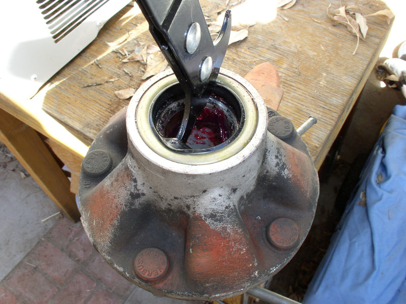
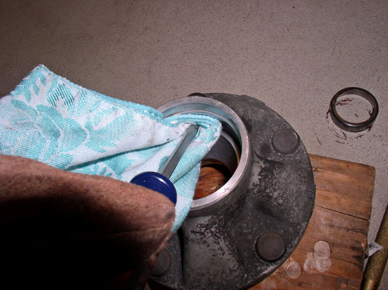
To remove the inner bearing seal, secure the hub in a vice or sturdy clamp. Use a bearing seal puller to pry the seal out from the hub being careful not to scratch or damage the inside of the hub or the outer surface of the hub.
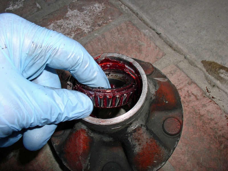
Once the seal is removed, the inner bearings can be easily removed. Note the orientation of the bearings as pictured below.
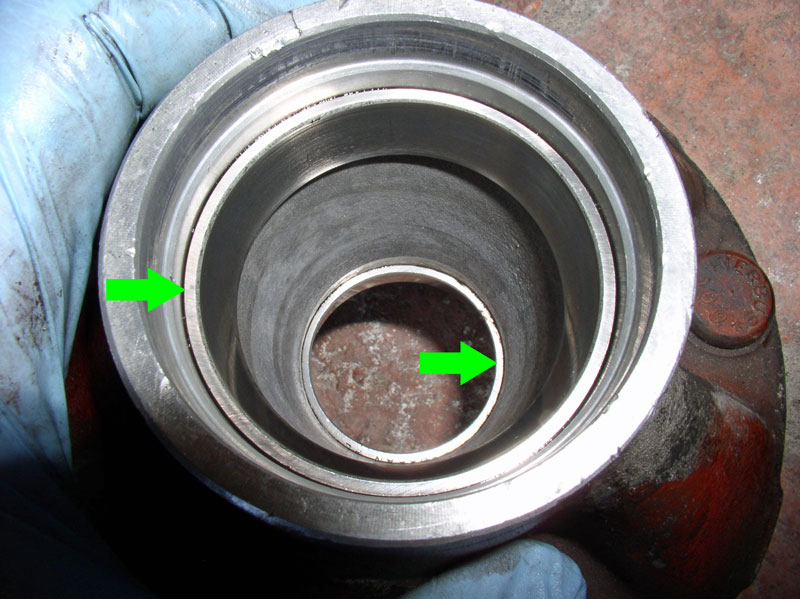
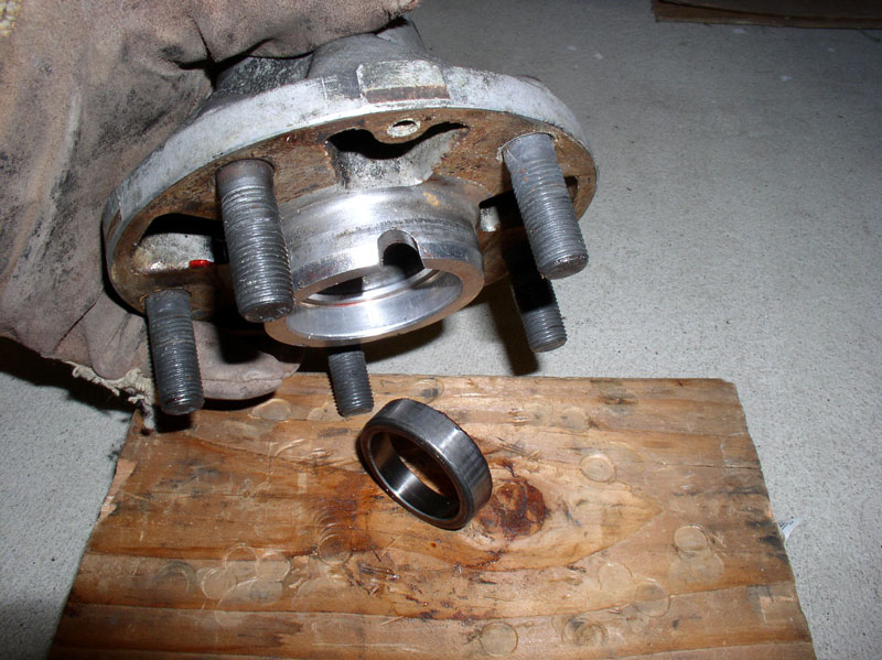
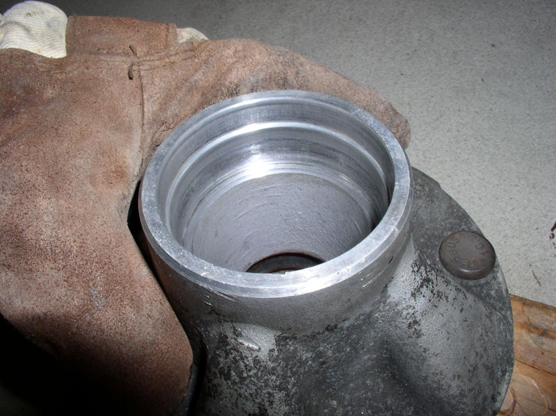
After the bearings have been removed, wipe down and clean the inside and outside of the hub. The inner and outer roller bearings rest on the inner and outer races that are pressed into the hub housing. The inner, larger, race is identified by the left green arrow and the outer bearing race is depicted by the right green arrow in the picture below. Please note the taper on the races. When removing the races, the new races must be installed in the same orientation. You will notice from the picture below, the outer race (right green arrow) has a ‘lip’ protruding from its seat in the hub. This will be used to remove the race later on.
Looking at the underside of the inner race, you will notice it also has a ‘lip’ protruding from the hub seat as shown by the green arrow below. This ‘lip’ will also be used to remove the race.
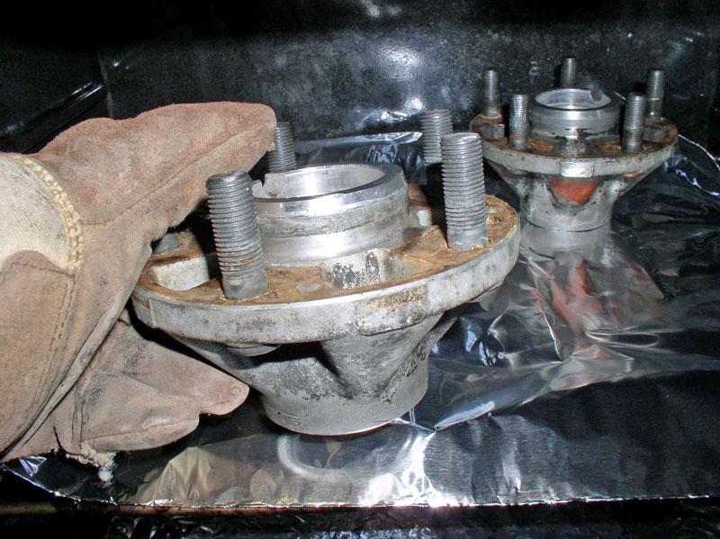
Although the bearing races can be removed from the hub cold, the WSM recommends heating the hub to between 250-300 degrees F. I have tried removing races both hot and cold and I have to say, HOT is the way to go. The races fall out with light tapping when the hub is heated. If you are going to use your home oven for this job, make sure your hubs are squeaky clean as they will create a smell when heated (also might want to make sure the spouse is not home when you do this). Now is a great time to wire brush around the studs and at the base of each stud as well as wire brush the mating surface of the wheel side of the hub. It is important that these areas be clean before installing the new rotors on the hub as debris and rust can get under the rotor and hub mating surface and cause the rotor to not run straight and true. Admittedly, the hubs pictured below are not clean enough for final installation and I ended up giving them a good scrub again before installation. I placed aluminum foil on the oven rack and heated the hubs to 300 degrees F. I left them in the oven for about 30 minutes so they would get heat soaked. Use a pair of heat resistant gloves to remove and work with the hub when done baking.
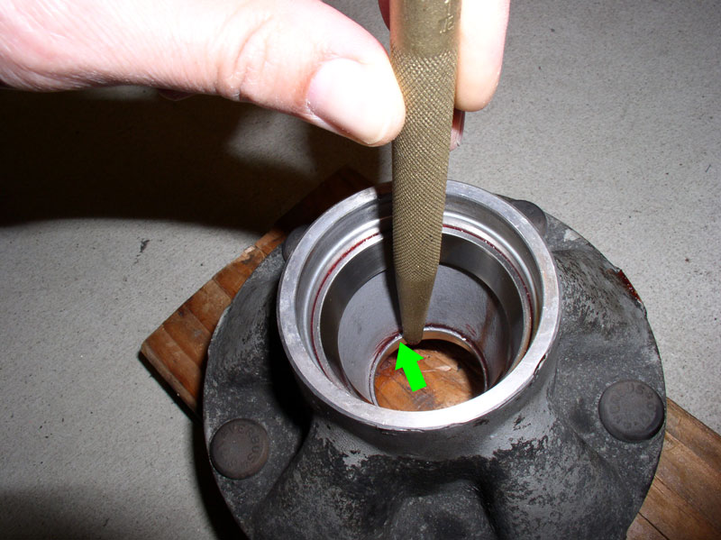
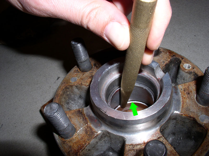
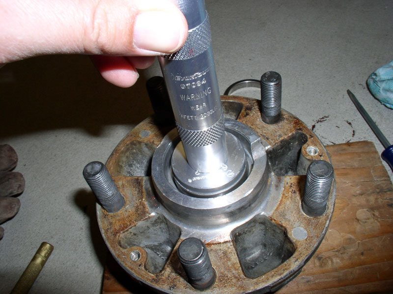
Move quickly to remove the races while the hub is hot. I placed the hub on a scrap piece of lumber and used a brass punch resting on the edge of the ‘lip’ to tap the race out of the hub seat. See picture below.
I was surprised at how easily the race came out compared to trying to remove the race when the hub is cold.
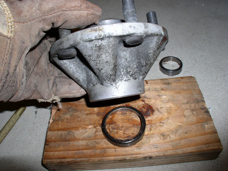
Flip the hub over and repeat the process for the other race being careful to place the brass punch on the ‘lip’ as pictured below.
…and the second race comes out easy as falling off a log!
Once the races are out, clean out the seats in the hub to prepare for installing the new races.
Here’s a picture of the inner side of the hub where you can see the seat for the inner bearing race and the seat for the inner bearing seal.
INSTALLING THE RACES AND BEARINGS
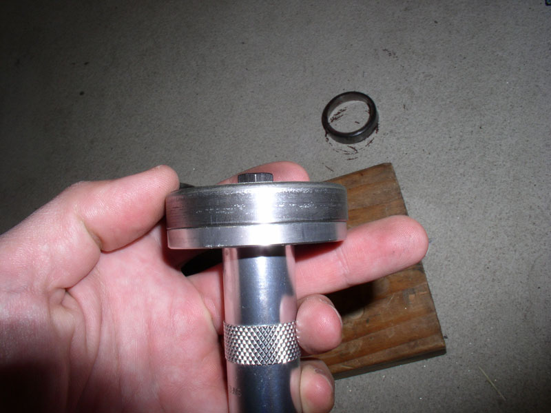
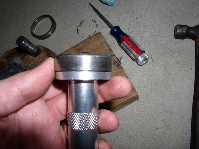
If you are moving quickly enough, you may be able to install the races while the hub is still hot and expanded. If not, you can always re-heat the hubs for installing the races which is highly recommended to get a good, flush, fully seated install of the bearing races. Before installing the races, identify the correct size race installer for each of the races by matching them up to the old races that came out of the hub.
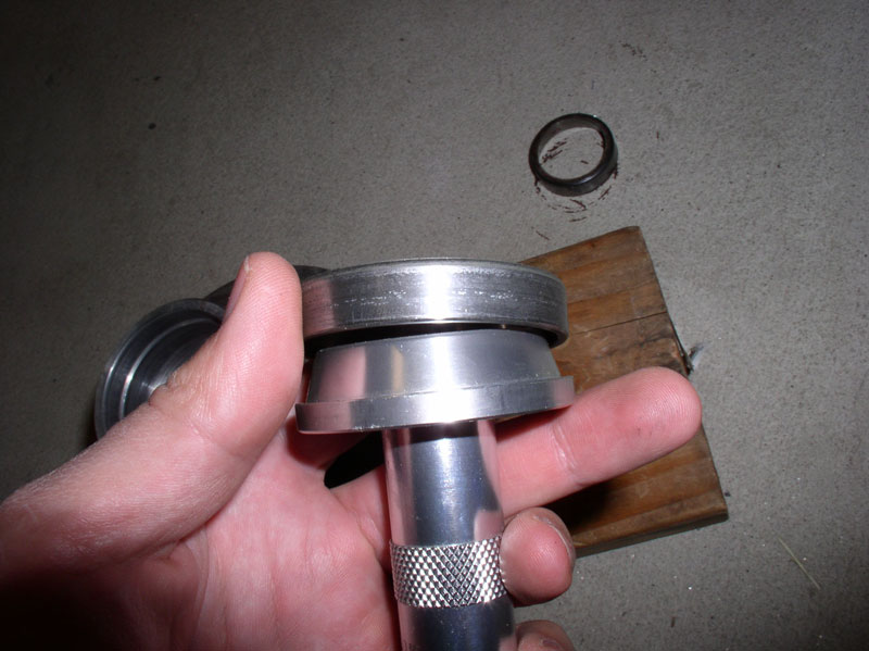
The installer should be slightly smaller than the diameter of the race as pictured below in order to avoid possibly damaging the race seat in the hub.
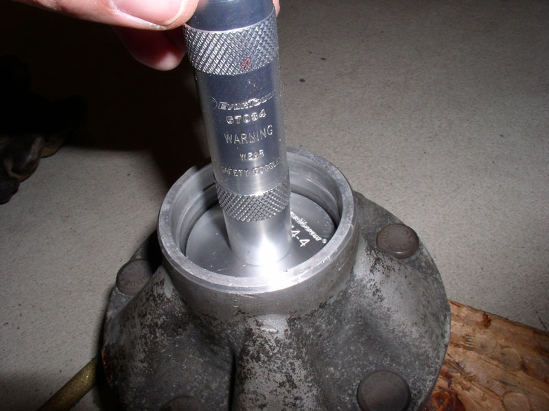
Now that you have the race installer configured with both dies ready, it’s time to get your hot hubs and frozen races. I started with the larger, inner race installation. However, it is advisable to start with the smaller, inner race. Reason being the larger, outer race may have a tendency to be dislodged (or fall out) when you are installing/tapping the smaller, inner race into place while the hub is still hot. This tip was provided by Mrmerlin from personal experience - THANKS for the tip, Stan! Place the hub on a scrap of wood and carefully drop the frozen race into its seat ensuring the tapered side is facing up. Then apply the installer with a few taps with the hammer to fully seat the race. You will notice a change in the pitch of the hammer blows as the race fully seats in the hub. Move on to the other hub and install the inner race while hot.
Next, I changed the race installer die to fit the smaller outer race.
Continued...
Once the seal is removed, the inner bearings can be easily removed. Note the orientation of the bearings as pictured below.
After the bearings have been removed, wipe down and clean the inside and outside of the hub. The inner and outer roller bearings rest on the inner and outer races that are pressed into the hub housing. The inner, larger, race is identified by the left green arrow and the outer bearing race is depicted by the right green arrow in the picture below. Please note the taper on the races. When removing the races, the new races must be installed in the same orientation. You will notice from the picture below, the outer race (right green arrow) has a ‘lip’ protruding from its seat in the hub. This will be used to remove the race later on.
Looking at the underside of the inner race, you will notice it also has a ‘lip’ protruding from the hub seat as shown by the green arrow below. This ‘lip’ will also be used to remove the race.
Although the bearing races can be removed from the hub cold, the WSM recommends heating the hub to between 250-300 degrees F. I have tried removing races both hot and cold and I have to say, HOT is the way to go. The races fall out with light tapping when the hub is heated. If you are going to use your home oven for this job, make sure your hubs are squeaky clean as they will create a smell when heated (also might want to make sure the spouse is not home when you do this). Now is a great time to wire brush around the studs and at the base of each stud as well as wire brush the mating surface of the wheel side of the hub. It is important that these areas be clean before installing the new rotors on the hub as debris and rust can get under the rotor and hub mating surface and cause the rotor to not run straight and true. Admittedly, the hubs pictured below are not clean enough for final installation and I ended up giving them a good scrub again before installation. I placed aluminum foil on the oven rack and heated the hubs to 300 degrees F. I left them in the oven for about 30 minutes so they would get heat soaked. Use a pair of heat resistant gloves to remove and work with the hub when done baking.
Move quickly to remove the races while the hub is hot. I placed the hub on a scrap piece of lumber and used a brass punch resting on the edge of the ‘lip’ to tap the race out of the hub seat. See picture below.
I was surprised at how easily the race came out compared to trying to remove the race when the hub is cold.
Flip the hub over and repeat the process for the other race being careful to place the brass punch on the ‘lip’ as pictured below.
…and the second race comes out easy as falling off a log!
Once the races are out, clean out the seats in the hub to prepare for installing the new races.
Here’s a picture of the inner side of the hub where you can see the seat for the inner bearing race and the seat for the inner bearing seal.
INSTALLING THE RACES AND BEARINGS
If you are moving quickly enough, you may be able to install the races while the hub is still hot and expanded. If not, you can always re-heat the hubs for installing the races which is highly recommended to get a good, flush, fully seated install of the bearing races. Before installing the races, identify the correct size race installer for each of the races by matching them up to the old races that came out of the hub.
The installer should be slightly smaller than the diameter of the race as pictured below in order to avoid possibly damaging the race seat in the hub.
Now that you have the race installer configured with both dies ready, it’s time to get your hot hubs and frozen races. I started with the larger, inner race installation. However, it is advisable to start with the smaller, inner race. Reason being the larger, outer race may have a tendency to be dislodged (or fall out) when you are installing/tapping the smaller, inner race into place while the hub is still hot. This tip was provided by Mrmerlin from personal experience - THANKS for the tip, Stan! Place the hub on a scrap of wood and carefully drop the frozen race into its seat ensuring the tapered side is facing up. Then apply the installer with a few taps with the hammer to fully seat the race. You will notice a change in the pitch of the hammer blows as the race fully seats in the hub. Move on to the other hub and install the inner race while hot.
Next, I changed the race installer die to fit the smaller outer race.
Continued...
01-29-2012, 08:53 PM
#5
Rennlist Member
Thread Starter
Join Date: Sep 2007
Location: Ridgecrest, California
Posts: 1,363
Likes: 0
Received 143 Likes
on
28 Posts
Drop the inner race into place and apply the installer as with the larger inner race. Tap it into place until fully seated. When done, closely inspect the ‘lips’ where the races are seated to help ensure the races are fully seated.
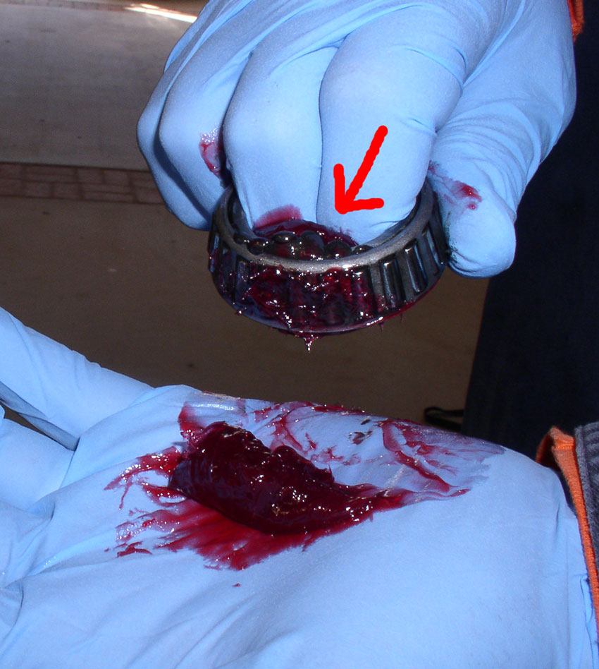
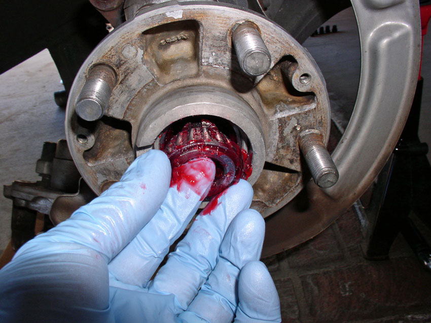
Now it’s time to pack the bearing with grease. Since it can be a messy job, it’s a good idea to pack all 4 bearings at the same time. I don’t have a bearing packer so I used the manual method. Place a medium sized blob of high temperature disc brake wheel bearing grease in the palm of your hand as pictured below. Rubber gloves are a great idea, too!
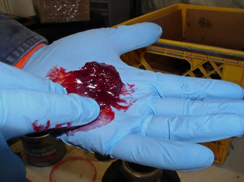
Grab the bearing one or two fingers through the center as pictured below and begin pressing the topside of the bearing into the grease as shown. Lift up and press into the grease again – repeat.
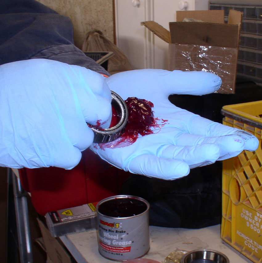
Continue to repeat this process until you see grease emerge from the bottom side of the bearing as shown in the picture below. When you see the grease come through, rotate the bearing in your hand and continue the process until you can see grease coming through the bottom side of the bearing all the way around. When you have finished packing the bearing, move onto the next bearing until all 4 are packed. You can then store all 4 packed bearings in a plastic baggie until you install each one.
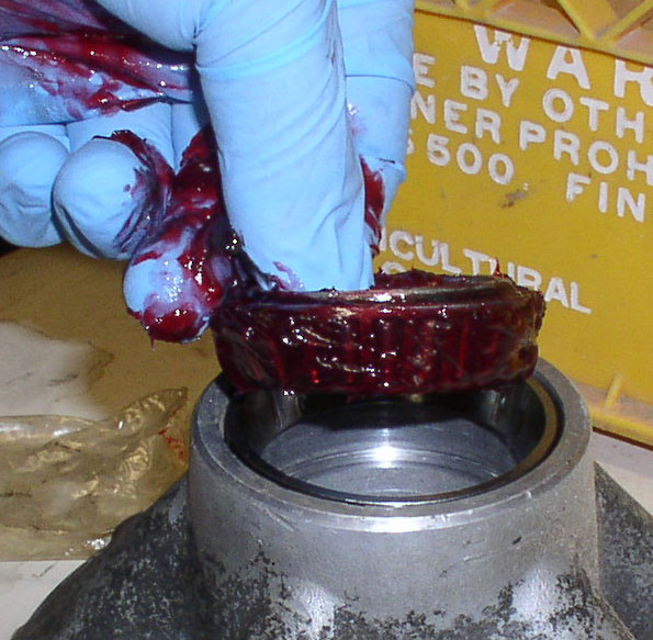
Install the larger, inner bearings first. Before placing the bearing into the hub, I apply a moderate coat of grease to the outer surface of the roller bearings as pictured below. The bearing will be placed into the hub in the same orientation as depicted below. NOTE: **The picture below is a mock up of the install and is for illustration purposes only. You will notice the race is not installed in the hub and is resting at the top for illustration purposes to show the taper of the bearing rollers matches the taper of the race installed in the hub.
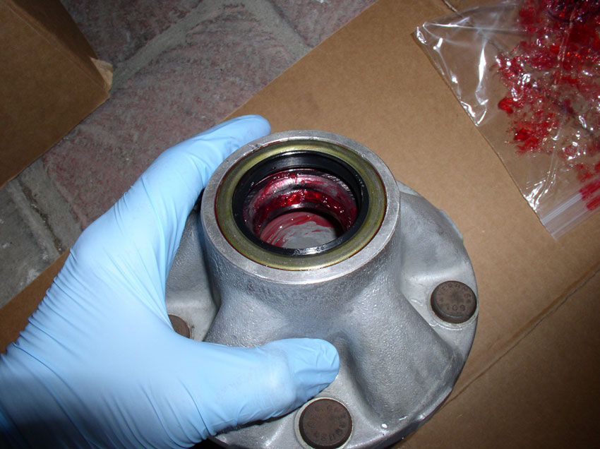
After the inner bearing is placed in the hub, install the inner bearing seal using the bearing seal installer appropriately sized for the seal. I use an installer die that is slightly larger than the seal so that the die will seat against the outer edge of the hub and create a flush mounting for the seal. When installed, the seal should look like the picture below and be flush with the hub rim. Apply a small amount of grease to the inner edge of the bearing to aid in slipping on over the spindle.
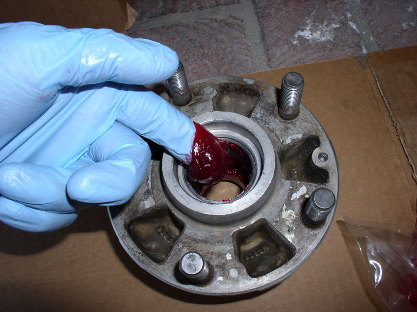
Apply a small amount of grease to the outer race surface – the area the outer roller bearings will rest against.
INSTALLING THE HUB AND ROTOR
Place the hub assembly onto the spindle as shown below. Ensure the hub is fully seated on the spindle by rotating back and forth while pressing onto the spindle. There should only be a small gap between the hub and the dust shield plate at the back of the spindle.
Insert the outer bearing onto the end of the spindle and press it into the hub with your fingers until it is seated against the race in the hub.
Before installing the bearing thrust washer, it is advisable to face sand the washer with 220 grit sandpaper. Sometimes the thrust washer can get a groove in it that may prevent an accurate sliding force when the clamp nut is tightened down. If the faces of the thrust washer are not completely smooth, slide both faces of the washer on the sandpaper until both sides are smooth. Then clean and install the thrust washer. This tip was provided by Stan (Mrmerlin) - THANKS, Stan! Install the bearing thrust washer with the notch aligned with the slot in the spindle as shown below.
Install the clamp nut until it is fully seated against the thrust washer.
I use a pair of channel lock pliers to tighten down the clamp nut about as tight as I can get it while rotating the hub. This will help ensure the hub is fully seated on the spindle. I rotate the hub forwards and backwards several revolutions. I then back off (loosen) the clamp nut with the pliers until….
…I can just barely move the thrust washer with a screwdriver using unassisted human strength.
Then I align the hub slot with the Allen bolt and tighten the clamp nut to 11 ftlbs.
Next, install the rotors. Ensure you have the correct rotor by part number on the Left and Right hub. Each rotor is also stamped with an “L” or “R” on the rotor hat to ease identification. The “L-R” stamping follow the part number stamping. When installing the rotor, be sure to both mating surfaces on the hub and rotor are squeaky clean so the rotor will mount straight and true to the hub. Mount the rotor so the Phillips head screw holes (they are the two holes that are countersunk in the outer face of the rotor hat) align with their screw holes in the hub.
Continued...
Now it’s time to pack the bearing with grease. Since it can be a messy job, it’s a good idea to pack all 4 bearings at the same time. I don’t have a bearing packer so I used the manual method. Place a medium sized blob of high temperature disc brake wheel bearing grease in the palm of your hand as pictured below. Rubber gloves are a great idea, too!
Grab the bearing one or two fingers through the center as pictured below and begin pressing the topside of the bearing into the grease as shown. Lift up and press into the grease again – repeat.
Continue to repeat this process until you see grease emerge from the bottom side of the bearing as shown in the picture below. When you see the grease come through, rotate the bearing in your hand and continue the process until you can see grease coming through the bottom side of the bearing all the way around. When you have finished packing the bearing, move onto the next bearing until all 4 are packed. You can then store all 4 packed bearings in a plastic baggie until you install each one.
Install the larger, inner bearings first. Before placing the bearing into the hub, I apply a moderate coat of grease to the outer surface of the roller bearings as pictured below. The bearing will be placed into the hub in the same orientation as depicted below. NOTE: **The picture below is a mock up of the install and is for illustration purposes only. You will notice the race is not installed in the hub and is resting at the top for illustration purposes to show the taper of the bearing rollers matches the taper of the race installed in the hub.
After the inner bearing is placed in the hub, install the inner bearing seal using the bearing seal installer appropriately sized for the seal. I use an installer die that is slightly larger than the seal so that the die will seat against the outer edge of the hub and create a flush mounting for the seal. When installed, the seal should look like the picture below and be flush with the hub rim. Apply a small amount of grease to the inner edge of the bearing to aid in slipping on over the spindle.
Apply a small amount of grease to the outer race surface – the area the outer roller bearings will rest against.
INSTALLING THE HUB AND ROTOR
Place the hub assembly onto the spindle as shown below. Ensure the hub is fully seated on the spindle by rotating back and forth while pressing onto the spindle. There should only be a small gap between the hub and the dust shield plate at the back of the spindle.
Insert the outer bearing onto the end of the spindle and press it into the hub with your fingers until it is seated against the race in the hub.
Before installing the bearing thrust washer, it is advisable to face sand the washer with 220 grit sandpaper. Sometimes the thrust washer can get a groove in it that may prevent an accurate sliding force when the clamp nut is tightened down. If the faces of the thrust washer are not completely smooth, slide both faces of the washer on the sandpaper until both sides are smooth. Then clean and install the thrust washer. This tip was provided by Stan (Mrmerlin) - THANKS, Stan! Install the bearing thrust washer with the notch aligned with the slot in the spindle as shown below.
Install the clamp nut until it is fully seated against the thrust washer.
I use a pair of channel lock pliers to tighten down the clamp nut about as tight as I can get it while rotating the hub. This will help ensure the hub is fully seated on the spindle. I rotate the hub forwards and backwards several revolutions. I then back off (loosen) the clamp nut with the pliers until….
…I can just barely move the thrust washer with a screwdriver using unassisted human strength.
Then I align the hub slot with the Allen bolt and tighten the clamp nut to 11 ftlbs.
Next, install the rotors. Ensure you have the correct rotor by part number on the Left and Right hub. Each rotor is also stamped with an “L” or “R” on the rotor hat to ease identification. The “L-R” stamping follow the part number stamping. When installing the rotor, be sure to both mating surfaces on the hub and rotor are squeaky clean so the rotor will mount straight and true to the hub. Mount the rotor so the Phillips head screw holes (they are the two holes that are countersunk in the outer face of the rotor hat) align with their screw holes in the hub.
Continued...
01-29-2012, 08:59 PM
#6
Rennlist Member
Thread Starter
Join Date: Sep 2007
Location: Ridgecrest, California
Posts: 1,363
Likes: 0
Received 143 Likes
on
28 Posts
Install the two Phillips head screws and tighten to 7 ftlbs.
Next, check the rotor to ensure it is spinning straight and true. If you don’t have the dial indicator or runout tool, you can do the visual reflection trick I discussed earlier. Pick out a stationary reflection on the back side of the rotor such as the dust shield (shown by the green arrow below). Spin the rotor with one hand and watch the reflection to see if it moves. If it’s steady, you should be good to go. If it moves, you may need to check for debris between the rotor and hub mating surfaces or you may need to use a rubber mallet to tap on the rotor hat to help it fully seat against the hub.
REMOVING THE BRAKE PADS
Place the caliper on top of a cardboard box if not already resting that way. First, remove the brake pad wear sensor by carefully prying up on the plastic end with a flat blade screwdriver as shown below. TIP: Now’s a good time to take a look at the new brake pads and try inserting the brake pad wear sensor into the slot in the new pads. Sometimes the casting on the new pads is rough and will not allow the fragile plastic wear sensor plastic end to fit without forcing it in. This usually results in a cracked plastic end on the end of the sensor wire. To prevent this, I use a small round file on the mounting slot of the new brake pad to smooth out the rough edges and trial fit the sensor plastic end into the slot before mounting the brake pad into the caliper later on.
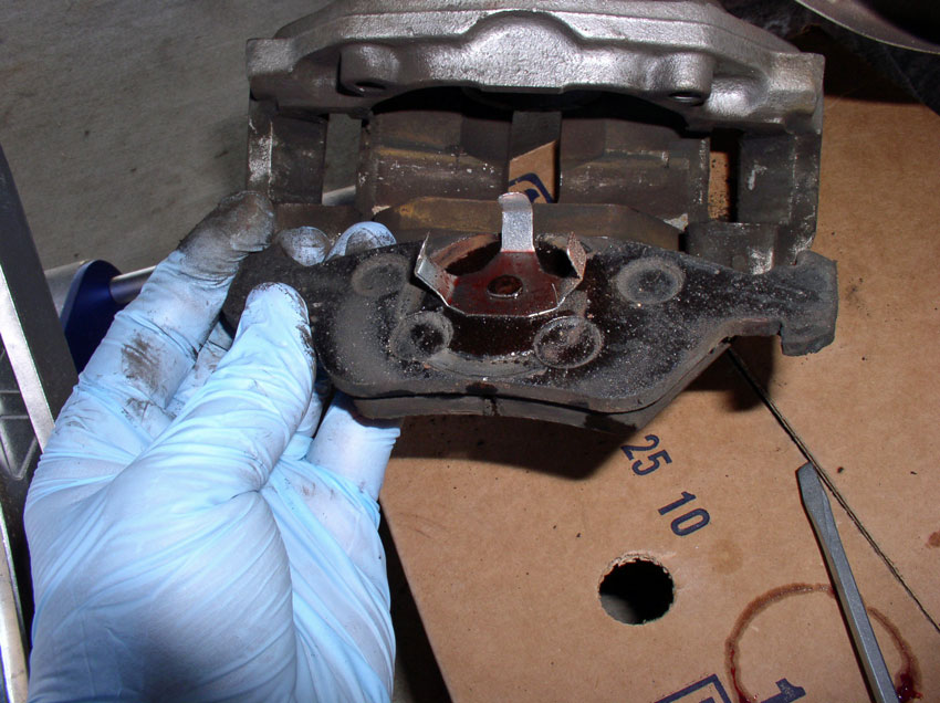
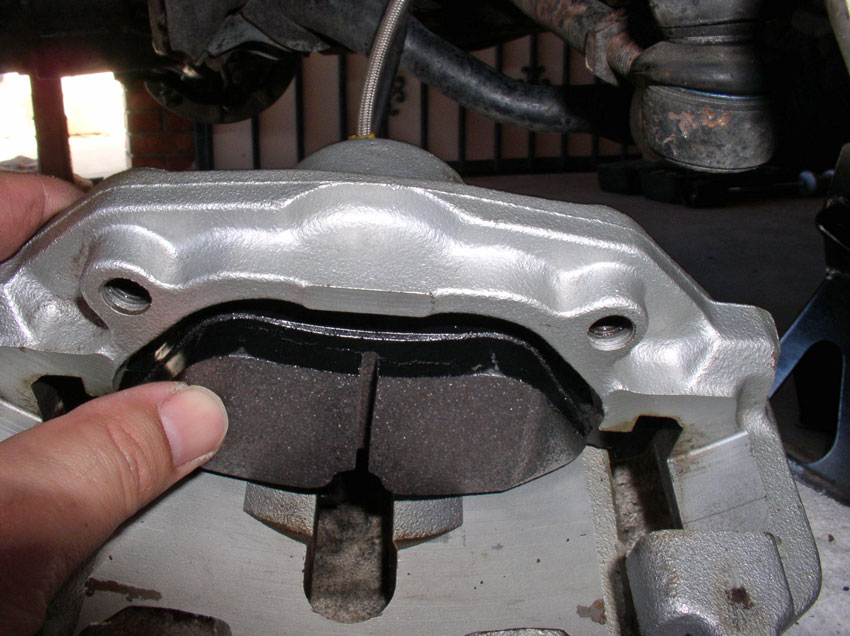
Turn the caliper over and remove the inside brake pad. This type of caliper (also called a floating caliper) has a single piston on the inboard side of the caliper assembly. The inside brake pad is attached to the caliper brake fluid cylinder by the use of spring clips as shown in the picture below. If you are not able to pull out the brake pad by hand, you may choose to use a flat blade screwdriver to pry the pad loose. Once the pad is loose, remove it.
This is what the back side of the inner brake pad looks like when removed.
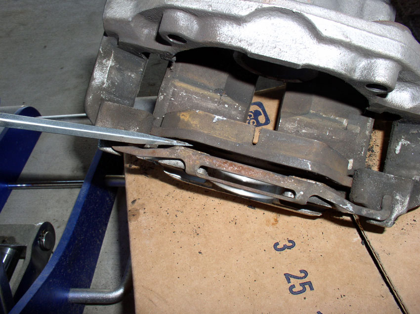
Next, remove the outer brake pad. I used a screwdriver to pry it loose from the caliper as shown.
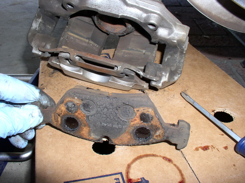
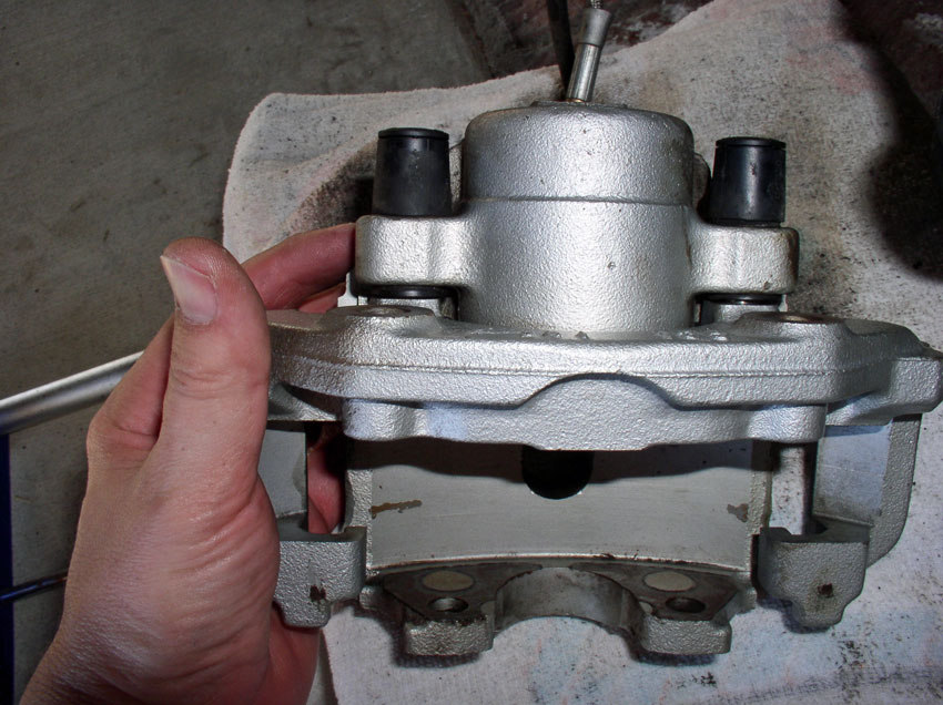
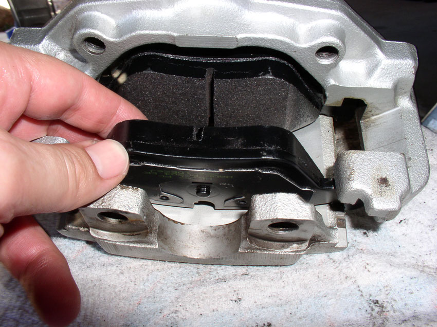
Here’s a picture of the backside of the outer brake pad when removed. At this point, you could choose to press the brake fluid cylinder back into the caliper and simply install the new brake pads and be done. However, you would like to clean up the caliper a little, you can proceed to the next few steps.
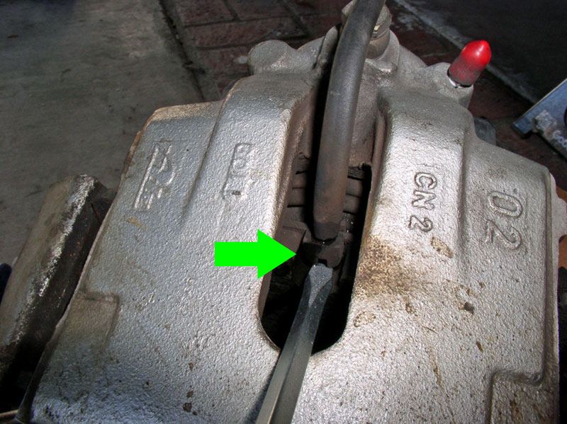
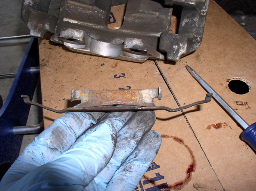
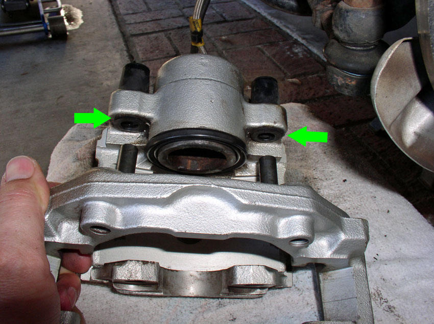
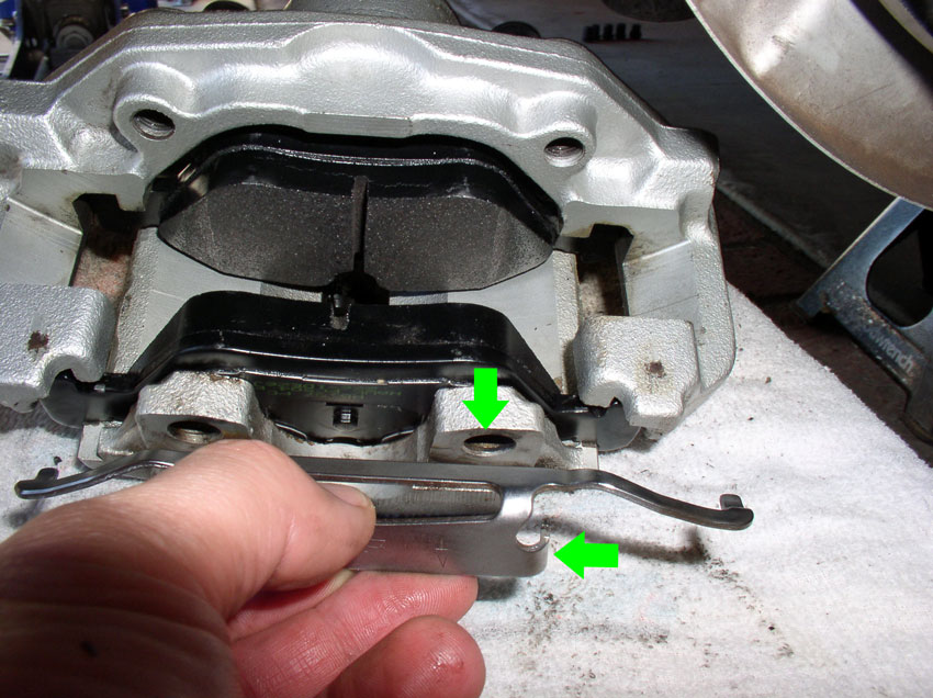
Remove the spring clip that holds the two outer portions of the caliper together. The spring clip has contact points with the caliper at the locations indicated by the green arrows.
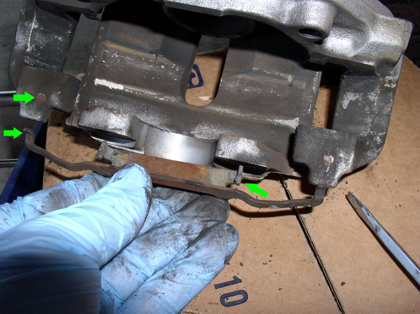
Here’s what the spring clip should look like when removed from the caliper.
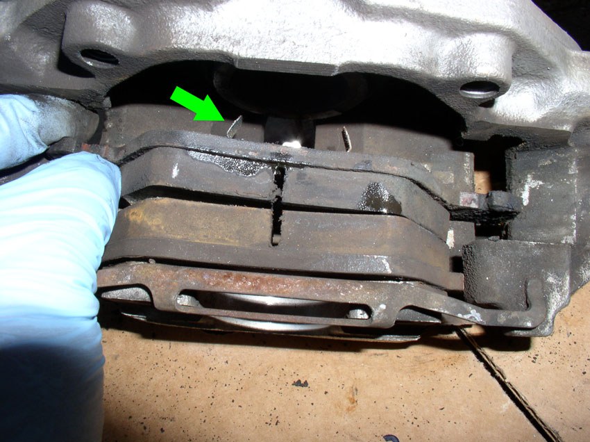
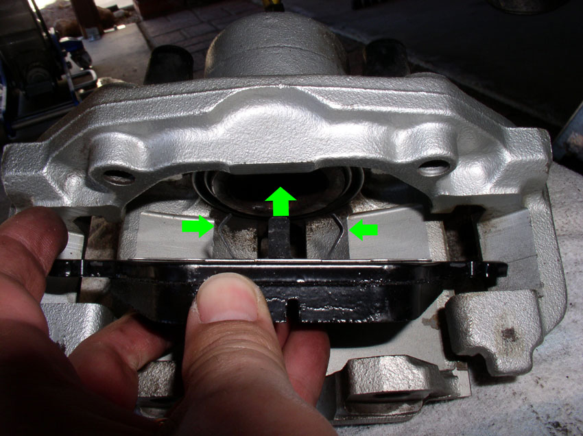
You should now be able to separate the two halves of the floating caliper. Pull the caliper bracket (the piece indicated by the arrows and contains the mounting holes that secure the caliper to the steering knuckle) away from the caliper piston – pulling in the direction of the arrows indicated.
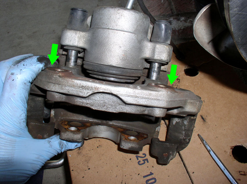
The bracket should come out as shown in the picture below. Now you can clean both parts before reassembly. Since I had painted and clear coated these calipers a few years ago, I simply used water and a nylon brush and rag to clean them up. If you are interested in rebuilding the caliper, now’s a good time to do it as it is only a few more steps away. The rebuild kits usually come with the rubber pin sleeves seen here as well as the brake fluid cylinder dust boot (also visible below) and a brake fluid cylinder seal looks like an O-Ring.
INSTALLING THE BRAKE PADS
If you are going to spray Disc Quiet on the back of your new brake pads, now would be a good time to do it so they can be drying until tacky for the install. Another product worthy of consideration is to apply BG StopSqueal to the friction side of the brake pads. This product is designed to reduce brake squeal. I have not tried the product yet but will try it on my next brake job. THANKS for the tip and recommendation, Greg (blown 87)!
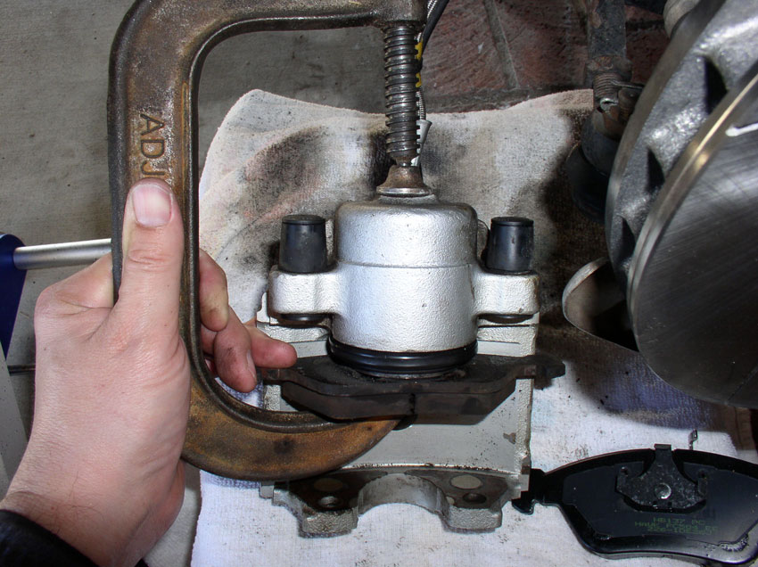
In many cases, before you install the new pads, you will need to compress the brake fluid cylinder in the caliper to allow for the increased thickness of the new pads. I place a used brake pad against the cylinder and use a “C” clamp as shown below to compress the cylinder. I compress the cylinder until it is just about level with the cylinder housing. While you are compressing the cylinder, keep an eye on the brake fluid reservoir in the engine compartment to make sure fluid is not overflowing out the reservoir. If the reservoir in the engine compartment is full and you still need to compress the cylinder, you will need to remove some of the fluid from the reservoir. To prevent contamination of the brake fluid in the reservoir, is like to use a clean paper towel rolled into a tight burrito and dip it into the reservoir to “wick” some of the fluid out. When finished compressing the cylinder, remove the clamp and remove the old brake pad.
Next, you will need to install the fixed bracket to the caliper piston assembly by inserting the slider pins into their rubber sleeves as depicted by the green arrows in the picture below.
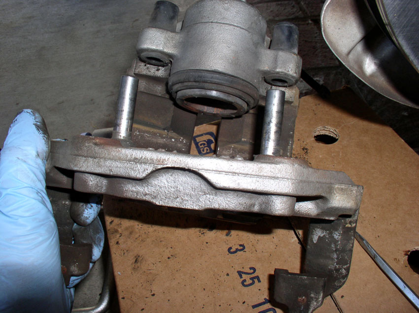
Press the fixed mounting bracket into position until it is fully seated as shown below.
Mount the inner brake pad by aligning the spring clips with the brake fluid cylinder as shown below.
Continued...
Next, check the rotor to ensure it is spinning straight and true. If you don’t have the dial indicator or runout tool, you can do the visual reflection trick I discussed earlier. Pick out a stationary reflection on the back side of the rotor such as the dust shield (shown by the green arrow below). Spin the rotor with one hand and watch the reflection to see if it moves. If it’s steady, you should be good to go. If it moves, you may need to check for debris between the rotor and hub mating surfaces or you may need to use a rubber mallet to tap on the rotor hat to help it fully seat against the hub.
REMOVING THE BRAKE PADS
Place the caliper on top of a cardboard box if not already resting that way. First, remove the brake pad wear sensor by carefully prying up on the plastic end with a flat blade screwdriver as shown below. TIP: Now’s a good time to take a look at the new brake pads and try inserting the brake pad wear sensor into the slot in the new pads. Sometimes the casting on the new pads is rough and will not allow the fragile plastic wear sensor plastic end to fit without forcing it in. This usually results in a cracked plastic end on the end of the sensor wire. To prevent this, I use a small round file on the mounting slot of the new brake pad to smooth out the rough edges and trial fit the sensor plastic end into the slot before mounting the brake pad into the caliper later on.
Turn the caliper over and remove the inside brake pad. This type of caliper (also called a floating caliper) has a single piston on the inboard side of the caliper assembly. The inside brake pad is attached to the caliper brake fluid cylinder by the use of spring clips as shown in the picture below. If you are not able to pull out the brake pad by hand, you may choose to use a flat blade screwdriver to pry the pad loose. Once the pad is loose, remove it.
This is what the back side of the inner brake pad looks like when removed.
Next, remove the outer brake pad. I used a screwdriver to pry it loose from the caliper as shown.
Here’s a picture of the backside of the outer brake pad when removed. At this point, you could choose to press the brake fluid cylinder back into the caliper and simply install the new brake pads and be done. However, you would like to clean up the caliper a little, you can proceed to the next few steps.
Remove the spring clip that holds the two outer portions of the caliper together. The spring clip has contact points with the caliper at the locations indicated by the green arrows.
Here’s what the spring clip should look like when removed from the caliper.
You should now be able to separate the two halves of the floating caliper. Pull the caliper bracket (the piece indicated by the arrows and contains the mounting holes that secure the caliper to the steering knuckle) away from the caliper piston – pulling in the direction of the arrows indicated.
The bracket should come out as shown in the picture below. Now you can clean both parts before reassembly. Since I had painted and clear coated these calipers a few years ago, I simply used water and a nylon brush and rag to clean them up. If you are interested in rebuilding the caliper, now’s a good time to do it as it is only a few more steps away. The rebuild kits usually come with the rubber pin sleeves seen here as well as the brake fluid cylinder dust boot (also visible below) and a brake fluid cylinder seal looks like an O-Ring.
INSTALLING THE BRAKE PADS
If you are going to spray Disc Quiet on the back of your new brake pads, now would be a good time to do it so they can be drying until tacky for the install. Another product worthy of consideration is to apply BG StopSqueal to the friction side of the brake pads. This product is designed to reduce brake squeal. I have not tried the product yet but will try it on my next brake job. THANKS for the tip and recommendation, Greg (blown 87)!
In many cases, before you install the new pads, you will need to compress the brake fluid cylinder in the caliper to allow for the increased thickness of the new pads. I place a used brake pad against the cylinder and use a “C” clamp as shown below to compress the cylinder. I compress the cylinder until it is just about level with the cylinder housing. While you are compressing the cylinder, keep an eye on the brake fluid reservoir in the engine compartment to make sure fluid is not overflowing out the reservoir. If the reservoir in the engine compartment is full and you still need to compress the cylinder, you will need to remove some of the fluid from the reservoir. To prevent contamination of the brake fluid in the reservoir, is like to use a clean paper towel rolled into a tight burrito and dip it into the reservoir to “wick” some of the fluid out. When finished compressing the cylinder, remove the clamp and remove the old brake pad.
Next, you will need to install the fixed bracket to the caliper piston assembly by inserting the slider pins into their rubber sleeves as depicted by the green arrows in the picture below.
Press the fixed mounting bracket into position until it is fully seated as shown below.
Mount the inner brake pad by aligning the spring clips with the brake fluid cylinder as shown below.
Continued...
01-29-2012, 09:13 PM
#7
Rennlist Member
Thread Starter
Join Date: Sep 2007
Location: Ridgecrest, California
Posts: 1,363
Likes: 0
Received 143 Likes
on
28 Posts
Press the pad in until it �snaps� into place against the brake fluid cylinder. You should be able to press it into place by hand.
Line up the outer brake pad and press it into place so it is resting against the floating caliper assembly.
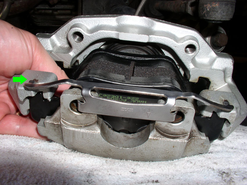
Install the spring clip. Align the 90 degree hooks indicated by the right green arrow with the mounting holes indicated by the upper green arrow. There are left and right hooks and holes to mount.
Place the left and right tangs of the clip assembly on top of the fixed mounting bracket as indicated by the green arrow below.
INSTALLING THE CALIPER
The caliper is now ready to slide onto the rotor. Position the caliper over the rearward edge of the rotor as shown and press in to align the mounting holes.
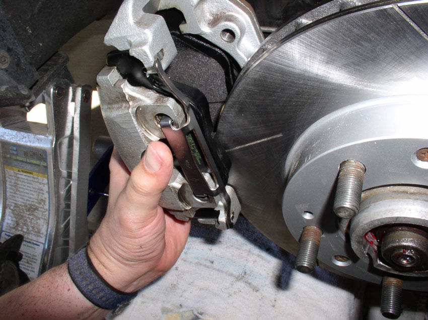
Install the upper caliper mounting bolt and finger tighten. It�s best to leave it finger tightened until you get the lower mounting bolt threaded in place. After the upper bolt is started, install the lower mounting bolt and finger tighten as well.
Torque both upper and lower 19mm caliper mounting bolts to 62 ftlbs.
Install the brake pad wear sensor lead into the inner brake pad slot indicated by the green arrow below. If you filed down the rough edges on the brake pad as suggested earlier, the sensor plastic end should slide right in without a problem.
Almost done! With the brake calipers both installed, you should be able to operate the brake pedal to take up the slack between the brake pads and the rotor surface. The first couple of pressings of the brake pedal will be soft as the brake pads make contact with the rotor surface. Once this is done, you should be able to spin the rotors by hand and listen for a consistent light dragging of the brake pads against the rotor surface. The sound should be consistent all the way around the wheel rotation. If you hear only one scrape at a location and the rest of the travel is silent, then the rotor is not spinning straight and true. Once you are convinced the wheel is running straight and true, you can mount the wheels. Since you cleaned the studs during the baking process, you should apply a very light amount of silver anti-seize to the stud threads before mounting the wheels.
I prefer to mount the hub dust cap with the car on the ground and weight on wheels. That way, when I �tap� the cap into place, the weight of the car is absorbing much of the hammer blows rather than the wheel bearings that were just installed. At this point mount the wheels, lower the car and torque the 19mm wheel lugs to 95 ftlbs
Finally, to mount the dust cap with the wheel on the car and the car on the ground, position the dust cap into the hub and press in enough that it will stay in place. Then I use a large socket that covers most of the surface of the dust cap placed against the dust cap as shown below. Then strike the socket with a hammer until the dust cap is fully seated. You will notice a change in the pitch of the hammer blows as the dust cap seats. When finished, install the wheel center caps.
Before closing the hood of the car and taking it for a test drive, replace the cap on the brake fluid reservoir under the hood making sure the fluid level is between the min and max level marks.
The new brake pads and rotors require a break-in period before they reach their optimum braking characteristics. The WSM recommends a break-in period of about 125 miles (200 Kms) and states hard braking at high speeds should be avoided during the break-in period unless it�s an emergency.
CONGRATULATIONS! You�ve completed the front wheel bearing and brake service. Now go out and enjoy the fruits of your labor!
As always, feel free to comment or add suggestions that improve the overall quality of this write-up. THANKS!
Line up the outer brake pad and press it into place so it is resting against the floating caliper assembly.
Install the spring clip. Align the 90 degree hooks indicated by the right green arrow with the mounting holes indicated by the upper green arrow. There are left and right hooks and holes to mount.
Place the left and right tangs of the clip assembly on top of the fixed mounting bracket as indicated by the green arrow below.
INSTALLING THE CALIPER
The caliper is now ready to slide onto the rotor. Position the caliper over the rearward edge of the rotor as shown and press in to align the mounting holes.
Install the upper caliper mounting bolt and finger tighten. It�s best to leave it finger tightened until you get the lower mounting bolt threaded in place. After the upper bolt is started, install the lower mounting bolt and finger tighten as well.
Torque both upper and lower 19mm caliper mounting bolts to 62 ftlbs.
Install the brake pad wear sensor lead into the inner brake pad slot indicated by the green arrow below. If you filed down the rough edges on the brake pad as suggested earlier, the sensor plastic end should slide right in without a problem.
Almost done! With the brake calipers both installed, you should be able to operate the brake pedal to take up the slack between the brake pads and the rotor surface. The first couple of pressings of the brake pedal will be soft as the brake pads make contact with the rotor surface. Once this is done, you should be able to spin the rotors by hand and listen for a consistent light dragging of the brake pads against the rotor surface. The sound should be consistent all the way around the wheel rotation. If you hear only one scrape at a location and the rest of the travel is silent, then the rotor is not spinning straight and true. Once you are convinced the wheel is running straight and true, you can mount the wheels. Since you cleaned the studs during the baking process, you should apply a very light amount of silver anti-seize to the stud threads before mounting the wheels.
I prefer to mount the hub dust cap with the car on the ground and weight on wheels. That way, when I �tap� the cap into place, the weight of the car is absorbing much of the hammer blows rather than the wheel bearings that were just installed. At this point mount the wheels, lower the car and torque the 19mm wheel lugs to 95 ftlbs
Finally, to mount the dust cap with the wheel on the car and the car on the ground, position the dust cap into the hub and press in enough that it will stay in place. Then I use a large socket that covers most of the surface of the dust cap placed against the dust cap as shown below. Then strike the socket with a hammer until the dust cap is fully seated. You will notice a change in the pitch of the hammer blows as the dust cap seats. When finished, install the wheel center caps.
Before closing the hood of the car and taking it for a test drive, replace the cap on the brake fluid reservoir under the hood making sure the fluid level is between the min and max level marks.
The new brake pads and rotors require a break-in period before they reach their optimum braking characteristics. The WSM recommends a break-in period of about 125 miles (200 Kms) and states hard braking at high speeds should be avoided during the break-in period unless it�s an emergency.
CONGRATULATIONS! You�ve completed the front wheel bearing and brake service. Now go out and enjoy the fruits of your labor!
As always, feel free to comment or add suggestions that improve the overall quality of this write-up. THANKS!
Trending Topics
01-29-2012, 09:54 PM
#9
Three Wheelin'
Wow!!! I'm so glad you chose 928's as your car of choice and not a Buick LeSabre or something else.
In a few years everone can ditch their WSM's.
Thanks Dwayne!
In a few years everone can ditch their WSM's.
Thanks Dwayne!


