HVAC COMPRESSOR RELAY REPAIR PROCEDURE w/PICS
 08-24-2011, 11:43 AM
#61
Electron Wrangler
Lifetime Rennlist
Member
Lifetime Rennlist
Member
Unfortunately Bulvot deleted his posts on this thread that were referenced above.
He proposed a useful technique for this AC clutch case of using your DMM in ammeter mode (as long as it has adequate current capability). With the car off - apply power to the clutch +ve connection via the ammeter from the jump post to detemine the directly powered clutch operating current (it should activate). Note the current.
Then test the total circuit for connectivity and ~equivalent clutch current - start with the Freeze switch since that tests almost back to the HVAC head. At the freeze switch connections, with the car off, power the switch terminal from the jump post through the DMM/ammeter. Try both terminals - should read the same, this should also activate the clutch. If the current reading is within a few % of the previous reading all is good with the whole circuit. This means any issue is likely in the head unit.
If this leads to a much lower reading - then test the intermediate points in the same way - CE panel (supressor - remove to access terminal pin), refrig. pressure switch to determine point of circuit degradation.
Alan
 08-24-2011, 01:07 PM
#62
Electron Wrangler
Lifetime Rennlist
Member
Lifetime Rennlist
Member
Does anybody have the part number of the relay for saving the existing relay in the head unit by installing a relay for the compressor in the engine bay as discussed earlier in the thread? My 91 has a brand new head unit installed by the PO for $1200 and don't want it to blow the relay.
Also what I had previously asked "Has anybody had any experience in repairing the 1,2,3 in the window when you twist the ****? Mine is stuck between 2 & 3 irrespective of where the **** is. The blower works fine and changes speed. "
Thanks
Bilal
Also what I had previously asked "Has anybody had any experience in repairing the 1,2,3 in the window when you twist the ****? Mine is stuck between 2 & 3 irrespective of where the **** is. The blower works fine and changes speed. "
Thanks
Bilal
But what I would do on your S4 model is install the additional relay on the CE panel. Every year has some unused relay slots and if you connect up terminals to these you can add a new relay (standard '53 type or generic Bosch SPST/SPDT relay) on the panel. Adding it here has several advantages - the wiring you need to intercept already goes here to the supressor 'relay', it is out of the weather (engine heat & corrosive env't) mounting is already provided for and it is where all the other relays are.
Yes you have to take out the panel and add the terminals - but you can use standard ford crimp quick connects in these Porsche relay socket cubes.
The clutch connection from the HVAC head is on CE pin H15 - the wiring on the CE panel rear connected to this should be moved to connect to your new relay's terminal 87 (output). Terminal 30 on your new relay should connect via a fuse (pick one of the unused ones) to either the battery bus (30), the X bus (X) or the ignition bus (15) doesn't really matter which. Some of the unused fuses may have connection to one of these bussses already (depends on car options).
Now add a new wire from CE pin H15 to drive your new relay's coil on relay pin 86 & ground the other coil connectio on relay pin 85.
Spare relay socket blocks (unwired) on an 88 should include III, XXVI
Fuse 9 on an 88 should be unused & available for your use - it connects to 15 bus already - input (15) is at the top - output for you to use is at the bottom. its all pretty much plug & play
Alan
BTW - note that the specifics here are for an '88 S4 other years may/will have different relay/fuse & CE connections - but it is doable in a similar manner for all 85+ cars. Earlier models are probably similarly possible - but the CE panel is smaller and there are fewer unused fuses & relay slots depening on optional equipment - so evaluate the wiring diagram for your vehicle.
08-24-2011, 10:05 PM
#63
"Does anybody have the part number of the relay for saving the existing relay in the head unit by installing a relay for the compressor in the engine bay as discussed earlier in the thread?"
Any four pin ('ice cube' type - 30/87/86/85) relay (SPST) can be used.
Less than $5 at any auto parts store. It's a very simple wiring setup:
30 - to a #30 (constant 12 volts)
87 - to compressor clutch
86 - ground
85 - the compressor output of the CCU
This setup eliminates the high (~3/4 amps) current going thru the CCU.
One can always place a fuse in series with either the 30 pin or the 87 pin
to provide relay and wiring protection.
Bottom line: This mod should be a must for any 928 vehicle with a non-updated CCU.
08-25-2011, 02:04 PM
#64
Electron Wrangler
Lifetime Rennlist
Member
Lifetime Rennlist
Member
"Does anybody have the part number of the relay for saving the existing relay in the head unit by installing a relay for the compressor in the engine bay as discussed earlier in the thread?"
Any four pin ('ice cube' type - 30/87/86/85) relay (SPST) can be used.
Less than $5 at any auto parts store. It's a very simple wiring setup:
30 - to a #30 (constant 12 volts)
87 - to compressor clutch
86 - ground
85 - the compressor output of the CCU
This setup eliminates the high (~3/4 amps) current going thru the CCU.
One can always place a fuse in series with either the 30 pin or the 87 pin
to provide relay and wiring protection.
Bottom line: This mod should be a must for any 928 vehicle with a non-updated CCU.
Any four pin ('ice cube' type - 30/87/86/85) relay (SPST) can be used.
Less than $5 at any auto parts store. It's a very simple wiring setup:
30 - to a #30 (constant 12 volts)
87 - to compressor clutch
86 - ground
85 - the compressor output of the CCU
This setup eliminates the high (~3/4 amps) current going thru the CCU.
One can always place a fuse in series with either the 30 pin or the 87 pin
to provide relay and wiring protection.
Bottom line: This mod should be a must for any 928 vehicle with a non-updated CCU.
I still much prefer to add relays and fuses where all the rest are - out of both the weather and underhood environment - as described.
Even if updating the head unit first to correct a fault - I'd rather use a tiny internal relay there (even if pigtailed due to pinout differences) and have my power relay where a large cheap one can fit and be accessed easily.
In this case an (easily found) small SPST relay can be used internal to the headunit for the HVAC Main unit relay pole (pin 8) and the coil contact routed out (pin 6) to feed the external CE panel relay's coil. That is the fix I would do for a failed head unit relay
Alan
08-26-2011, 08:48 AM
#65
Drifting
I agree with Alan. If you do it in the CE than it is as close to factory as possible. I have printed out the wiring diagrams for both the 88 and 91 and will post what I gathered from Alans original suggestion. I am not an electrical wizard therefore would need help to make sure I am doing it right. I also think this should be done even if you have upgraded to a newer head relay.
Anybody has any suggestions for the fans speed indicator fix?
Anybody has any suggestions for the fans speed indicator fix?
08-26-2011, 02:27 PM
#66
Addict
Rennlist Member
Rennlist Member
Bilal, this probably would have best been asked and responded to in a separate thread (not to take this one too far off topic), but... I'll respond here anyway.
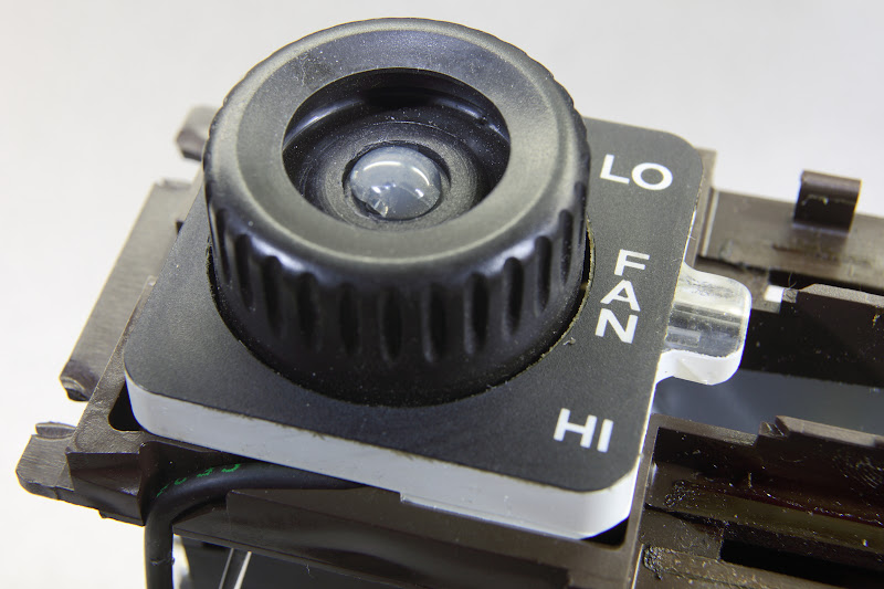
The fan speed indicator is entirely mechanical. I just dug through my photos and have a couple that might help visualize how it works and perhaps might give some hints as to what might prevent it from working correctly.
First, here are the parts off the front of the HVAC control head:

and here's another photo showing the gear wheel #7 attached to the fan speed switch shaft:

Clear plastic gear #8 fits over washer #9, which then are placed over the plastic post adjacent to gear #7 (you can see the grease spot on the second photo where they go). Fan speed indicator #10 then fits over a plastic post that's part of the right end of #4; you have to be pretty careful to keep all this stuff aligned and together as you reassemble everything.
So... if your fan speed indicator isn't working, I'd suspect that something went wrong with #8. Perhaps it broke or (more likely?) the post that #8 and #9 turn on broke.
08-26-2011, 03:15 PM
#67
Electron Wrangler
Lifetime Rennlist
Member
Lifetime Rennlist
Member
Ed - that diagram is worth more than a thousand words!
fantastic! - you are goldmine!
I never dissasassembled mine - but I always just assumed the indicator was a rotating disc under the **** - not a cylinder! - I'm going to look more carefully next time to see how it changes - I obviously wasn't paying enough attention...
Alan
fantastic! - you are goldmine!
I never dissasassembled mine - but I always just assumed the indicator was a rotating disc under the **** - not a cylinder! - I'm going to look more carefully next time to see how it changes - I obviously wasn't paying enough attention...
Alan
09-15-2011, 07:45 AM
#68
Drifting
Thanks Alan for the write up. I am working on my 91 GT and all fuses and relays are in different locations from your car. I have both the wiring diagrams for your and my car but find them very confusing. Can you give me a quick tutorial on how to decipher them?
Thanks
Bilal
Thanks
Bilal
09-15-2011, 01:12 PM
#69
Electron Wrangler
Lifetime Rennlist
Member
Lifetime Rennlist
Member
http://www.928-electrics.com/wiring%...%20primers.htm
Alan
09-15-2011, 07:54 PM
#70
Electron Wrangler
Lifetime Rennlist
Member
Lifetime Rennlist
Member
Thanks Alan for the write up. I am working on my 91 GT and all fuses and relays are in different locations from your car. I have both the wiring diagrams for your and my car but find them very confusing. Can you give me a quick tutorial on how to decipher them?
Thanks
Bilal
Thanks
Bilal
For the 91:
The clutch connection from the HVAC head is on CE pin G21 - the wiring on the CE panel rear connected to this should be moved to connect to your new relay's terminal 87 (output). Terminal 30 on your new relay should connect via a fuse (pick one of the unused ones) to either the battery bus (30), the X bus (X) or the ignition bus (15) doesn't really matter which. Some of the unused fuses may have connection to one of these bussses already (depends on car options).
Now add a new wire from CE pin G21 to drive your new relay's coil on relay pin 86 & ground the other coil connection on relay pin 85.
Spare relay socket blocks (unwired) on a '91 should include III (wired but unused - DRL), VI & XX.
Fuse 31 & 32 on a '91 should be unused & available for your use they are totally unconnected inputs (top) and outputs (bottom). Fuse 43 is also wired for an optional telephone (it also supplies the Cat Monitor) but you should be able to use this assuming you don't have a telephone installed.
Its an ignition supplied fuse with its output on CE pin N24. The stock 7.5A fuse should be OK.
Alan
09-16-2011, 11:49 AM
#71
The plastic pin on #4, which usually/always breaks and that #10 rides on, is not shown.
Improper alignment of #1 & #4 with the CCU case during the assembly process will usually
break this pin. That results in #10 not turning.
Improper alignment of #1 & #4 with the CCU case during the assembly process will usually
break this pin. That results in #10 not turning.
09-16-2011, 12:15 PM
#72
Addict
Rennlist Member
Rennlist Member
I believe the plastic pin you're talking about is the one inside the little part that extends past the main square part of #4; this extension houses #10.
If that's correct, and the plastic pin breaks, it seems like a potential repair would be to drill a hole through the extension piece on #4 where the plastic pin was and insert and glue in a stronger (than plastic) metal pin. Not remembering exactly what it looks like, though, I'm not 100% sure that's doable.
And you're right�you have to be really careful when reassembling these parts and make sure everything is meshing correctly rather than forcing the parts together.
BTW, you can see the clear plastic pin in this photo (look on the right of the #4 piece inside the clear plastic area). Click on the photo for a larger version.
 09-16-2011, 02:21 PM
#73
Rennlist Member
I've had my 928 for 13 years or so, and I never realised there was that number indicator hiding in the little dust filled hole ! Checked it to day and it is working Ok :-)
09-16-2011, 03:23 PM
#74
Three Wheelin'
I replaced my clear plastic pin with an SMD LED and then drilled a small hole through for the wires. Result is the fan **** lights up at night!
Kenny
Kenny
Good point.
I believe the plastic pin you're talking about is the one inside the little part that extends past the main square part of #4; this extension houses #10.
If that's correct, and the plastic pin breaks, it seems like a potential repair would be to drill a hole through the extension piece on #4 where the plastic pin was and insert and glue in a stronger (than plastic) metal pin. Not remembering exactly what it looks like, though, I'm not 100% sure that's doable.
And you're right�you have to be really careful when reassembling these parts and make sure everything is meshing correctly rather than forcing the parts together.
BTW, you can see the clear plastic pin in this photo (look on the right of the #4 piece inside the clear plastic area). Click on the photo for a larger version.
09-16-2011, 07:54 PM
#75
for measuring dc current up to 400 amps w/o going inline try ma-220 ex-tech instruments works great. NO affiliation. just like it and only cost what a good meter would cost,iirc about 120.00
What you just described makes good sense - for the AC circuit primarly - because that happens to be much more accessible for individual connections than most..
However it isn't what you actually said before..
You said..
Now its obvious what you actually meant by that - but the literal reading is quite different..
I point these things out because lots of folks know very little about electrical debug and are looking for good easy techniques - and its important not to set them off down the wrong path. Especially in a generic sense - current probing is hard to even do in most 928 circuits - e.g. multipole connectors and all...
And genericaly for debug it usually isn't actually needed and to me would always be a secondary technique.
I am not an armchair quarterback either - I do spend a lot of time helping people debug challenging things... often their measurement tools & techniques are not so good and it helps to keep it simple... You seem to have a good idea what you are doing - but its really isn't easy to implant that to others...
Alan
I try not to post things that are wrong - But I see no inaccuracies in what I said above...