'87 Intake Removal, Repairs, Installation Procedure (w/pics)
 01-16-2009, 10:15 PM
#1
Rennlist Member
Thread Starter
Join Date: Sep 2007
Location: Ridgecrest, California
Posts: 1,363
Likes: 0
Received 143 Likes
on
28 Posts
Executive Summary:
We bought Virginia ('87) last October and even though she only has 35K miles, she's always had a rough idle particularly when cold (even the PO had been battling the problem). She also had OPG leaks, PS hose leaks, and coolant leaks at the water bridge. So, in November, I decided to get to know the S4 engine since I had not done any major repairs on the S4 (except Motor Mounts on Idaho) and I wanted to learn.
I wanted to post this thread primarily for the other newbies, such as myself, that have never done this job before and would like to have a step-by-step guide. WARNING: this is a long, picture intensive thread - over 630 pictures in this step-by-step guide.
I finished up at the end of December having completed the following:
Intake & cam Covers: Removal, replaced ISV, new hoses, vacuum elbows and manifolds, fuel lines (with Roger's kit), flappy bearings, throttle plate bearings, Powdercoating, new heater valve, knock sensors, all new gaskets
TB/WP: new timing belt & waterpump, accessory belts, A/C Compressor, new o-rings for A/C hoses, expansion valve, receiver drier, rebuild of TB tensioner, Oil pump o-rings, replacement/repair of PS reservior hoses.
Motor Mounts and OPG: R&R of motor mounts and install of silicone OPG with studs (Roger's Kit), replacement of PS hoses to steering rack
HVAC: leak testing and R&R of comb flap and footwell flap diaphrams, blower motor removal, evaporator cleaning, resistor pack removal/adjustment, center console mount repair (Nicole's kit)
Hood: removal and R&R of hood pad (Nicole's kit)
So, after a couple of months and 3400+ pictures later, she's running better than ever and smooth as silk. But only after learning a few surprising things along the way which I will share soon enough. This post deals only with the Intake Job. I plan to post separate threads on the TB/WP work, the MM and OPG, HVAC and Hood repairs to make it easier to search and find this material.
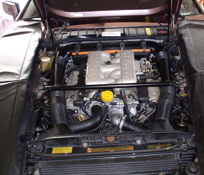
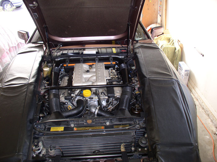
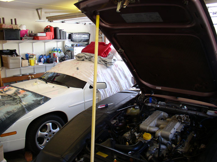
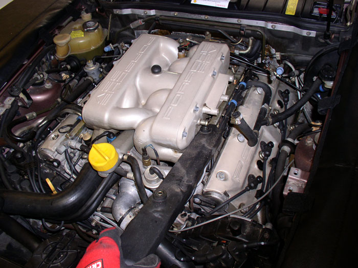
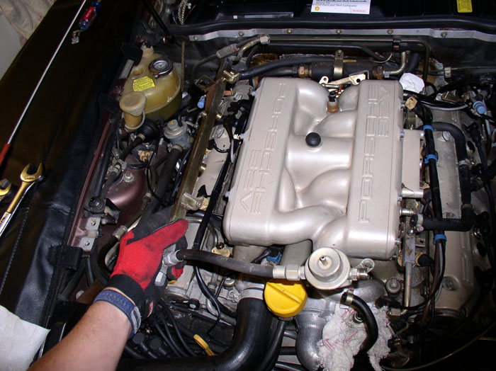
First, the summary eye candy - the before and after.
The pictures don't show it but the paint on the intake and cam covers had become "blotchy" and yellowing. Most of the anodized metal parts appeared to have light salt water spray corrosion from winter driving on snow/salted roads?
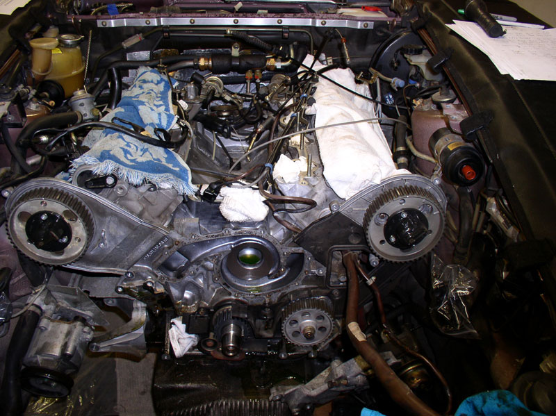
Here I'm into the intake job and half way into the TB/WP task. At this point I began working on the MM and OPG - that job was a lot easier when the engine was already in this state.
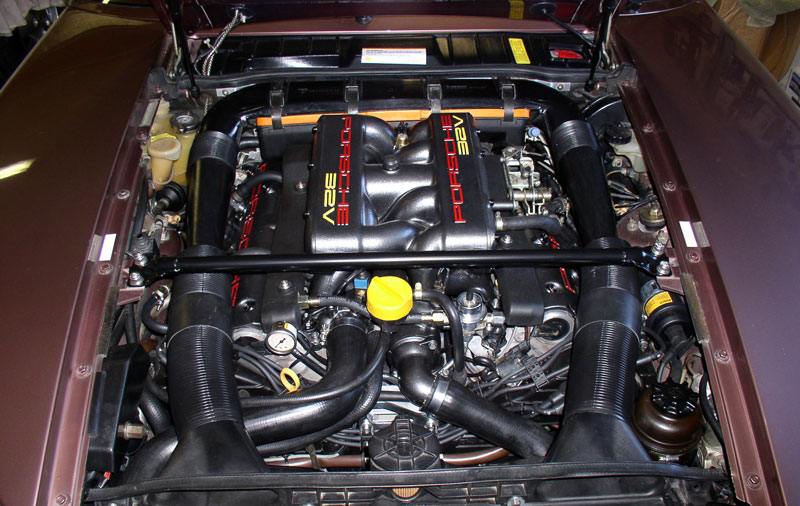
And the finished product. I really liked the powder coating finish for a couple of reasons. The finish is called silver vein and is textured silver/black. The dark color hides the dust and dirt more than the ligher finishes and the textured finish hides the imperfections in the castings. Had to go with yellow on the "32V" to match the oil filler cap and dip stick and other engine decals.
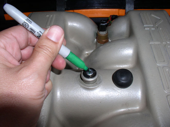
Things that should be looked at closely on the intake job include: Flappy diaphram for leaks, Throttle Position Sensor, Knock Sensors, Hall Sensor, Crank/Flywheel Sensor, Idle Stabilization Valve (ISV), all hoses and connections for false air (intake vacuum) leaks because most of these are only accessable when the intake is off (or partially off) and all of them are easier to address/fix when the intake is off. Before getting started with the tear down, there are a few tests than can be run very simply on a few of these components (flappy diaphram, TPS, and intake vacuum leaks). I ran the flappy and TPS before getting started and also ran them afterward to compare results. I wished I had run the vacuum leak test before getting started to compare before and after but alas, newbism strikes again! First the flappy diaphram test:
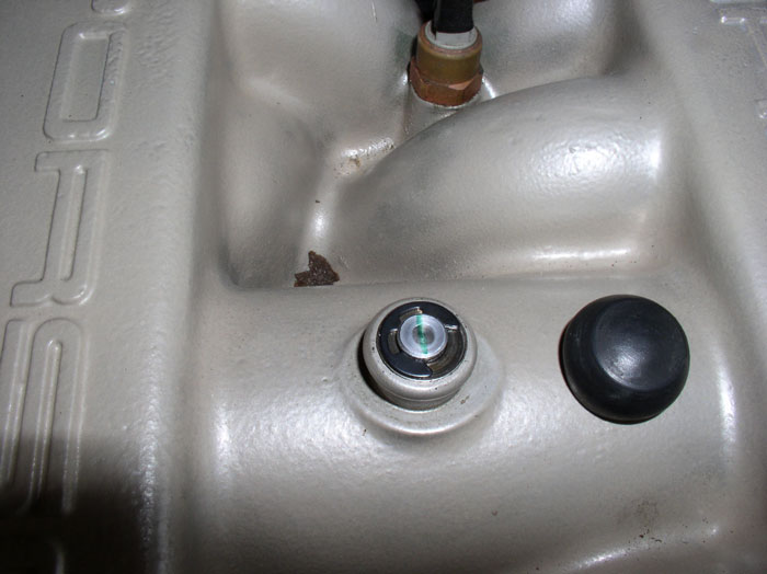
After removing the rubber cap, I marked the top of the flappy assembly with a vertical line.
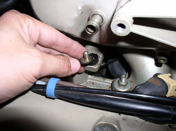
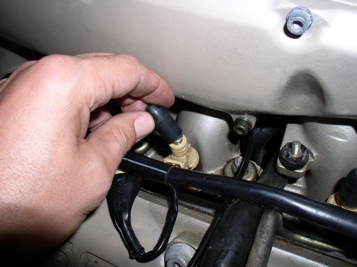
Next, disconnect the flappy vacuum hose at the vacuum solenoid located on the driver's side front cam cover.
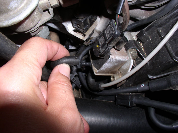
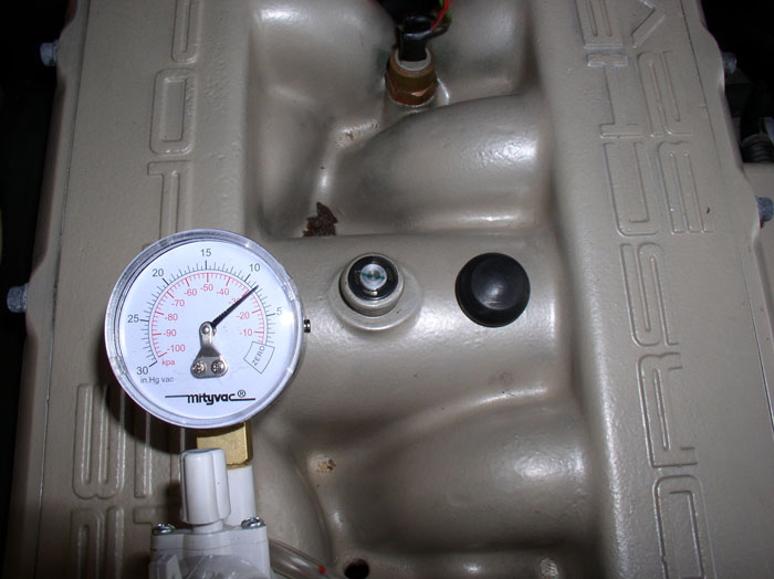
Connect your Mitivac vacuum pump to the elbowconnection....
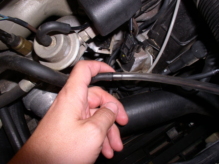
....and note the starting position of the line on the flappy assembly
Pump the vacuum until you see the line move.
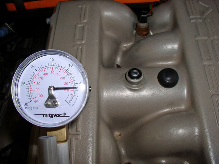
Continue to pump vacuum until you see the line stop moving. It hit the limit at about 8 inches hg. At this point, leave the hose connected and see if the diaphram holds vacuum. If it doesn't hold vacuum or you notice the flappy has difficulty opening all the way (sticking), make a note and you will be able to investigate further when you have the intake off. If it doesn't hold vacuum, don't assume it's the diaphram, it may be vacuum line leaking under the intake. If it works fine, this will provide a baseline for how it was working before taking it apart. When you put it back together and it doesn't work the same or as well, you'll know something is amiss.
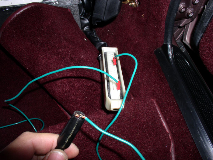
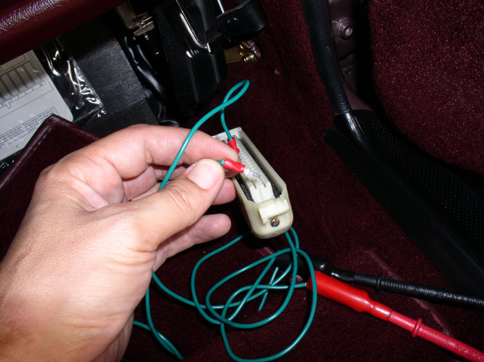
Another test worth performing before teardown is the Throttle position sensor or idle/WOT switch. When working properly, the idle contact informs the computer when your foot is off the accelerator and a different injector/fuel map is to be used. It's most noticeable when your driving at highway speeds and let up off the accelerator. The car deaccelerates significantly faster (until engine rpms drop to about 1100) because the computer shuts off fuel to the injectors. The Wide Open Throttle (WOT) contact, when operating correctly, tells the computer when to provide full fuel enrichment and ignore O2 sensor inputs for maximum performance (hence, the reason it only comes on when you nearly floor the accelerator).
You can perform this test by removing the EZK or LH plugs (after disconnecting the battery negative terminal) and connecting your ohm meter. I fashioned test leads using small blade connectors on one end of electrical wire for insertion into the computer plug connections and the other end to the meter. To test the Idle contact using the EZK plug, connect to pins 18 (ground) and 8. I also tested using the LH plug and you should get the same readings (which I did). The LH pins are 5 (ground) and 2.
The reading should be less than 10 ohms. It's 0.5 ohms here - closed circuit - working here.
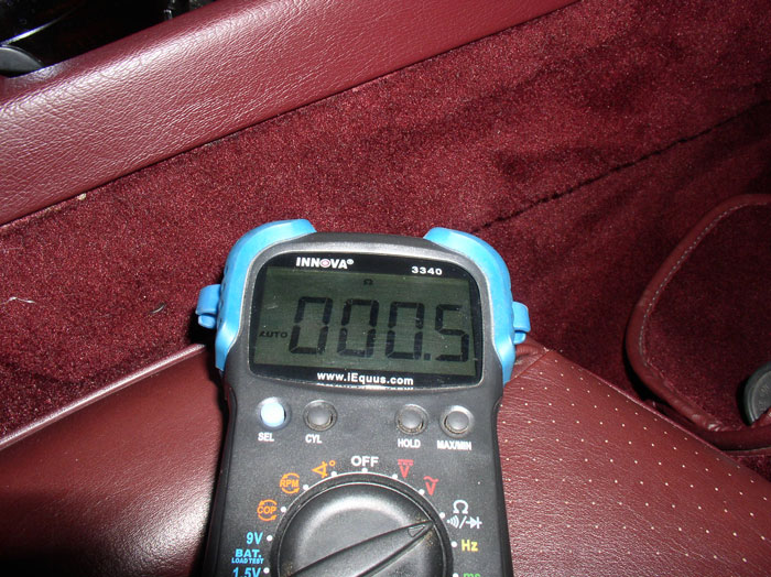
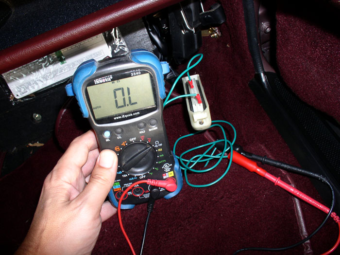
Then press down on the accelerator slightly and the ohm meter should read infinite ohms - open circuit - working here.
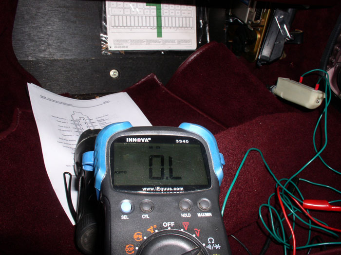
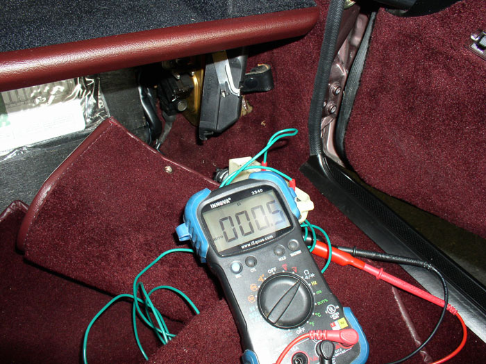
Next, test WOT. Connect to pins 18 (ground) and 26 on the EZK plug. When testing on the LH plug, use pins 5 (ground) and 3.
The reading should be infinite ohms - open circuit - when the accelerator is at rest/idle (works here)
Press the accerator down until it reaches the floor and note when the ohms change. At about 2/3 or 3/4 travel from idle to the floor, the ohms should change to less than 10 ohms (0.5 ohms in this case). Mine closed circuit at 3/4 travel (works as it should). If you don't get these readings, first look at the throttle cable bracket at the side of the intake for loose or slack cables. At first, I had to adjust mine (tighten the accelerator cable) because the WOT wouldn't close until nearly accelerator at the floor. After adjustment, everything worked fine. If you don't get it to work after adjustment, plan to order another TPS.
CAUTION: This thread is Newbie Rated with a lot of pics!
Continued.....
We bought Virginia ('87) last October and even though she only has 35K miles, she's always had a rough idle particularly when cold (even the PO had been battling the problem). She also had OPG leaks, PS hose leaks, and coolant leaks at the water bridge. So, in November, I decided to get to know the S4 engine since I had not done any major repairs on the S4 (except Motor Mounts on Idaho) and I wanted to learn.
I wanted to post this thread primarily for the other newbies, such as myself, that have never done this job before and would like to have a step-by-step guide. WARNING: this is a long, picture intensive thread - over 630 pictures in this step-by-step guide.
I finished up at the end of December having completed the following:
Intake & cam Covers: Removal, replaced ISV, new hoses, vacuum elbows and manifolds, fuel lines (with Roger's kit), flappy bearings, throttle plate bearings, Powdercoating, new heater valve, knock sensors, all new gaskets
TB/WP: new timing belt & waterpump, accessory belts, A/C Compressor, new o-rings for A/C hoses, expansion valve, receiver drier, rebuild of TB tensioner, Oil pump o-rings, replacement/repair of PS reservior hoses.
Motor Mounts and OPG: R&R of motor mounts and install of silicone OPG with studs (Roger's Kit), replacement of PS hoses to steering rack
HVAC: leak testing and R&R of comb flap and footwell flap diaphrams, blower motor removal, evaporator cleaning, resistor pack removal/adjustment, center console mount repair (Nicole's kit)
Hood: removal and R&R of hood pad (Nicole's kit)
So, after a couple of months and 3400+ pictures later, she's running better than ever and smooth as silk. But only after learning a few surprising things along the way which I will share soon enough. This post deals only with the Intake Job. I plan to post separate threads on the TB/WP work, the MM and OPG, HVAC and Hood repairs to make it easier to search and find this material.
First, the summary eye candy - the before and after.
The pictures don't show it but the paint on the intake and cam covers had become "blotchy" and yellowing. Most of the anodized metal parts appeared to have light salt water spray corrosion from winter driving on snow/salted roads?
Here I'm into the intake job and half way into the TB/WP task. At this point I began working on the MM and OPG - that job was a lot easier when the engine was already in this state.
And the finished product. I really liked the powder coating finish for a couple of reasons. The finish is called silver vein and is textured silver/black. The dark color hides the dust and dirt more than the ligher finishes and the textured finish hides the imperfections in the castings. Had to go with yellow on the "32V" to match the oil filler cap and dip stick and other engine decals.
Things that should be looked at closely on the intake job include: Flappy diaphram for leaks, Throttle Position Sensor, Knock Sensors, Hall Sensor, Crank/Flywheel Sensor, Idle Stabilization Valve (ISV), all hoses and connections for false air (intake vacuum) leaks because most of these are only accessable when the intake is off (or partially off) and all of them are easier to address/fix when the intake is off. Before getting started with the tear down, there are a few tests than can be run very simply on a few of these components (flappy diaphram, TPS, and intake vacuum leaks). I ran the flappy and TPS before getting started and also ran them afterward to compare results. I wished I had run the vacuum leak test before getting started to compare before and after but alas, newbism strikes again! First the flappy diaphram test:
After removing the rubber cap, I marked the top of the flappy assembly with a vertical line.
Next, disconnect the flappy vacuum hose at the vacuum solenoid located on the driver's side front cam cover.
Connect your Mitivac vacuum pump to the elbowconnection....
....and note the starting position of the line on the flappy assembly
Pump the vacuum until you see the line move.
Continue to pump vacuum until you see the line stop moving. It hit the limit at about 8 inches hg. At this point, leave the hose connected and see if the diaphram holds vacuum. If it doesn't hold vacuum or you notice the flappy has difficulty opening all the way (sticking), make a note and you will be able to investigate further when you have the intake off. If it doesn't hold vacuum, don't assume it's the diaphram, it may be vacuum line leaking under the intake. If it works fine, this will provide a baseline for how it was working before taking it apart. When you put it back together and it doesn't work the same or as well, you'll know something is amiss.
Another test worth performing before teardown is the Throttle position sensor or idle/WOT switch. When working properly, the idle contact informs the computer when your foot is off the accelerator and a different injector/fuel map is to be used. It's most noticeable when your driving at highway speeds and let up off the accelerator. The car deaccelerates significantly faster (until engine rpms drop to about 1100) because the computer shuts off fuel to the injectors. The Wide Open Throttle (WOT) contact, when operating correctly, tells the computer when to provide full fuel enrichment and ignore O2 sensor inputs for maximum performance (hence, the reason it only comes on when you nearly floor the accelerator).
You can perform this test by removing the EZK or LH plugs (after disconnecting the battery negative terminal) and connecting your ohm meter. I fashioned test leads using small blade connectors on one end of electrical wire for insertion into the computer plug connections and the other end to the meter. To test the Idle contact using the EZK plug, connect to pins 18 (ground) and 8. I also tested using the LH plug and you should get the same readings (which I did). The LH pins are 5 (ground) and 2.
The reading should be less than 10 ohms. It's 0.5 ohms here - closed circuit - working here.
Then press down on the accelerator slightly and the ohm meter should read infinite ohms - open circuit - working here.
Next, test WOT. Connect to pins 18 (ground) and 26 on the EZK plug. When testing on the LH plug, use pins 5 (ground) and 3.
The reading should be infinite ohms - open circuit - when the accelerator is at rest/idle (works here)
Press the accerator down until it reaches the floor and note when the ohms change. At about 2/3 or 3/4 travel from idle to the floor, the ohms should change to less than 10 ohms (0.5 ohms in this case). Mine closed circuit at 3/4 travel (works as it should). If you don't get these readings, first look at the throttle cable bracket at the side of the intake for loose or slack cables. At first, I had to adjust mine (tighten the accelerator cable) because the WOT wouldn't close until nearly accelerator at the floor. After adjustment, everything worked fine. If you don't get it to work after adjustment, plan to order another TPS.
CAUTION: This thread is Newbie Rated with a lot of pics!
Continued.....

The following users liked this post:
cchriss (06-10-2023)
01-16-2009, 10:40 PM
#2
Team Owner
Dwayne, thats a awesome job you did there and the the time spent doing the pictures is also wonderful
01-17-2009, 12:08 AM
#4
Rennlist Member
Thread Starter
Join Date: Sep 2007
Location: Ridgecrest, California
Posts: 1,363
Likes: 0
Received 143 Likes
on
28 Posts
I would recommend testing for vacuum leaks before the teardown so you can compare the results after it's put together. Another purpose of pre-testing is it will allow you to focus on an area for investigation for leaks if you're having trouble pinpointing a leak before taking the intake off. I ended up with leaks after I put it all back together and used the tester below to help find them. Had to take it apart again (several times) to get all the leaks.
I had seen previous posts about making the vacuum/pressure device that allows you to pressurize/depressurize the intake system. Shocki had a great design and pics of one and so did others here. This design is very similar to those. THANKS for sharing!
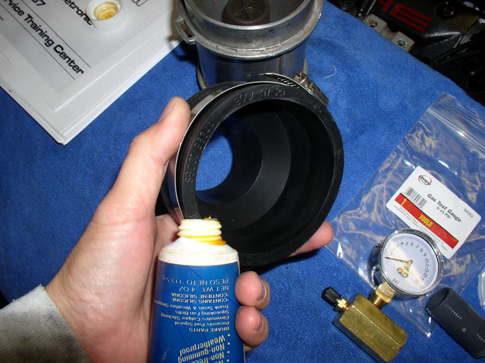
So it was off to Home Depot to find the parts. In total, everything to make this device cost less than $20. You'll only need 4 parts plus some thread sealant (I used teflon tape). 1) the 3" to 2" rubber adapter with clamps, 2) 3/4" PVC male threaded adapter, 3) 2" to 3/4" threaded female PVC plug, 4) low pressure propane/natural gas guage (with 3/4" female threads). Here's what I used:
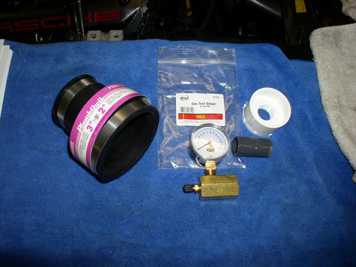
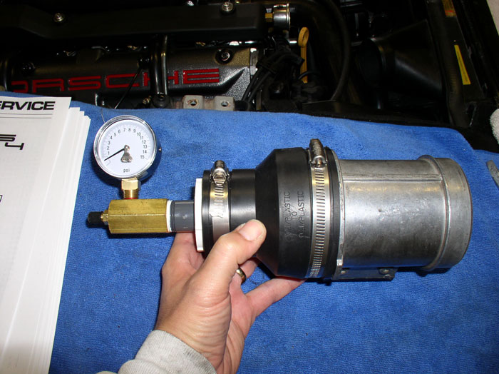
The 3" rubber adapter will be a tight fit on the MAF so you can use some lubricant. I used silicone lube but VERY LITTLE. In fact, after I applied it, I wiped it down with cloth to get any excess off. Too much lube and the rubber adaptor will come off under pressure.
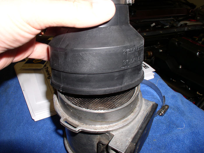
Next, fit the adapter to the MAF. I had an extra MAF sitting around not being used so I just leave it attached to the device permanently. Otherwise, you can remove your MAF and attach it to the adapter.
Then apply teflon tape to the 3/4" threaded adapter and ...
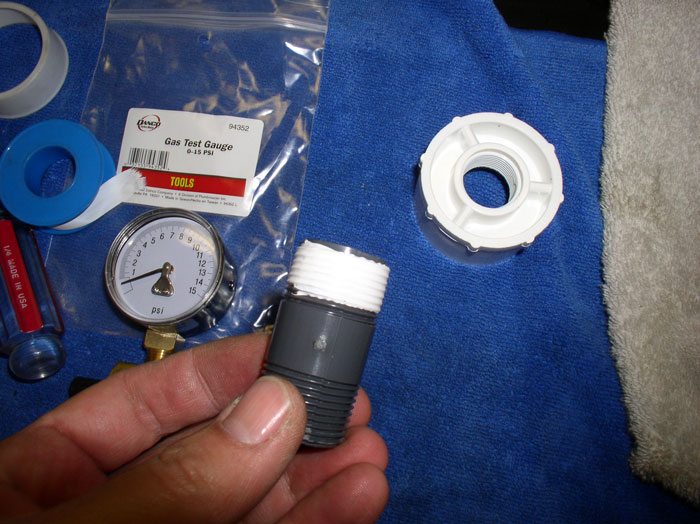
...fit it into the 2" PVC plug and tighten
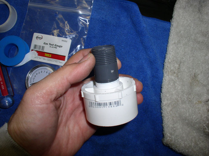
Next, attach the gas guage to the other end of the male PVC threads using teflon tape.
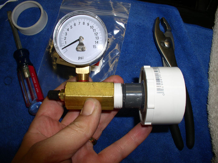
Finally, attach the 2" PVC plug to the 2" end of the rubber adapter and tighten. You are now ready to attach the MAF back to the throttle body and pressurize with an air compressor. I only needed to pressurize to 2.5 PSI and the low pressure guage is great for getting accurate pressure without overpressurizing the system. I had several significant leaks after I put the intake back on - would go from 2.5 PSI to zero in about 10 seconds - car ran like crap. After chasing down all the leaks, going from 2.5 PSI to zero took 4 minutes! Close enough for me!
Now, before going on to the procedure for intake removal, repair and installation, I'd like to recognize the folks that provided great insight and information on how to do this job. I found a writeup by David Chamberland that was TREMENDOUS and I used it as my guid through this process - an excellent piece of work! THANKS David!! There were also numerous posts about flappy bearings, intake leaks, ISV replacement with pics and discussions from several here that I found most helpful to me before getting started. I wanted to say THANKS for the great resource (I can't remember all the names - I'm sure I would miss somebody if I tried.) Of couse thanks to our vendors who supplied all the parts!
Speaking of parts:
After you've tested for and identified leaks, you'll have more information to order the correct parts. I did not have the equipment to test the Hall sensor or the Crank/Flywheel position sensor or the knock sensors but the connections were badly damaged on the knock sensors so they went on the order list. The Hall sensor and crank position sensor connections looked good so I waited until I could dig into it for a closer look before ordering those parts. One good philosophy I usually subscribe to is simply replace everything that is original or broke while you're in there because the car is 20 years old and it's great having peace of mind. That's a philosophy I would recommend if you don't want to get stranded somewhere or don't mind redoing some work 6-12-24 months later. I replaced most things but a few I left alone (such as the hall sensor, the TPS, and the crank position sensor). These looked great to me and the car does only have 35K miles on it. It's more of a personal decision.
With that being said, I've compiled a list of parts for consideration for replacement while your on this job. I supposed you really don't HAVE TO replace anything, if you don't want to. But I tried to prioritize the list in order of things that are STRONGLY recommended to replace on the job down to things that may not need to be replaced and are personal preference.
Here's the list (you should verify part numbers with PET and your vendor because I do make typos - these are for and '87):
Intake to Heads Gasket (2) 928.110.580.02
Throttle Body to Intake Gaskets (2) 928.110.637.02
Intake side cover plate gasket (passenger side) 928.110.713.01
Intake side cover plate gasket (driver's side) 928.110.714.01
Thrust ring (rubber gaskets) for intake nuts (10) 928.110.694.01
Flappy Bearings (2) INA part number HK10122RSFPMDK (Roger has these)
Throttle plate bearings (2) INA Part Number (same as Flappy Bearings)
Cam Cover Gasket Set 928.104.447.09 98 (should come with the following)
Cam cover gasket (2) 928.104.447.09
Rubber Thrust Rings (26) 928.104.115.02
Sealing ring (washers) (12) 900.123.144.30
Spark Plug sealing rings (rubber) (8) 928.104.443.08
Rear coolant port gaskets (2) 928.106.167.01
The kit will come with cam seals/plugs which I did not use in this procedure.
O-rings for cam cover ports for PCV elbows (pass side) and plugs (driver's side) (4) 17mm X 2.5mm
Hoses and Gaskets:
Fuel hose kit from Roger
ISV to Air Guid Cowl 928.110.174.09
ISV to throttle body 928.110.633.00
Front PCV Hose 928.107.445.02
Rear PCV Hose 928.110.432.01
Oil Breather Housing to Air Guide Cowl (Oil filler neck base to throttle body) 928.107.313.02
Oil filler neck to fuel vent solenoid to intake (3-way) 928.107.603.00
Air Guide Cowl to Brake booster venturi 928.110.224.00
Plenum (forward of cable bracket - driver's side) to brake booster venturi 928.110.220.0
Venturi to brake booster 928.110.663.00
7-way vacuum manifold at rear of engine 928.110.441.02
4-way vacuum splitter at brake booster (couldn't find a number but Roger has it)
Vacuum elbows (10) 928.574.717.02
Oil Filler Cap O-Ring 999.701.846.40
For the water bridge:
Water Bridge to Block O-Ring 53mm X 7mm 999.701.627.40
Water Bridge to Heads gasket (2) 928.106.227.00
Thermostat rear seal 928.106.163.00
Thermostat O-Ring front seal 999.701.632.00
Bonded rubber buffer for the fuel rails (attach to intake) (4) 931.110.191.00
Heater water control valve 928.574.573.04
ISV 928.606.161.01
Knock Sensors (2) 911.606.141.00
I ordered/replaced all the parts listed above for this job. If you want peace of mind and want to replace the following, they should also be included:
Throttle Position Sensor 928.606.157.00
Crank Position sensor (couldn't find a part number)
Hall Sensor 944.606.170.02
Flappy vacuum unit under the intake 928.110.160.00
Other supplies you will find useful for this job include:
Silicone lubricant
Sensor safe, oil resistant silicone sealant
Dremel 9901 Tungsten Carbide bit and a Dremel tool, of course
Buffer with wire brush wheel
Auto enamel touch up paint (for detail painting of intake, if desired)
Utility knife
Vacuum pump
long flexible magnetic pick up tool
Most common tools used on this job will be:
8mm, 10mm, 13mm sockets with 3 inch, 6 inch extensions and universal elbow, you'll also need 19mm and 22mm deep sockets
15mm, 17mm, 19mm combination wrenches
4mm, 5mm, 6mm, 8mm allen wrenches both key wrenches and socket versions
Phillips and flat blade screwdrivers
Long neck needle-nose pliers
Car service covers are HIGHLY recommended.
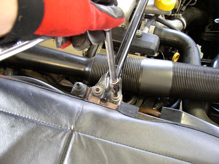
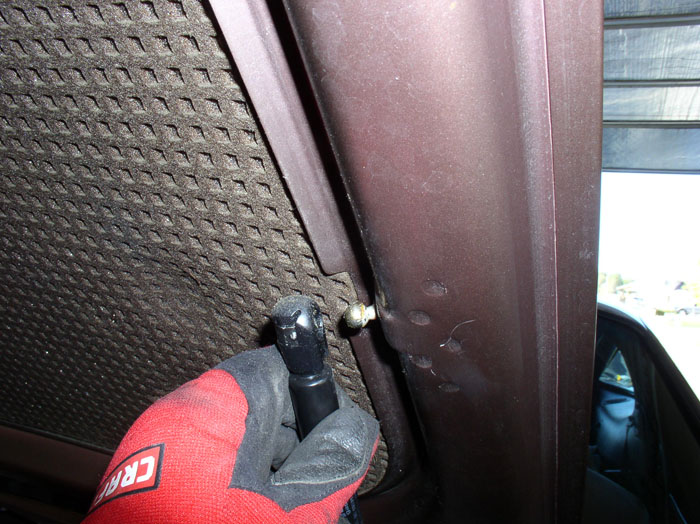
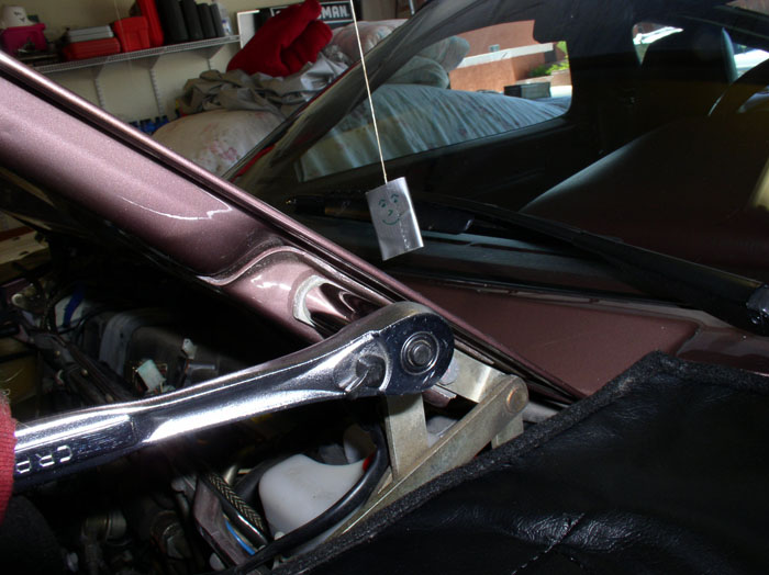
Now, on to the procedure. Since it is likely you will drop bolts and things while working, it's recommended that you raise and support the car and remove the belly pans. Before raising the car, the Workshop Manual recommends removing the engine crossbrace while weight on wheels. So now is a good time to remove the crossbrace. Use a 8mm allen head socket to remove the 4 bolts and remove the crossbrace.
I use PorKen's lift bars and Harbor Freight 6-Ton heavy duty jack stands to raise and support the car - one of the best investments I've made.
Once you have the car raised, disconnect the negative battery cable if you have not already done so from the testing earlier.
First, under the car, remove the rear belly pan.
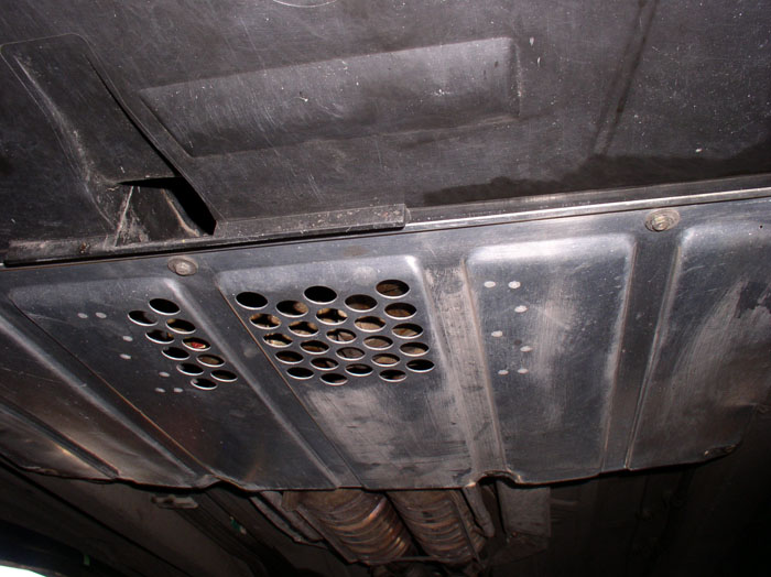
All screws are 8mm hex except for 2 10mm bolts on the forward belly pan.
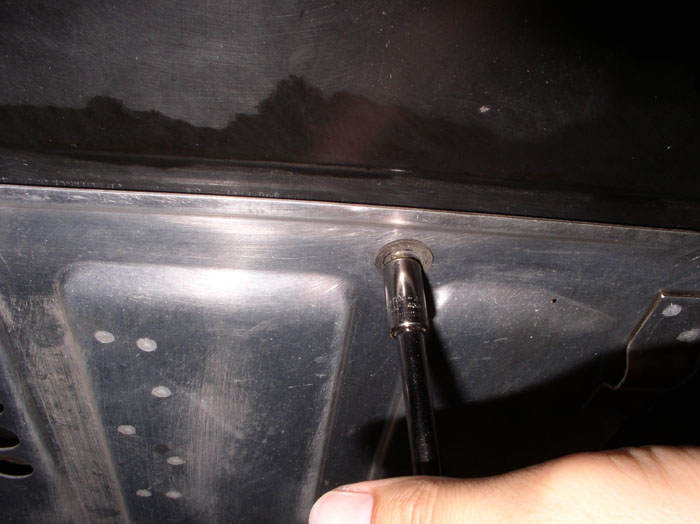
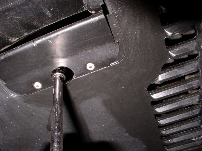
After the rear pan is removed, start on the front pan. Don't forget these two hidden 8mm screws....
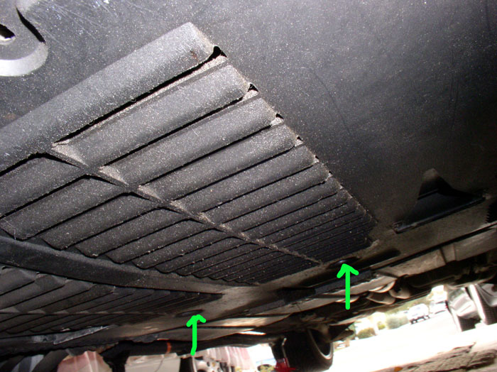
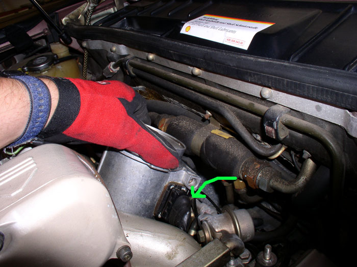
The 2 10mm bolts are located here (green arrows)
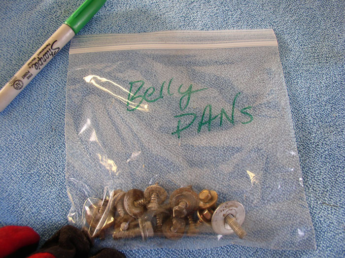
After the front pan is removed, keep the hardware together for the intall. During this job, I bagged all hardware in ziplock baggies with descriptions. I would highly recommend this approach or another that would allow you to keep parts together.
Next, install the service covers.
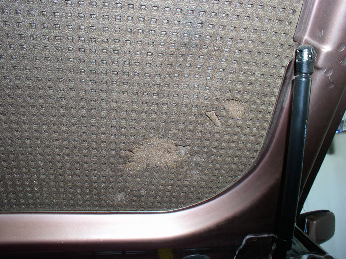
The hood lining was disintegrating so I decided to replace it with one of Nicole's kits. So I removed the hood as it would make the intake job go easier as well as working on the HVAC blower motor and evaporator and resistor pack later.
continued.....
I had seen previous posts about making the vacuum/pressure device that allows you to pressurize/depressurize the intake system. Shocki had a great design and pics of one and so did others here. This design is very similar to those. THANKS for sharing!
So it was off to Home Depot to find the parts. In total, everything to make this device cost less than $20. You'll only need 4 parts plus some thread sealant (I used teflon tape). 1) the 3" to 2" rubber adapter with clamps, 2) 3/4" PVC male threaded adapter, 3) 2" to 3/4" threaded female PVC plug, 4) low pressure propane/natural gas guage (with 3/4" female threads). Here's what I used:
The 3" rubber adapter will be a tight fit on the MAF so you can use some lubricant. I used silicone lube but VERY LITTLE. In fact, after I applied it, I wiped it down with cloth to get any excess off. Too much lube and the rubber adaptor will come off under pressure.
Next, fit the adapter to the MAF. I had an extra MAF sitting around not being used so I just leave it attached to the device permanently. Otherwise, you can remove your MAF and attach it to the adapter.
Then apply teflon tape to the 3/4" threaded adapter and ...
...fit it into the 2" PVC plug and tighten
Next, attach the gas guage to the other end of the male PVC threads using teflon tape.
Finally, attach the 2" PVC plug to the 2" end of the rubber adapter and tighten. You are now ready to attach the MAF back to the throttle body and pressurize with an air compressor. I only needed to pressurize to 2.5 PSI and the low pressure guage is great for getting accurate pressure without overpressurizing the system. I had several significant leaks after I put the intake back on - would go from 2.5 PSI to zero in about 10 seconds - car ran like crap. After chasing down all the leaks, going from 2.5 PSI to zero took 4 minutes! Close enough for me!
Now, before going on to the procedure for intake removal, repair and installation, I'd like to recognize the folks that provided great insight and information on how to do this job. I found a writeup by David Chamberland that was TREMENDOUS and I used it as my guid through this process - an excellent piece of work! THANKS David!! There were also numerous posts about flappy bearings, intake leaks, ISV replacement with pics and discussions from several here that I found most helpful to me before getting started. I wanted to say THANKS for the great resource (I can't remember all the names - I'm sure I would miss somebody if I tried.) Of couse thanks to our vendors who supplied all the parts!
Speaking of parts:
After you've tested for and identified leaks, you'll have more information to order the correct parts. I did not have the equipment to test the Hall sensor or the Crank/Flywheel position sensor or the knock sensors but the connections were badly damaged on the knock sensors so they went on the order list. The Hall sensor and crank position sensor connections looked good so I waited until I could dig into it for a closer look before ordering those parts. One good philosophy I usually subscribe to is simply replace everything that is original or broke while you're in there because the car is 20 years old and it's great having peace of mind. That's a philosophy I would recommend if you don't want to get stranded somewhere or don't mind redoing some work 6-12-24 months later. I replaced most things but a few I left alone (such as the hall sensor, the TPS, and the crank position sensor). These looked great to me and the car does only have 35K miles on it. It's more of a personal decision.
With that being said, I've compiled a list of parts for consideration for replacement while your on this job. I supposed you really don't HAVE TO replace anything, if you don't want to. But I tried to prioritize the list in order of things that are STRONGLY recommended to replace on the job down to things that may not need to be replaced and are personal preference.
Here's the list (you should verify part numbers with PET and your vendor because I do make typos - these are for and '87):
Intake to Heads Gasket (2) 928.110.580.02
Throttle Body to Intake Gaskets (2) 928.110.637.02
Intake side cover plate gasket (passenger side) 928.110.713.01
Intake side cover plate gasket (driver's side) 928.110.714.01
Thrust ring (rubber gaskets) for intake nuts (10) 928.110.694.01
Flappy Bearings (2) INA part number HK10122RSFPMDK (Roger has these)
Throttle plate bearings (2) INA Part Number (same as Flappy Bearings)
Cam Cover Gasket Set 928.104.447.09 98 (should come with the following)
Cam cover gasket (2) 928.104.447.09
Rubber Thrust Rings (26) 928.104.115.02
Sealing ring (washers) (12) 900.123.144.30
Spark Plug sealing rings (rubber) (8) 928.104.443.08
Rear coolant port gaskets (2) 928.106.167.01
The kit will come with cam seals/plugs which I did not use in this procedure.
O-rings for cam cover ports for PCV elbows (pass side) and plugs (driver's side) (4) 17mm X 2.5mm
Hoses and Gaskets:
Fuel hose kit from Roger
ISV to Air Guid Cowl 928.110.174.09
ISV to throttle body 928.110.633.00
Front PCV Hose 928.107.445.02
Rear PCV Hose 928.110.432.01
Oil Breather Housing to Air Guide Cowl (Oil filler neck base to throttle body) 928.107.313.02
Oil filler neck to fuel vent solenoid to intake (3-way) 928.107.603.00
Air Guide Cowl to Brake booster venturi 928.110.224.00
Plenum (forward of cable bracket - driver's side) to brake booster venturi 928.110.220.0
Venturi to brake booster 928.110.663.00
7-way vacuum manifold at rear of engine 928.110.441.02
4-way vacuum splitter at brake booster (couldn't find a number but Roger has it)
Vacuum elbows (10) 928.574.717.02
Oil Filler Cap O-Ring 999.701.846.40
For the water bridge:
Water Bridge to Block O-Ring 53mm X 7mm 999.701.627.40
Water Bridge to Heads gasket (2) 928.106.227.00
Thermostat rear seal 928.106.163.00
Thermostat O-Ring front seal 999.701.632.00
Bonded rubber buffer for the fuel rails (attach to intake) (4) 931.110.191.00
Heater water control valve 928.574.573.04
ISV 928.606.161.01
Knock Sensors (2) 911.606.141.00
I ordered/replaced all the parts listed above for this job. If you want peace of mind and want to replace the following, they should also be included:
Throttle Position Sensor 928.606.157.00
Crank Position sensor (couldn't find a part number)
Hall Sensor 944.606.170.02
Flappy vacuum unit under the intake 928.110.160.00
Other supplies you will find useful for this job include:
Silicone lubricant
Sensor safe, oil resistant silicone sealant
Dremel 9901 Tungsten Carbide bit and a Dremel tool, of course
Buffer with wire brush wheel
Auto enamel touch up paint (for detail painting of intake, if desired)
Utility knife
Vacuum pump
long flexible magnetic pick up tool
Most common tools used on this job will be:
8mm, 10mm, 13mm sockets with 3 inch, 6 inch extensions and universal elbow, you'll also need 19mm and 22mm deep sockets
15mm, 17mm, 19mm combination wrenches
4mm, 5mm, 6mm, 8mm allen wrenches both key wrenches and socket versions
Phillips and flat blade screwdrivers
Long neck needle-nose pliers
Car service covers are HIGHLY recommended.
Now, on to the procedure. Since it is likely you will drop bolts and things while working, it's recommended that you raise and support the car and remove the belly pans. Before raising the car, the Workshop Manual recommends removing the engine crossbrace while weight on wheels. So now is a good time to remove the crossbrace. Use a 8mm allen head socket to remove the 4 bolts and remove the crossbrace.
I use PorKen's lift bars and Harbor Freight 6-Ton heavy duty jack stands to raise and support the car - one of the best investments I've made.
Once you have the car raised, disconnect the negative battery cable if you have not already done so from the testing earlier.
First, under the car, remove the rear belly pan.
All screws are 8mm hex except for 2 10mm bolts on the forward belly pan.
After the rear pan is removed, start on the front pan. Don't forget these two hidden 8mm screws....
The 2 10mm bolts are located here (green arrows)
After the front pan is removed, keep the hardware together for the intall. During this job, I bagged all hardware in ziplock baggies with descriptions. I would highly recommend this approach or another that would allow you to keep parts together.
Next, install the service covers.
The hood lining was disintegrating so I decided to replace it with one of Nicole's kits. So I removed the hood as it would make the intake job go easier as well as working on the HVAC blower motor and evaporator and resistor pack later.
continued.....
01-17-2009, 12:43 AM
#5
Rennlist Member
Thread Starter
Join Date: Sep 2007
Location: Ridgecrest, California
Posts: 1,363
Likes: 0
Received 143 Likes
on
28 Posts
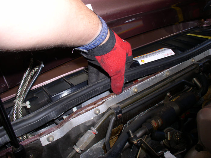
Removing the hood is easier with 2 people but can be done with one which is what I did here. First, remove the wiper motor and blower motor cover by lifting up on the rubber trim side to seperate it from the firewall and pull forward.
Follow the electrical wiring from the hood and disconnect the 3-pin and 2-pin electrical connectors - one wire on each side of the hood.
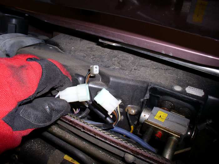
You may have to "un-route" the driver's side electrical wire from under the A/C lines so it is free to move with the hood.
Next, disconnect the two wiper washer fluid supply lines. On mine, one connection was external to the cover plug and the other was internal. Mark one of the lines with tape to indicate whether it was the interal or external connected line so you can connect it back the same way on install.
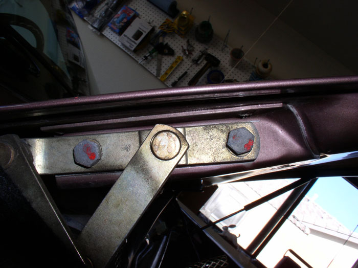
It is best to mark or photograph the orientation of the hood bracket to the hood before disassembly so you can install the hood "in the neighborhood" of where it was originally on install and fine tune from there. Also, don't wash the area around the hood bracket when you have it off. Sometimes the dirt lines will outline the location of othe bracket for you when your ready to install.
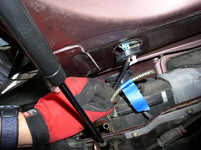
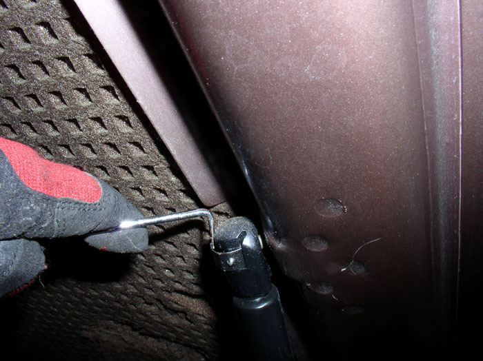
Next, detach the hood shocks. You can use a small screwdriver or a pick tool to pry the spring clamp away from the shock mount. With the clamp pulled away....
...pull the shock away from the hood. Do the same for the other side but be prepared to support the weight of the hood after you disconnect the last shock.
Next, support the hood with a 3'-4' rod or pole
Finally, use a 13mm socket to remove the 4 hood bolts (2 each side). My hood had spacers between the bracket and hood so be prepared to catch those when you remove the bolts. If you're doing this by yourself, I place towels between the hood and exposed fender locations such as near the windshield and at the front hood latch so as not to scratch any body paint. You will need to support the hood with one hand while removing the last bolts with the other.
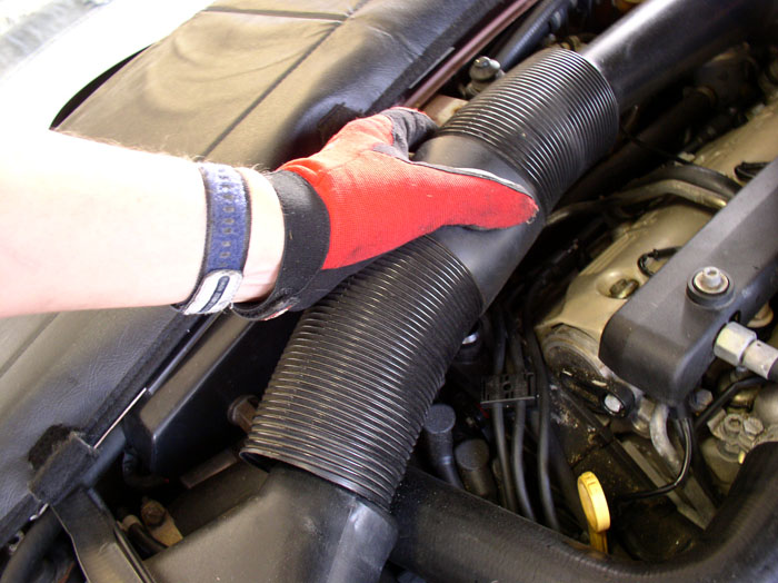
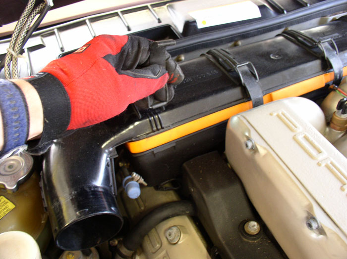
Remove the intake air tubes.
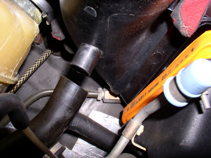
Remove the air filter cover.....
...don't forget the air pump feed hose underneath the passenger side of the air filter cover. You can loosen the clamp with a screwdriver first. Then remove the cover and air filter.
The air box that houses the filter is secured by 4 10mm nuts - 2 on each side. Remove these. Two of the studs are connected to the fuel pressure regulator and dampers bracket underneath the air box and the other 2 are connected to the exhaust tester tube brackets. After the nuts have been removed, you can lift out the air box.
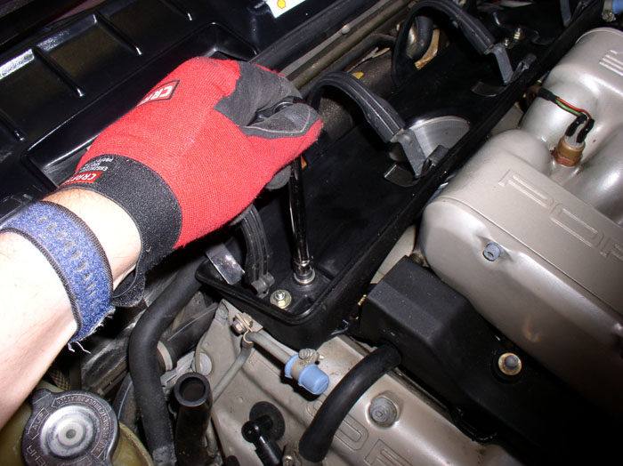
Remove the MAF. You may need to loosen the band clamp at the air guide cowl using a stubby screwdriver or small socket with universal elbow. Mine came out without having to loosen the clamp. Next, disconnect the MAF sensor plug on the dirver's side. Rock it back and forth while pulling outward.
continued......
Follow the electrical wiring from the hood and disconnect the 3-pin and 2-pin electrical connectors - one wire on each side of the hood.
You may have to "un-route" the driver's side electrical wire from under the A/C lines so it is free to move with the hood.
Next, disconnect the two wiper washer fluid supply lines. On mine, one connection was external to the cover plug and the other was internal. Mark one of the lines with tape to indicate whether it was the interal or external connected line so you can connect it back the same way on install.
It is best to mark or photograph the orientation of the hood bracket to the hood before disassembly so you can install the hood "in the neighborhood" of where it was originally on install and fine tune from there. Also, don't wash the area around the hood bracket when you have it off. Sometimes the dirt lines will outline the location of othe bracket for you when your ready to install.
Next, detach the hood shocks. You can use a small screwdriver or a pick tool to pry the spring clamp away from the shock mount. With the clamp pulled away....
...pull the shock away from the hood. Do the same for the other side but be prepared to support the weight of the hood after you disconnect the last shock.
Next, support the hood with a 3'-4' rod or pole
Finally, use a 13mm socket to remove the 4 hood bolts (2 each side). My hood had spacers between the bracket and hood so be prepared to catch those when you remove the bolts. If you're doing this by yourself, I place towels between the hood and exposed fender locations such as near the windshield and at the front hood latch so as not to scratch any body paint. You will need to support the hood with one hand while removing the last bolts with the other.
Remove the intake air tubes.
Remove the air filter cover.....
...don't forget the air pump feed hose underneath the passenger side of the air filter cover. You can loosen the clamp with a screwdriver first. Then remove the cover and air filter.
The air box that houses the filter is secured by 4 10mm nuts - 2 on each side. Remove these. Two of the studs are connected to the fuel pressure regulator and dampers bracket underneath the air box and the other 2 are connected to the exhaust tester tube brackets. After the nuts have been removed, you can lift out the air box.
Remove the MAF. You may need to loosen the band clamp at the air guide cowl using a stubby screwdriver or small socket with universal elbow. Mine came out without having to loosen the clamp. Next, disconnect the MAF sensor plug on the dirver's side. Rock it back and forth while pulling outward.
continued......
Trending Topics
01-17-2009, 01:34 AM
#9
Rennlist Member
Thread Starter
Join Date: Sep 2007
Location: Ridgecrest, California
Posts: 1,363
Likes: 0
Received 143 Likes
on
28 Posts
In order to remove the cables bracket from the intake, you will need to disconnect the accelerator cable from the cables bracket. Pull the ball connector at the end of the cable away from the bracket.
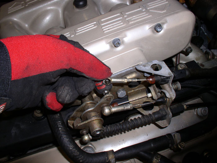
Then depress the tabs on the accelerator cable plastic lock and push the plastic lock back out the bracket - toward the windshield. I used a screwdriver to work one side out first then the other.
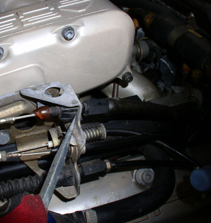
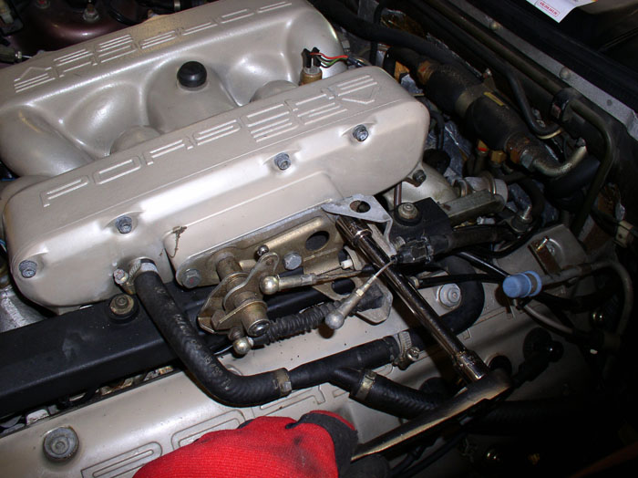
You now have access to the 3 13mm bolts that hold the bracket to the intake. Remove these next and place the bracket out of the way (either on the cam cover or back behind the intake (where the MAF use to be)
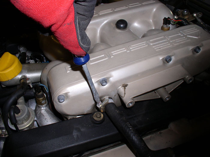
Next, remove the intake hose to brake booster venturi using a screwdriver.
Now, remove the fuel rail covers. Each is secured with 2 5mm allen head bolts. Remove these bolts. The passenger side rail will simply lift up to remove. While....
...the driver's side cover requires you to slide it out toward the front of the car. The insulation around the fuel rail was all missing on Virginia.
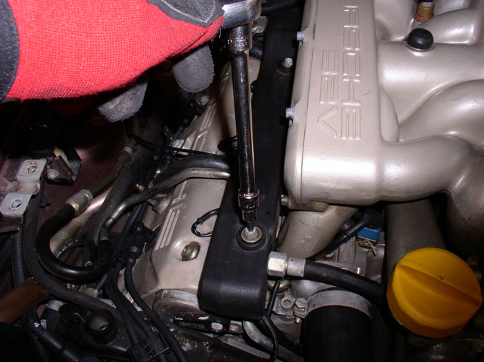
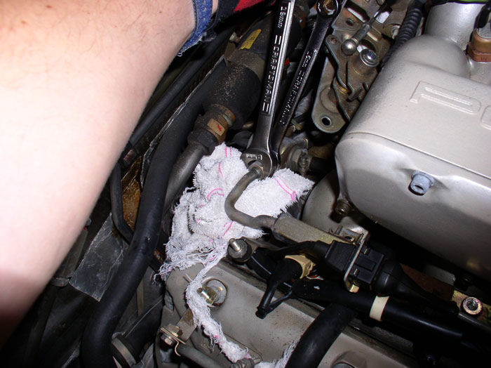
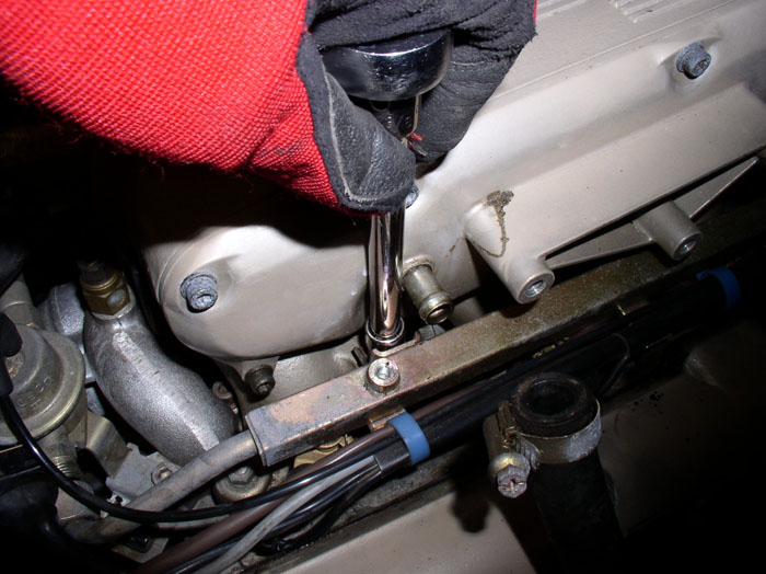
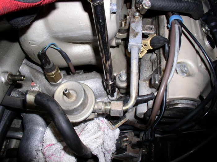
Next, disconnect the fuel rails. First, the the driver's side front. Place a thick, absorbant towel under the connection to catch fuel left in the lines. It's best to wait several hours since the car was run to disconnect the fuel lines so the pressure will go down. At the fuel pressure damper use a 15mm wrench to counterhold while using a 19mm wrench to loosen and disconnect. Loosen slowly in case the lines are still pressurized.
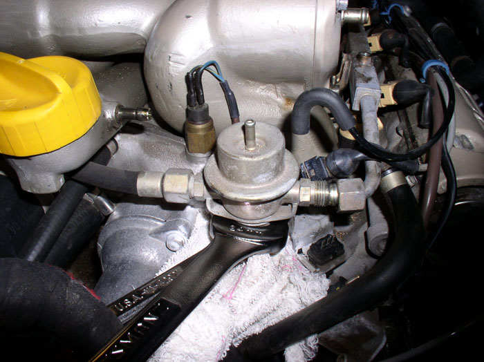
Disconnect the fuel rail at the rear fuel pressure damper (driver's side) and the fuel pressure regulator (passenger side shown below). Using 15mm and 19mm wrenches again. Use a towel to catch escaping fuel.
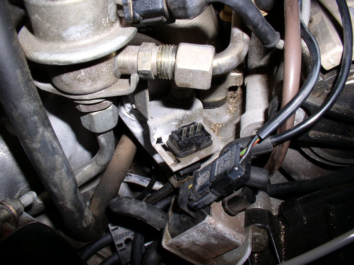
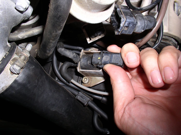
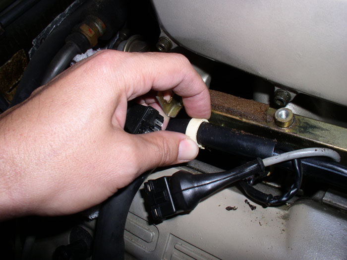
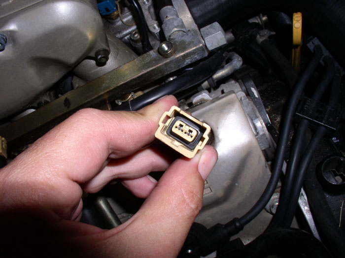
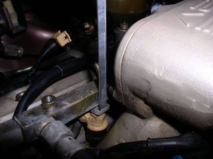
Disconnect the passenger side knock sensor from the harnes and fuel rail. You can see that my sensor plug had melted and was no longer holding together.
Disconnect the front knock sensor plug from the wiring harness. Same story here on mine with the melted plug.
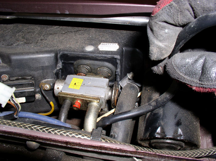
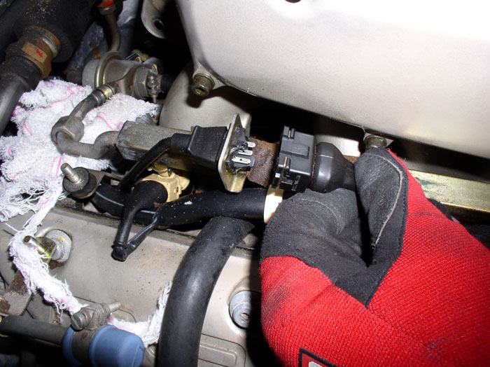
Disconnect the electrical lead to the flappy vacuum solenoid.
And the vacuum elbow from the solenoid to the flappy diaphram.
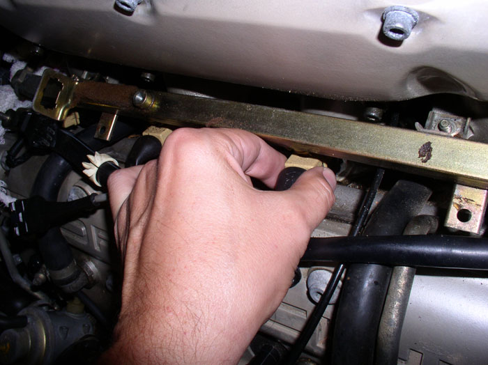
Remove the fuel rail mounting nuts located at the intake runners. Use a 10mm socket on the nuts.
Since these are in a hard to reach place, you can magnetize your socket to make sure the nut comes up with your socket. Or you can use your flexible magnetic pick up tool to fish the nut out.
The rear nuts are easier to reach without fancy tricks.
continued......
Then depress the tabs on the accelerator cable plastic lock and push the plastic lock back out the bracket - toward the windshield. I used a screwdriver to work one side out first then the other.
You now have access to the 3 13mm bolts that hold the bracket to the intake. Remove these next and place the bracket out of the way (either on the cam cover or back behind the intake (where the MAF use to be)
Next, remove the intake hose to brake booster venturi using a screwdriver.
Now, remove the fuel rail covers. Each is secured with 2 5mm allen head bolts. Remove these bolts. The passenger side rail will simply lift up to remove. While....
...the driver's side cover requires you to slide it out toward the front of the car. The insulation around the fuel rail was all missing on Virginia.
Next, disconnect the fuel rails. First, the the driver's side front. Place a thick, absorbant towel under the connection to catch fuel left in the lines. It's best to wait several hours since the car was run to disconnect the fuel lines so the pressure will go down. At the fuel pressure damper use a 15mm wrench to counterhold while using a 19mm wrench to loosen and disconnect. Loosen slowly in case the lines are still pressurized.
Disconnect the fuel rail at the rear fuel pressure damper (driver's side) and the fuel pressure regulator (passenger side shown below). Using 15mm and 19mm wrenches again. Use a towel to catch escaping fuel.
Disconnect the passenger side knock sensor from the harnes and fuel rail. You can see that my sensor plug had melted and was no longer holding together.
Disconnect the front knock sensor plug from the wiring harness. Same story here on mine with the melted plug.
Disconnect the electrical lead to the flappy vacuum solenoid.
And the vacuum elbow from the solenoid to the flappy diaphram.
Remove the fuel rail mounting nuts located at the intake runners. Use a 10mm socket on the nuts.
Since these are in a hard to reach place, you can magnetize your socket to make sure the nut comes up with your socket. Or you can use your flexible magnetic pick up tool to fish the nut out.
The rear nuts are easier to reach without fancy tricks.
continued......
 01-17-2009, 02:15 AM
#11
Rennlist Member
Thread Starter
Join Date: Sep 2007
Location: Ridgecrest, California
Posts: 1,363
Likes: 0
Received 143 Likes
on
28 Posts
Remove the harness clips from the fuel rails. These tend to be very brittle and will easily break. All of mine were still in tact but broke when I tried to remove them.
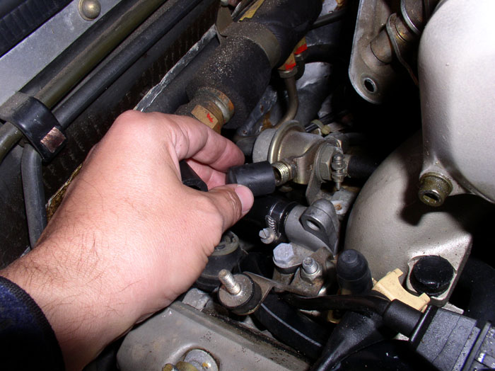
Next, disconnect the fuel injector harness connectors at each injector. I simply used my thumb and index finger to grip and pulled toward me while rocking side to side.
Oddly enough, these injector connectors had an unusual wire clip. Most that I have seen had curved ends on them that secured them to the plastic housing. These did not and therefore, fell out of the connector housing easily. Use the magnectic pick up tool to fish them out if they fall out. As a precaution, I removed any clips that did not fall out because I didn't want them falling into the heads while removing the intake later. Store them together in a baggie.
Inspect the injector connector gasket for condition.
Next, remove the oil filler neck hose (a 3-way hose) that leads to the fuel vent solenoid and the other end leads to the intake.
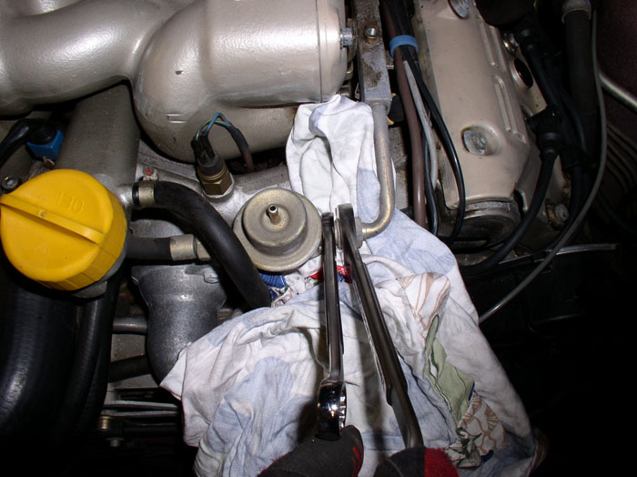
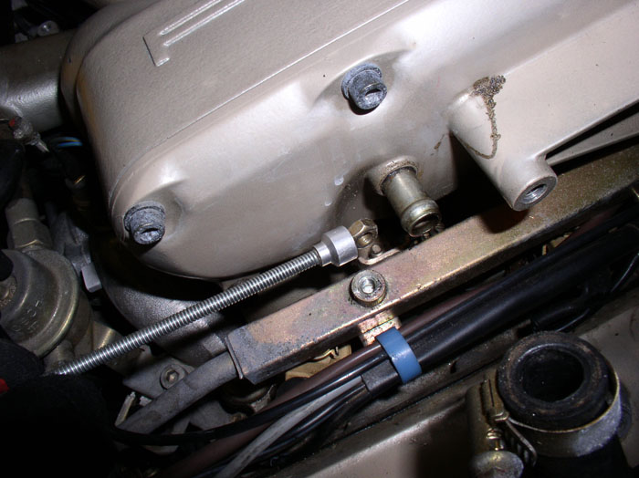
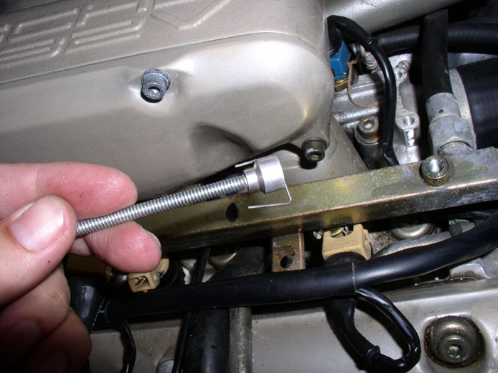
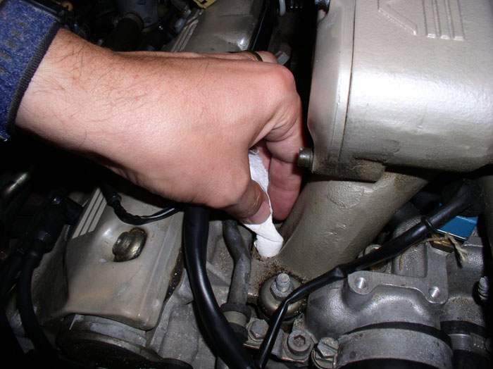
Disconnect the front fuel pressure damper using a 24mm wrench to counterhold and a 19mm wrench to loosen the fuel line nut. Use a towel to catch escaping fuel.
Remove the one allen bolt that holds down the fuel pressure damper bracket to the water bridge. It takes a 6mm allen socket.
The fuel rails are now ready to pull out. There's a couple of ways you can do this. One way is to simply lift up the rails with the injectors attached. Sometimes the injectors can be firmly attached to the intake so will require some care to pry up. Another way that I have never tried before but tried this time is to remove the clips that secure the fuel injector to the rail and lift the rail up leaving the fuel injectors behind. To use this method, pry the injector retaining clips away from the rail using a flat blade screwdriver. Remove all eight this way.
The fuel rail can then be lifted out without much upward force required.
I left the front fuel hose attached to the pressure damper because at the time, I wasn't sure if I was going to replace the fuel lines. Later, I decided to replace the lines and disconnected the hose.
Bag the fuel rails to prevent dirt from contaminating the rails and pressure damper.
The fuel rail mounts to the intake were hardened and split in two. Only one was left in tact. So all 4 were replaced.
If you are not planning on sending your injectors off to be cleaned, you can cap the injectors with vacuum plugs to project them from getting dirt in them.
Also, cap the Fuel Pressure Regulator and rear pressure damper with vacuum plugs.
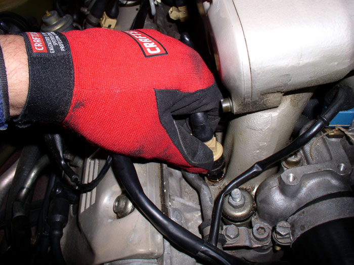
I found fuel injectors easier to remove one a time since they were firmly planted rather then 4 at a time with the rail. Grip the injector and work side to side while pulling upward.
continued.....
Next, disconnect the fuel injector harness connectors at each injector. I simply used my thumb and index finger to grip and pulled toward me while rocking side to side.
Oddly enough, these injector connectors had an unusual wire clip. Most that I have seen had curved ends on them that secured them to the plastic housing. These did not and therefore, fell out of the connector housing easily. Use the magnectic pick up tool to fish them out if they fall out. As a precaution, I removed any clips that did not fall out because I didn't want them falling into the heads while removing the intake later. Store them together in a baggie.
Inspect the injector connector gasket for condition.
Next, remove the oil filler neck hose (a 3-way hose) that leads to the fuel vent solenoid and the other end leads to the intake.
Disconnect the front fuel pressure damper using a 24mm wrench to counterhold and a 19mm wrench to loosen the fuel line nut. Use a towel to catch escaping fuel.
Remove the one allen bolt that holds down the fuel pressure damper bracket to the water bridge. It takes a 6mm allen socket.
The fuel rails are now ready to pull out. There's a couple of ways you can do this. One way is to simply lift up the rails with the injectors attached. Sometimes the injectors can be firmly attached to the intake so will require some care to pry up. Another way that I have never tried before but tried this time is to remove the clips that secure the fuel injector to the rail and lift the rail up leaving the fuel injectors behind. To use this method, pry the injector retaining clips away from the rail using a flat blade screwdriver. Remove all eight this way.
The fuel rail can then be lifted out without much upward force required.
I left the front fuel hose attached to the pressure damper because at the time, I wasn't sure if I was going to replace the fuel lines. Later, I decided to replace the lines and disconnected the hose.
Bag the fuel rails to prevent dirt from contaminating the rails and pressure damper.
The fuel rail mounts to the intake were hardened and split in two. Only one was left in tact. So all 4 were replaced.
If you are not planning on sending your injectors off to be cleaned, you can cap the injectors with vacuum plugs to project them from getting dirt in them.
Also, cap the Fuel Pressure Regulator and rear pressure damper with vacuum plugs.
I found fuel injectors easier to remove one a time since they were firmly planted rather then 4 at a time with the rail. Grip the injector and work side to side while pulling upward.
continued.....
01-17-2009, 02:58 AM
#12
Rennlist Member
Thread Starter
Join Date: Sep 2007
Location: Ridgecrest, California
Posts: 1,363
Likes: 0
Received 143 Likes
on
28 Posts
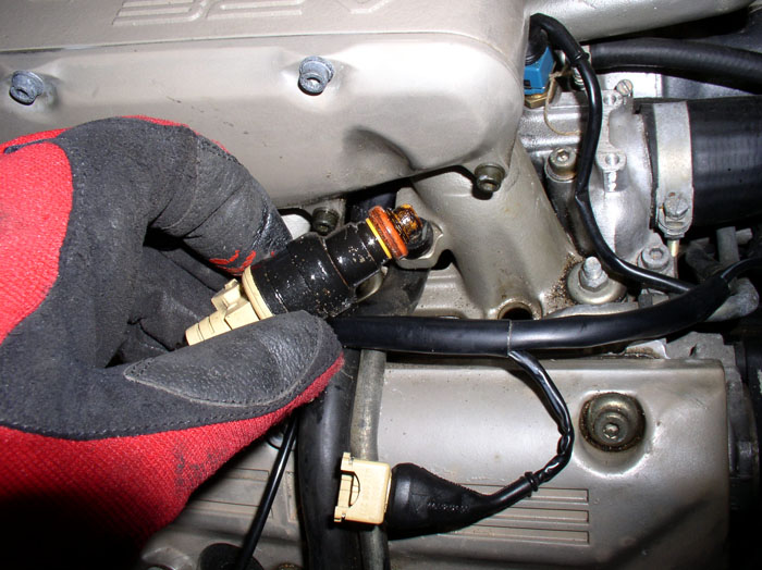
Inspect the injectors as you pull them out. Mine were covered in gunk at the pintle cap but the pintle end seemed to be fine.
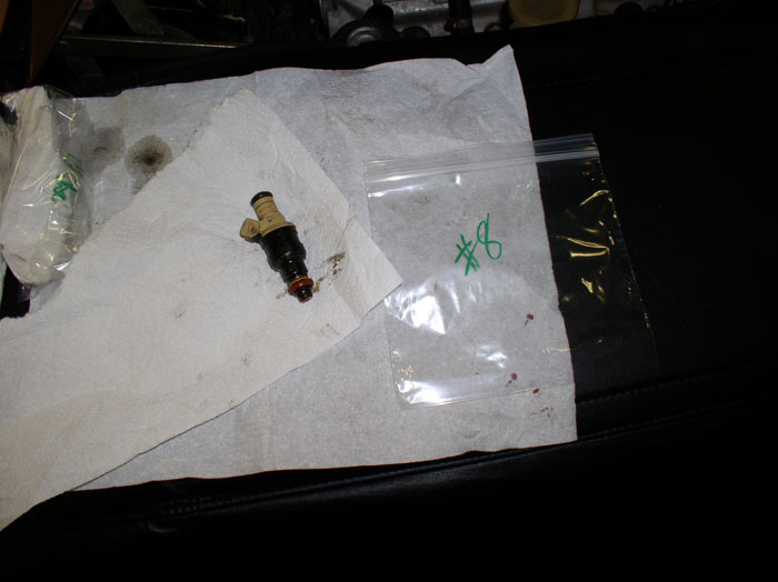
I decided to send the injectors off to Witchhunter for cleaning even though the PO had them cleaned back in 2002. Either way, bag and number the injectors. I prefer to number the injectors so I can put them back in the same cylinder on the install.
Plug the FI holes after removing the injectors to prevent debris from entering the head. I used strips of paper towel.
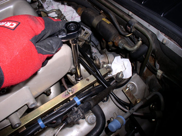
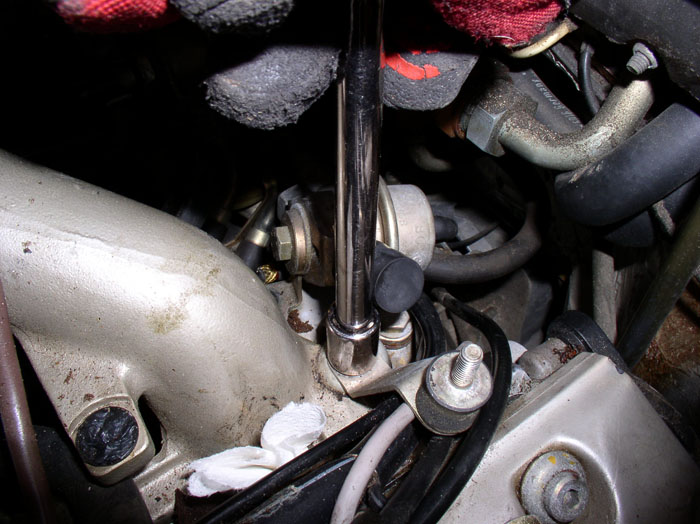
Next, remove the rear fuel pressure damper and fuel pressure regulator mounting bolts and nuts. These are 13mm bolts and nuts. One bolt and one nut for each fuel device. First the bolt that holds the damper bracket to the rear coolant port.
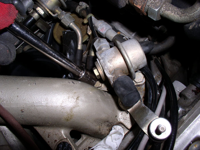
The damper nut is next and holds the damper bracket to the intake mounting stud. The nut is a locking (tension) nut.
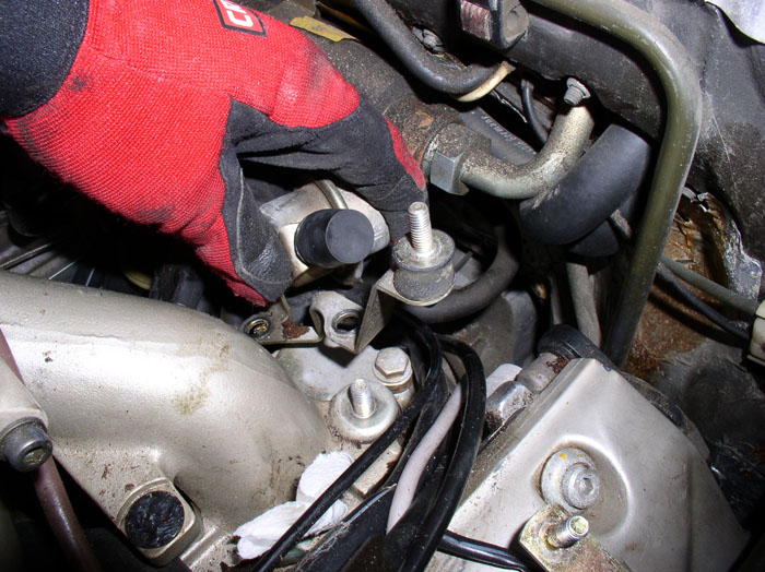
Do the same for the fuel pressure regulator on the passenger side. Then move the assembly out of the way - toward the firewall.
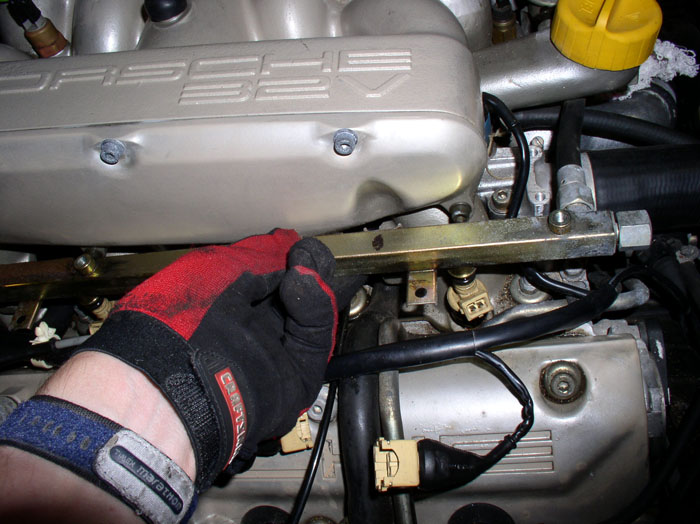
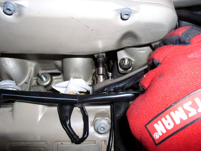
Next, begin removing the intake mounting nuts. There are 10 total, 5 on each side. They are 13mm locking (tension) nuts. You already removed one when you liberated the fuel pressure regulator and damper brackets. Only 8 to go. On the driver's side, use the socket extension (6") and universal elbow to get at the nuts under the cable mounting bracket.
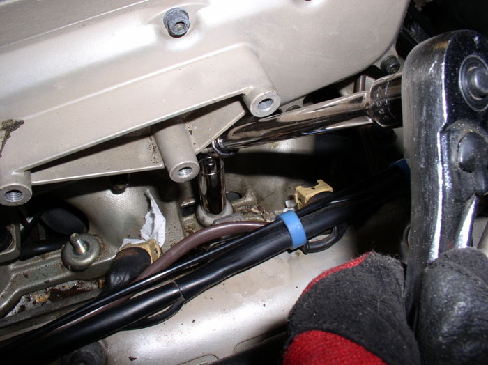
On the passenger side, one of the intake mounting nuts will require you to remove one of the allen head bolts to the side cover plate. It interferes with getting the socket on the 13mm nut. Remove the side cover plate allen head bolt with a 5mm allen head socket.
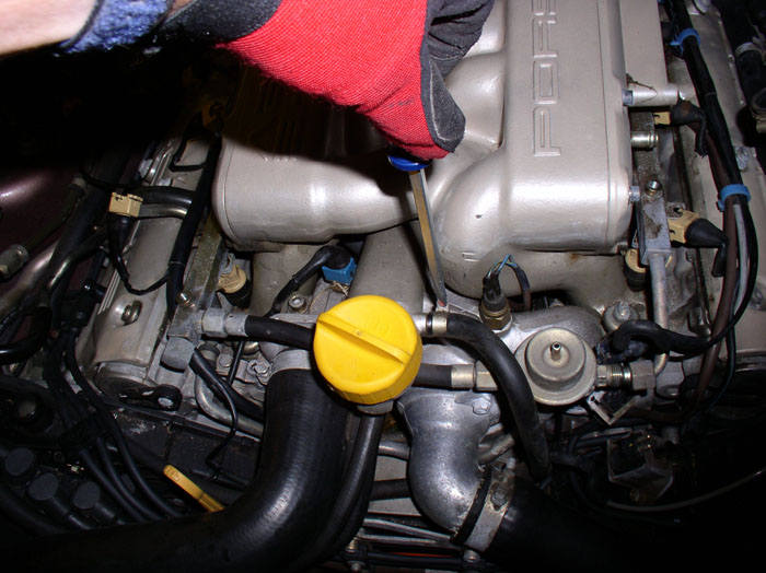
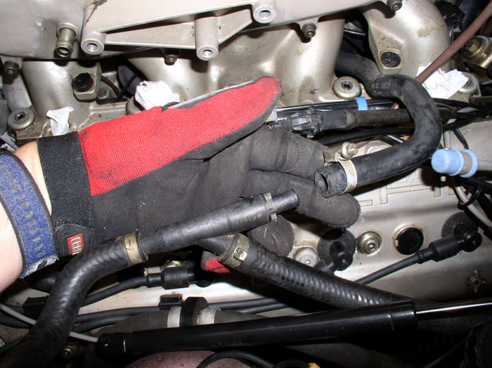
Using a screwdriver, loosen the hose clamps on the two PCV hoses at the passenger side cam covers and remove the hoses from the cam cover elbows.
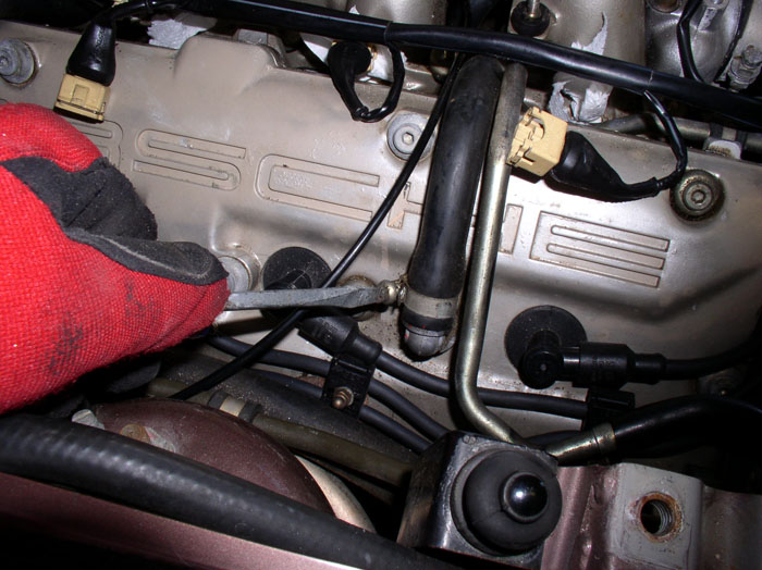
Re-route both of the PCV hoses so they are on top of the wiring harness.
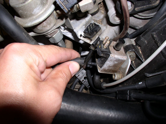
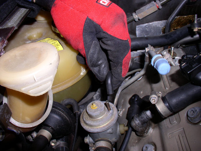
Disconnect the vacuum line elbow from the air pump diverter valve.
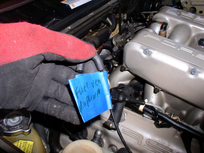
Disconnect the vacuum line elbow from the fuel tank vent diaphram that resides next to the coolant reservior. Label at least one of the hoses in order to keep them from getting mixed up on the install. If not, you can always follow the vacuum hose routing diagram to ensure the lines are connected correctly.
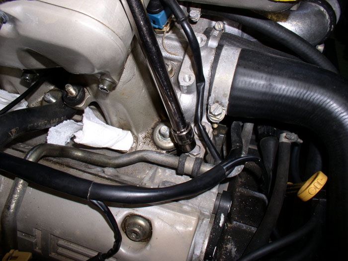
Loosen and remove the fuel inlet line clamp bolt. Use a 10mm socket with extension. This clamp needs to be removed in order for the front intake runner to clear the fuel line on removal.
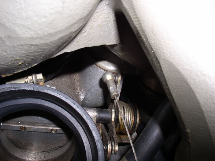
Disconnect the throttle plate cable by pulling or prying the ball connector at the end of the cable toward the throttle body.
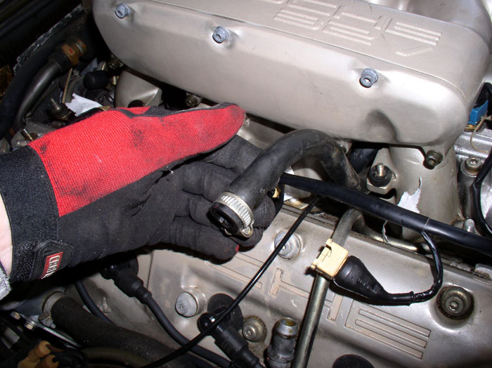
Loosen the clamp and disconnect the hose at the brake booster venturi that leads to the air guide cowl. Route the disconnected hose from the cowl so it's on top of the wiring harness.
continued......tomorrow......
I decided to send the injectors off to Witchhunter for cleaning even though the PO had them cleaned back in 2002. Either way, bag and number the injectors. I prefer to number the injectors so I can put them back in the same cylinder on the install.
Plug the FI holes after removing the injectors to prevent debris from entering the head. I used strips of paper towel.
Next, remove the rear fuel pressure damper and fuel pressure regulator mounting bolts and nuts. These are 13mm bolts and nuts. One bolt and one nut for each fuel device. First the bolt that holds the damper bracket to the rear coolant port.
The damper nut is next and holds the damper bracket to the intake mounting stud. The nut is a locking (tension) nut.
Do the same for the fuel pressure regulator on the passenger side. Then move the assembly out of the way - toward the firewall.
Next, begin removing the intake mounting nuts. There are 10 total, 5 on each side. They are 13mm locking (tension) nuts. You already removed one when you liberated the fuel pressure regulator and damper brackets. Only 8 to go. On the driver's side, use the socket extension (6") and universal elbow to get at the nuts under the cable mounting bracket.
On the passenger side, one of the intake mounting nuts will require you to remove one of the allen head bolts to the side cover plate. It interferes with getting the socket on the 13mm nut. Remove the side cover plate allen head bolt with a 5mm allen head socket.
Using a screwdriver, loosen the hose clamps on the two PCV hoses at the passenger side cam covers and remove the hoses from the cam cover elbows.
Re-route both of the PCV hoses so they are on top of the wiring harness.
Disconnect the vacuum line elbow from the air pump diverter valve.
Disconnect the vacuum line elbow from the fuel tank vent diaphram that resides next to the coolant reservior. Label at least one of the hoses in order to keep them from getting mixed up on the install. If not, you can always follow the vacuum hose routing diagram to ensure the lines are connected correctly.
Loosen and remove the fuel inlet line clamp bolt. Use a 10mm socket with extension. This clamp needs to be removed in order for the front intake runner to clear the fuel line on removal.
Disconnect the throttle plate cable by pulling or prying the ball connector at the end of the cable toward the throttle body.
Loosen the clamp and disconnect the hose at the brake booster venturi that leads to the air guide cowl. Route the disconnected hose from the cowl so it's on top of the wiring harness.
continued......tomorrow......
01-17-2009, 03:03 AM
#13
Rennlist Member
Thread Starter
Join Date: Sep 2007
Location: Ridgecrest, California
Posts: 1,363
Likes: 0
Received 143 Likes
on
28 Posts
Hello Tony,
THANKS!
Yes. It's in the section where they sell natual gas tools/supplies near furnace filters. It costs about $9.00. It's a great guage for low pressure (i.e., less than 10-20 psi) testing.
THANKS!
Yes. It's in the section where they sell natual gas tools/supplies near furnace filters. It costs about $9.00. It's a great guage for low pressure (i.e., less than 10-20 psi) testing.
01-17-2009, 03:08 AM
#14
Rennlist Member
Wow. Nice. Virginia's "before" looks better than our 86's "after". (Also Looking forward to that AC project write-up.)
Exceptional documentation. Thanks.
Exceptional documentation. Thanks.
01-17-2009, 03:19 AM
#15
Rennlist Member
Dwayne - once again an excellent tutorial - you are generating a layman's WSM, except more user friendly and thorough!
One counter-point view regarding the cross brace removal, however - I always remove it before lifting, per WSM standard, and I have never cracked a windshield. See, e.g., this thread: https://rennlist.com/forums/928-foru...oss-brace.html,
and reference WSM 10-2.
One counter-point view regarding the cross brace removal, however - I always remove it before lifting, per WSM standard, and I have never cracked a windshield. See, e.g., this thread: https://rennlist.com/forums/928-foru...oss-brace.html,
and reference WSM 10-2.

