When you click on links to various merchants on this site and make a purchase, this can result in this site earning a commission. Affiliate programs and affiliations include, but are not limited to, the eBay Partner Network.
5.0 to 5.3 corresponds to the last 20% of the 'window' and 4.5 is center of the window...
... on my Kempf tool which I've calibrated with my 9201.
I've measured two other Kempf tools and there was - IIRC - a 10% variance between the three.
On a good condition Kempf tool, that is uncalibrared against a 9201, I would set the belt at 90% which should be in the 5.0 to 5.3 range. (For a 32v engine.)
As I remember the instructions for the Kempf tool, there was no distinction between the 16V and 32V models.
This is correct. The pictures for the 32v in Kempf's manual were taken by me. This was also about 15 years ago. It was before I got really serious about working on other people's 928s, before I had a 9201 tool, and before I realized that the 16v tension was supposed to be lower than 32v since my experience at that time was maybe 3 or 4 t-belts all on 32v engines. I didn't question Jay's methodology at the time. (And yes, all those initial belt jobs ended up with about 4.5 - 4.7 tension - too low for a 32v.)
The instructions could use revision.
Regarding calibration I have no idea how you chaps with the 9201 tool calibrate it but hopefully you have something to calibrate it against
There's a calibration bar that comes with the tool.
Dave's comment shows he saw a value spread of 10% over 3 such gauges in whatever condition they might have been - it might be interesting to know how consistent the readings would be if the 9201 reads a given belt 3 times in succession. One expects them to be pretty much the same but...?
It takes a long time to calibrate one Kempf tool against the 9201. You have to do multiple measurements with each and rotate the engine twice between each measurement because a) the belt tension changes minutely with each measurement - more so with the Kempf than the 9201 and b) I find that you need a minimum of three 9201 measurements to determine the actual belt tension +/- 0.1 as the tool is just too sensitive to measurement technique.
Once you've determined the belt tension with ~5 9201 measurements then you can 'calibrate' one or more Kempf tools serially.
Thanks for sharing that info- good to know I am in the right ball park as it were. I remember communicating with Jay around the time he was developing his kit.
As a matter of interest, [and as per Greg's query] any idea where the notch should be when tightening the 16V models using this tool? Presumably somewhere in the lower end of the range I suspect.
As a matter of interest, [and as per Greg's query] any idea where the notch should be when tightening the 16V models using this tool? Presumably somewhere in the lower end of the range I suspect.
I figured Greg was asking about 32v lumps. Nonetheless, as per the above, on my Kempf 4.5 is the middle of the window and 4.5 is what the WSM says for a 16v.
I figured Greg was asking about 32v lumps. Nonetheless, as per the above, on my Kempf 4.5 is the middle of the window and 4.5 is what the WSM says for a 16v.
General interest, but yes, mostly for 32 valve engines, right now.
Looking at this tool, I figured that since it was designed for the 2 valve belts (4.5), the two different lines were the "window" for this belt.
I therefore assumed that the setting point for the 32 valve engines would be much higher on the scale.
A lot of people associate the acronym HTD with synchronous belts.
While there is good reason for this, most take it a little too far,
and believe that HTD refers to all synchronous belts.
This is not the case.
HTD stands for High Torque Drive, and calls out a specific tooth profile.
This type of profile is called a curvilinear profile.
An HTD tooth form looks like a half circle.
Other curvilinear profiles are available today as well, including our GT profile.
Alright. Listen up and listen good.
I am small potatoes on Rennlist. I am working with my first and only 928.
I respect the both of you and so far have had excellent dealings with both of you. I do understand there is considerable emnity between you.
However, do not get my thread locked!!! Take your bickering to PM's or such. I am just trying to figure out what has gone wrong with the belt tensioning system on my 32V 928 engine.
I have received alot of excellent advice and information, from you two as well.
Allow me to continue learning so I can put this thing back together and go from there.
Tonight, I got some more work done on the front of the engine in the Red Witch.
I found a few surprises:
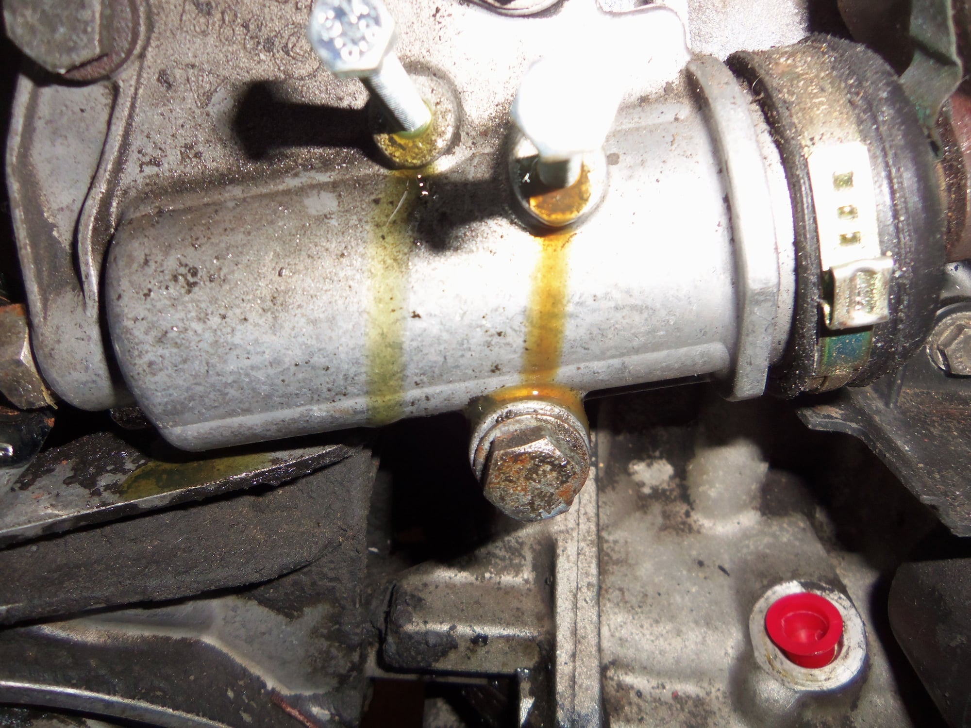
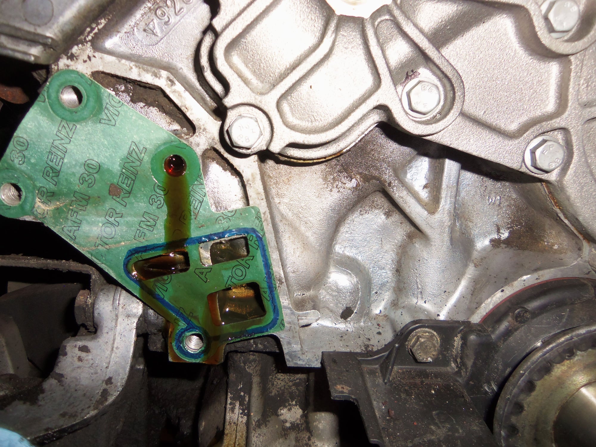
When I started backing off the tensioning screw on the back of the tensioner, oil started coming out of both of the ports on the body. Not sure what to make of that. So, Gary did fill the tensioner. No idea why the bleed/fill screws were dry, and why no oil came out when I removed them. After removing the tensioner from the block, I could see the back of the tensioner was full of oil, and there was, I believe, engine oil weeping from one of the bolt holes.
I will be cleaning all that up and fitting a new gasket with Hondabond 4.
As well, I will be disassembling the tensioner and having a look-see inside. I am assuming the boot clamp is a one-time-use thing?
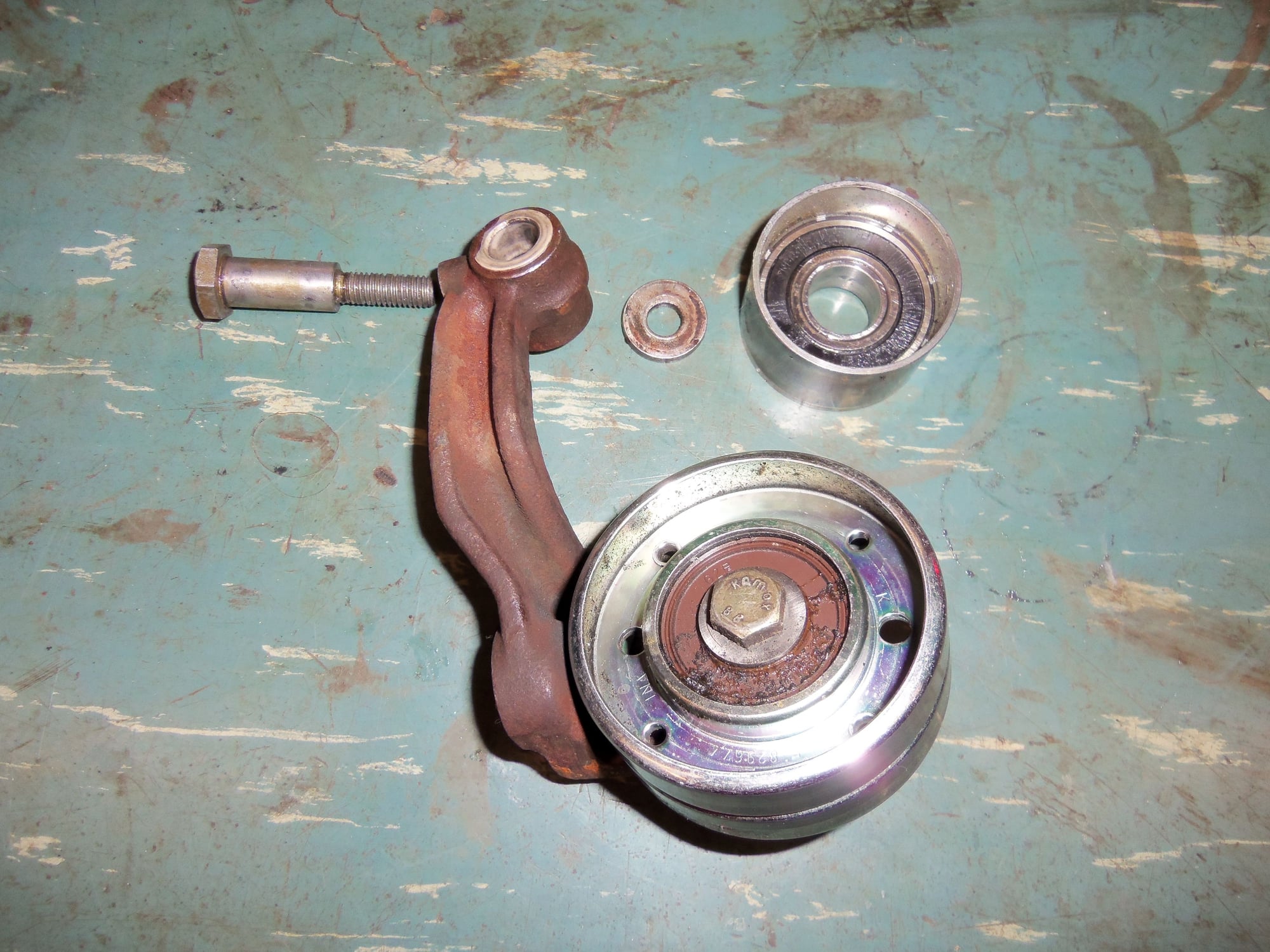
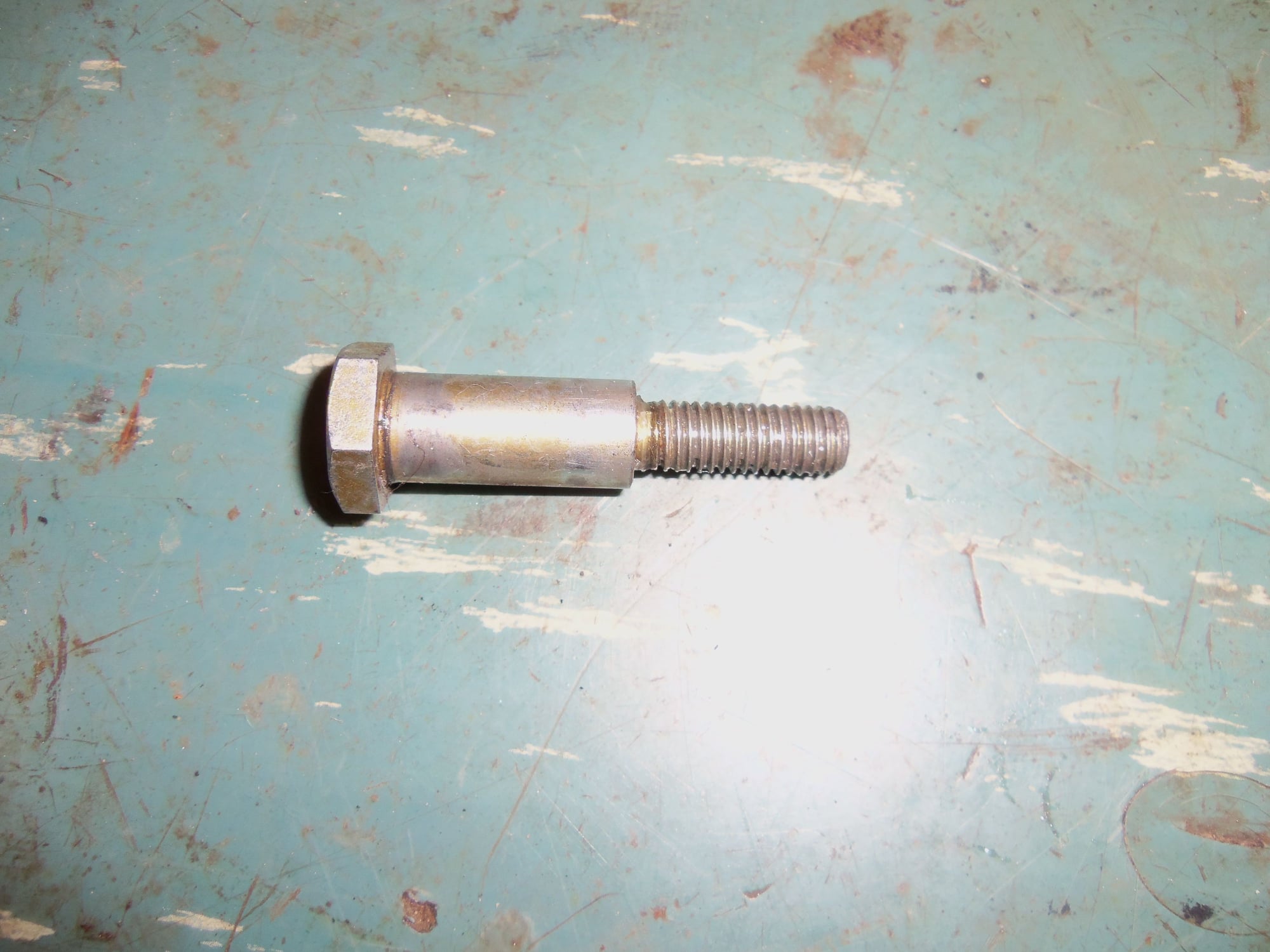
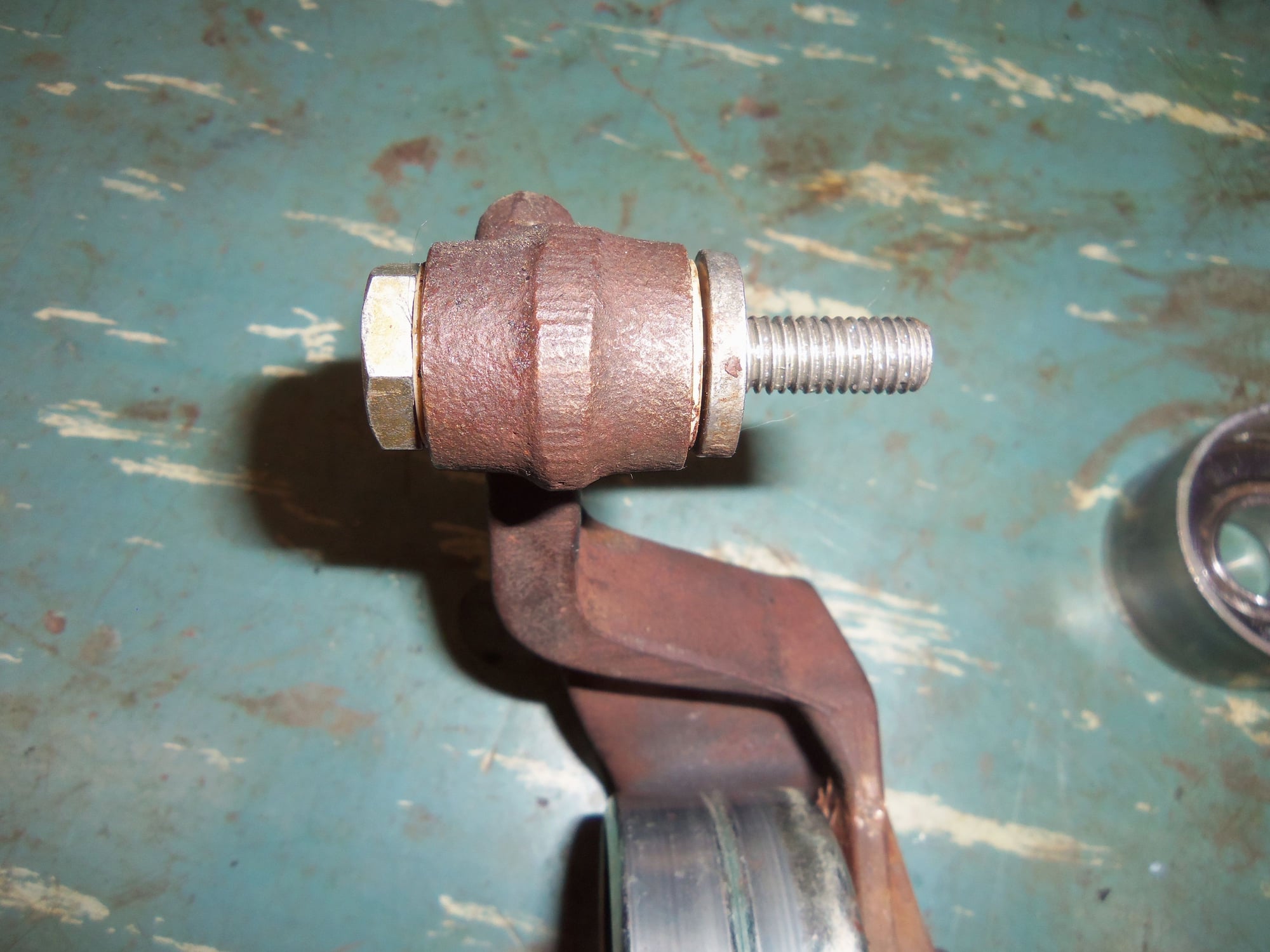
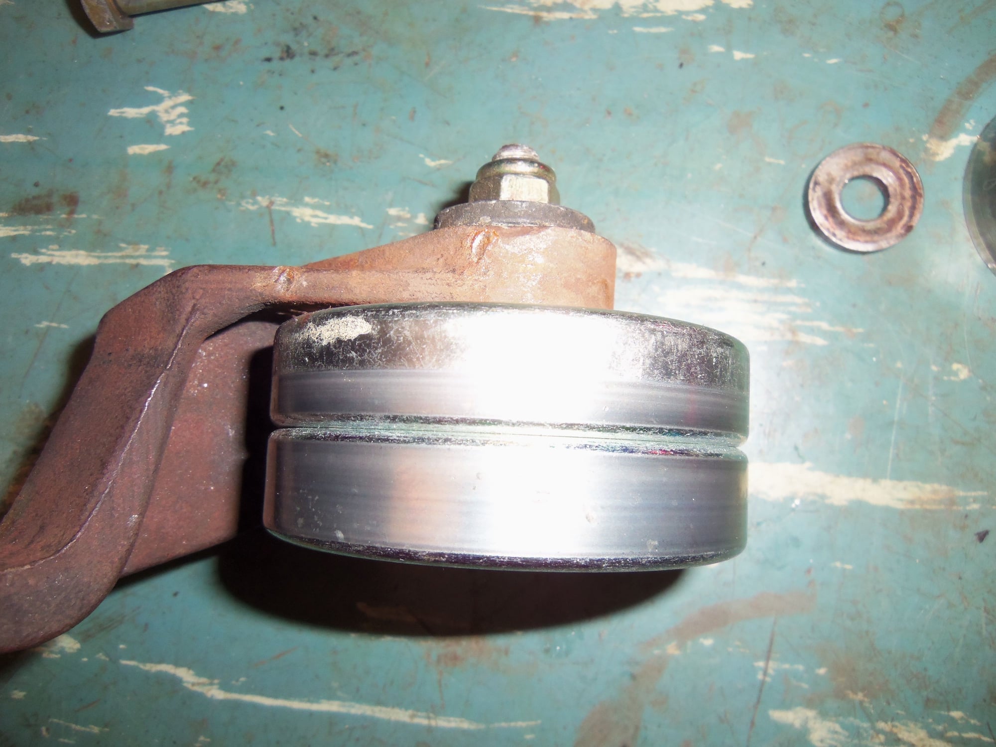
When I removed the tensioner roller lever bolt, it was not bent. I broke the bolt loose with a 6 point box end wrench, then turned it out with a thin section open end wrench so I could watch it. I did not see the bolt head or the tensioner roller lever wobble. With the roller lever removed, I put the bolt back through the bushings. The bolt was tight in the front bushing and quite tight in the rear bushing. When I turned the bolt, I did not see the threaded end wobble at all. I even held a small machinist's rule against the shoulder portion of the bolt and compared the gap on both sides to the threaded section. I could see no difference.
Should I buy a new tenioner bolt anyway?
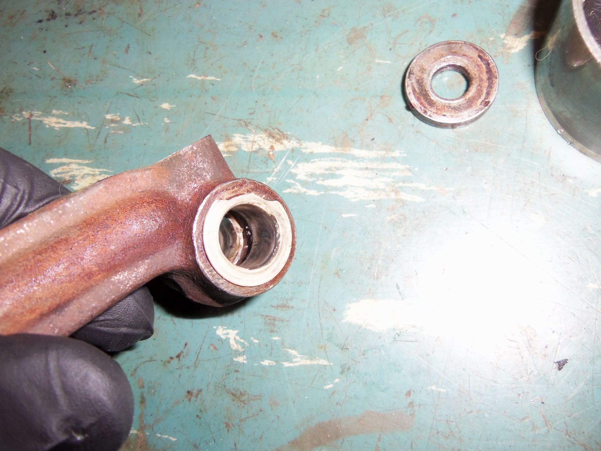
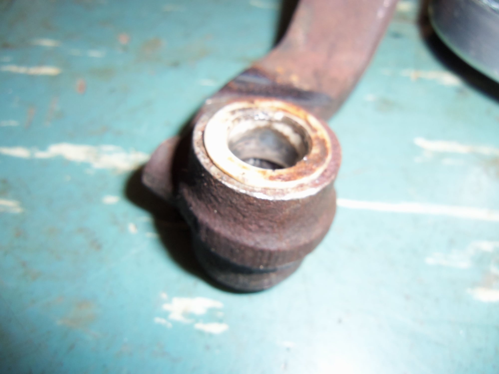
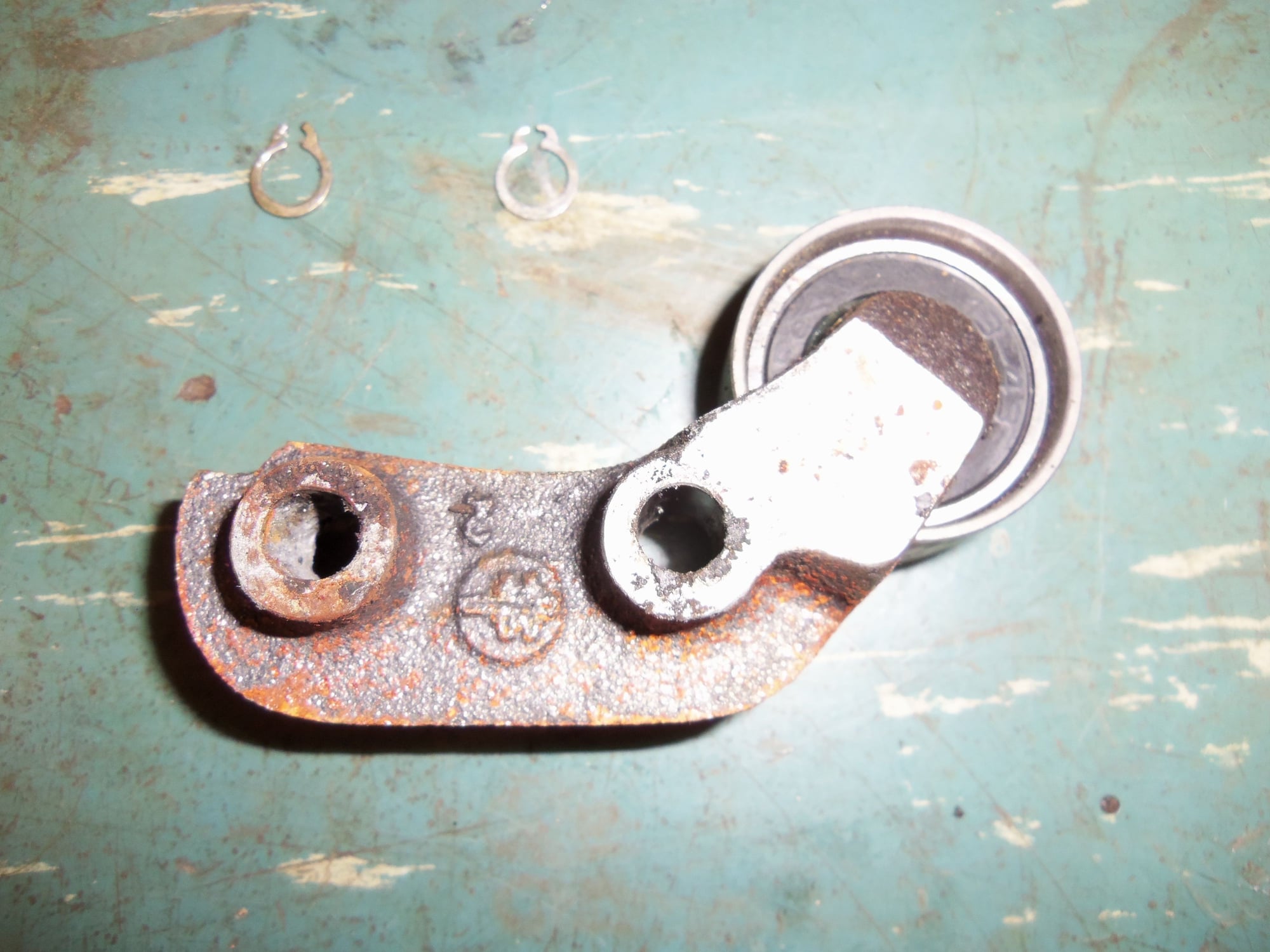
The bushings looked OK, though the front one has part of its lip broken off.
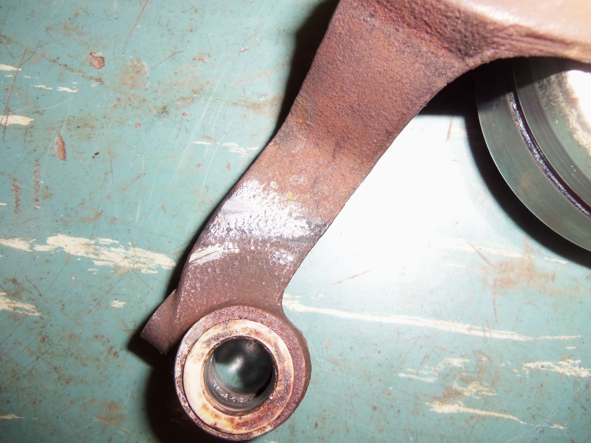
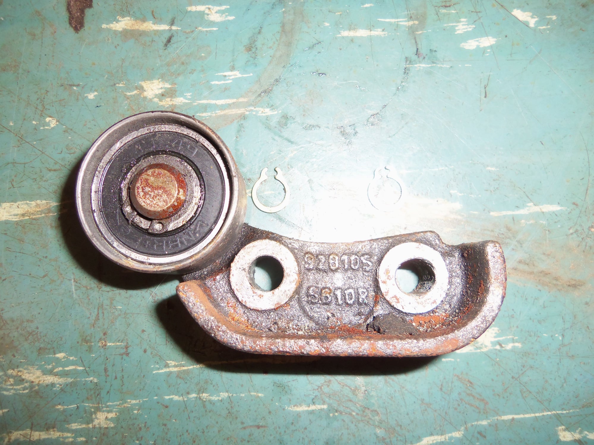
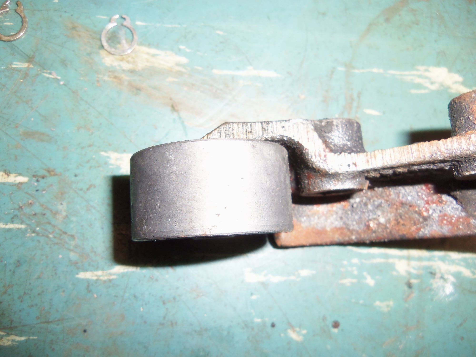
The rest of the roller lever components looked good. However, there was a noticeable wear pattern on both the lever roller and the roller that presses onto the water pump. Both show the belt riding forward on them.
As well, you can see where the belt was riding against the back of the roller lever. The belt shows a little wear on the front edge from riding on the roller lever. However, it looks more like burnishing than wear. I think it will be OK.
I did not get a picture of the edge of the belt, but I can if anyone wants to see it.
Wear from the belt rubbing against the back side of the roller lever.
Wear pattern showing the belt was riding at the front of the roller and off the edge.
I think this wear might be OK, being indicative of where the belt should ride. But, I'm not sure.
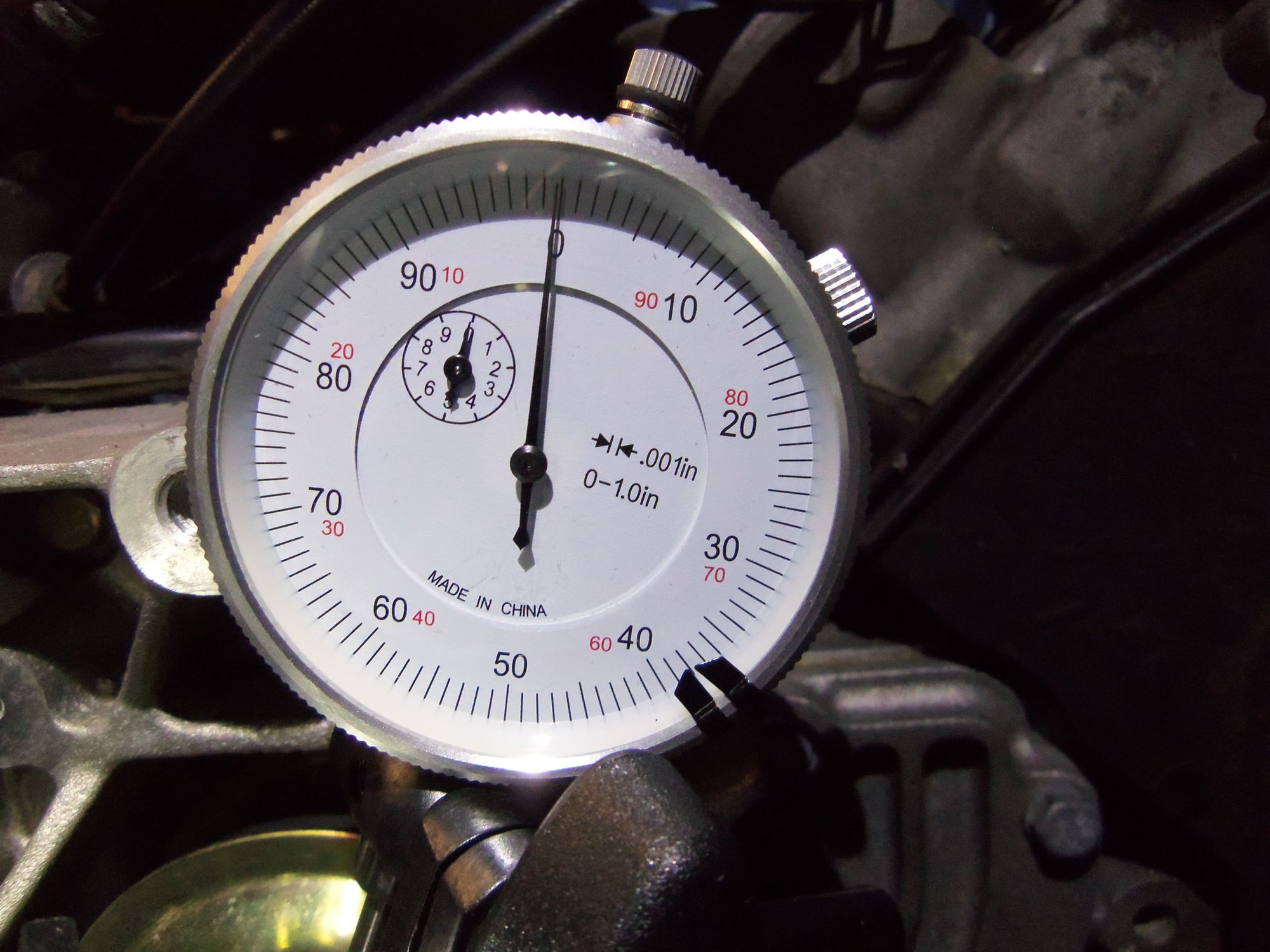
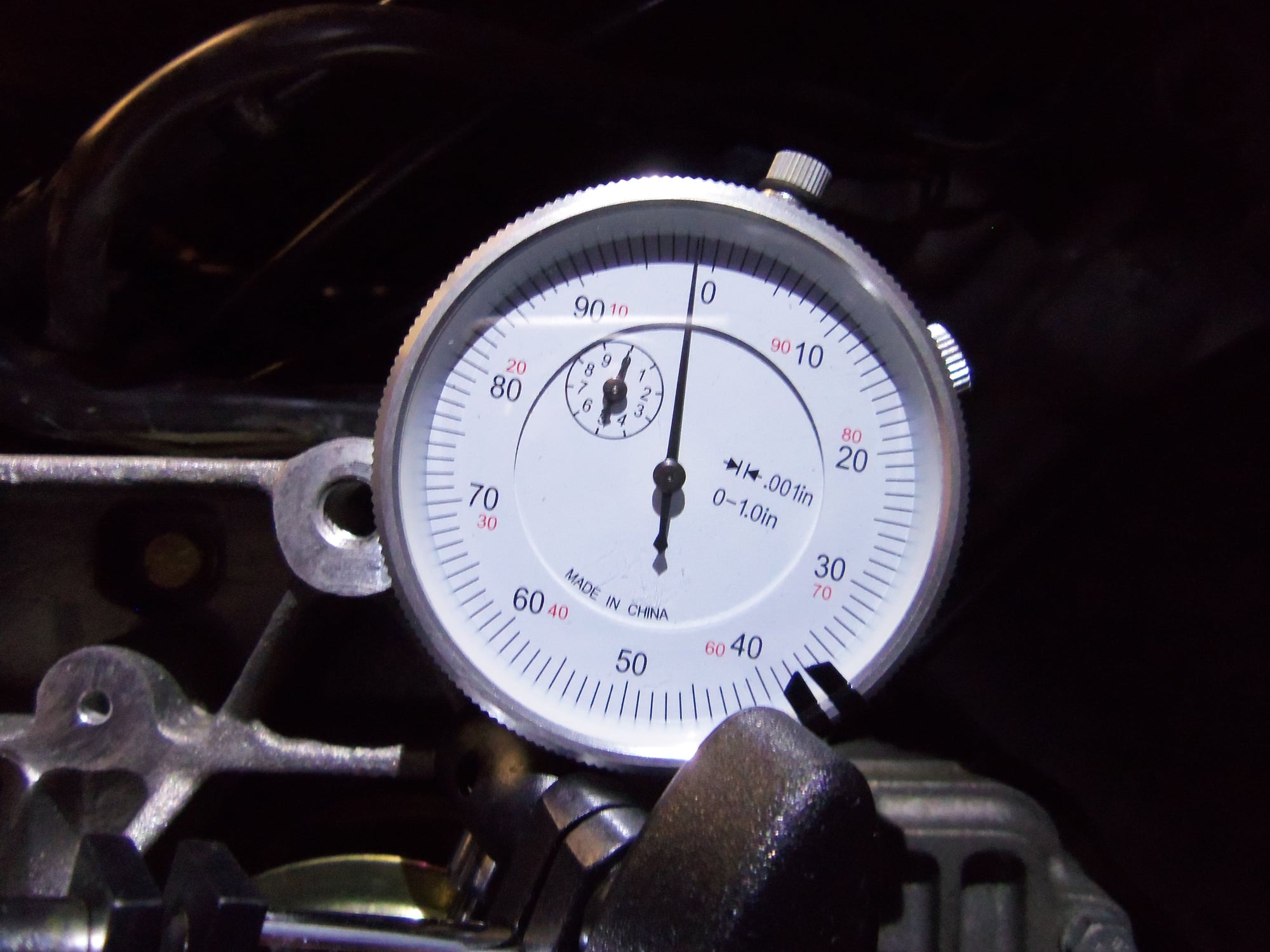
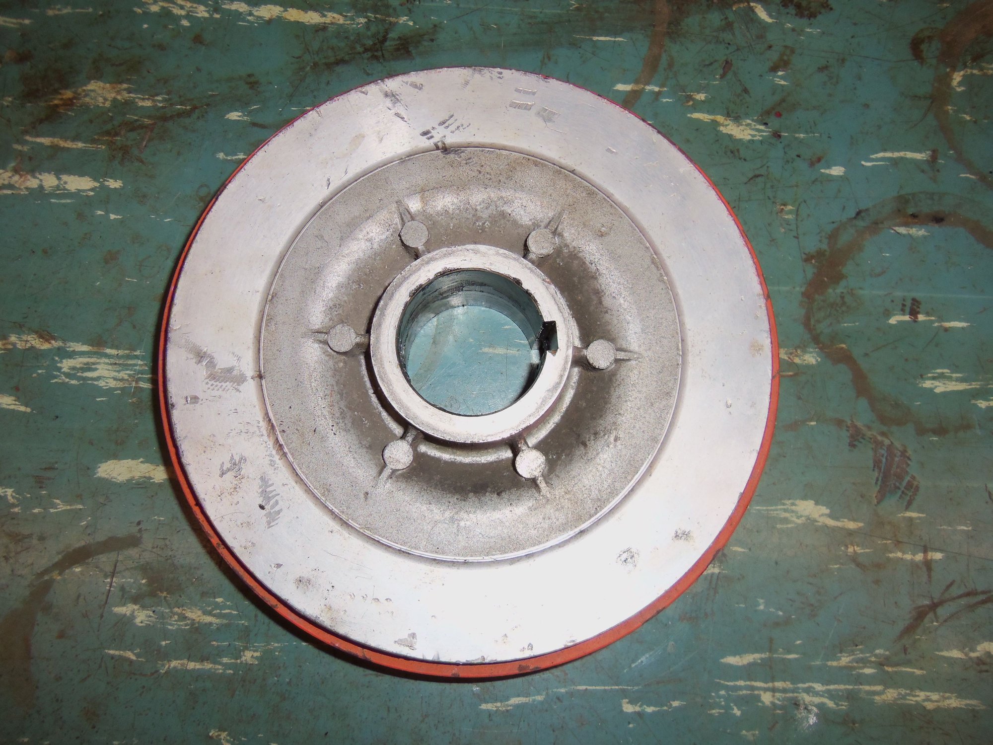
Biggest and most concerning surprise: There is approximately 0.003" radial play at the water pump pulley. I rotated the pulley, listening for any scraping or odd noises. I heard none. For giggles, I tried to move the pulley up and down to feel for any play. I felt play. Noticeable play. Not the pulley flopping around, but I could feel definite movement up and down.
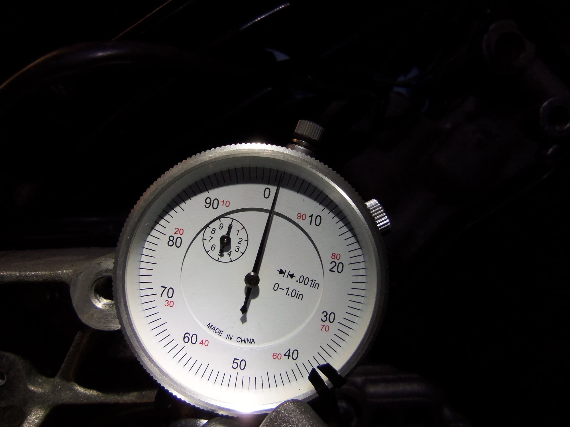
Trying to quantify this movement, I rigged up my dial indicator. For lack of a better idea, I set the magnetic base on the nose of the crankshaft. I worked better than I expected. Once I got the indicator rigged where it would read, I noted approximately 0.00175" play up and approximately 0.00125" play down, with the pulley centering with no pressure.
This really has me worried. This pump was new, and has only run for 2000 miles. Casting mark says its a Laso pump. Earlier in the teardown, I was able to see a sliver of the impeller through the water bridge hole in the block. Impeller looked plastic.
I have not yet removed the water pump.
Setup to read play in water pump pulley. Yes, I know my base and dial indicator are Chinese as h*ll. I am working with what I have...
Indicator was on true zero, I bumped it slightly taking the photo. I zero'd it back out before doing the check.
Approximately 0.00175" play up.
Approximately 0.00125" play down.
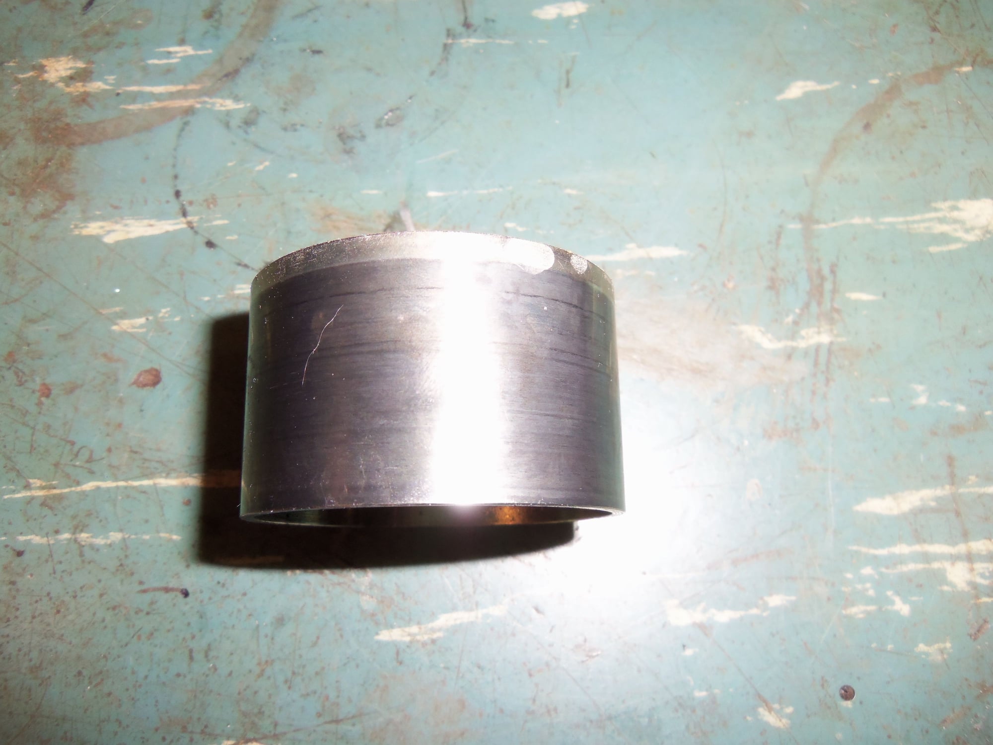
The lower roller assembly under the crankshaft looked good. The roller was new, and does not appear to have had the belt rub against it yet. The bracket was a tight fit on its mounting pins. Only anamoly I found is the little washers were not under the tiny snap rings that hold the bracket on the posts. I will order new washers.
No wear on the roller. I don't believe the belt has ever touched it.
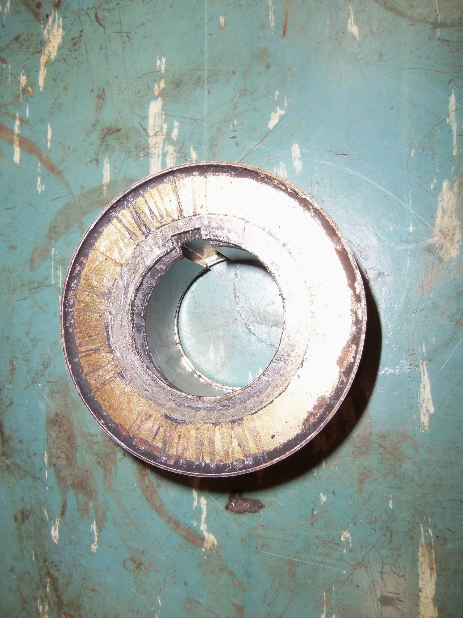
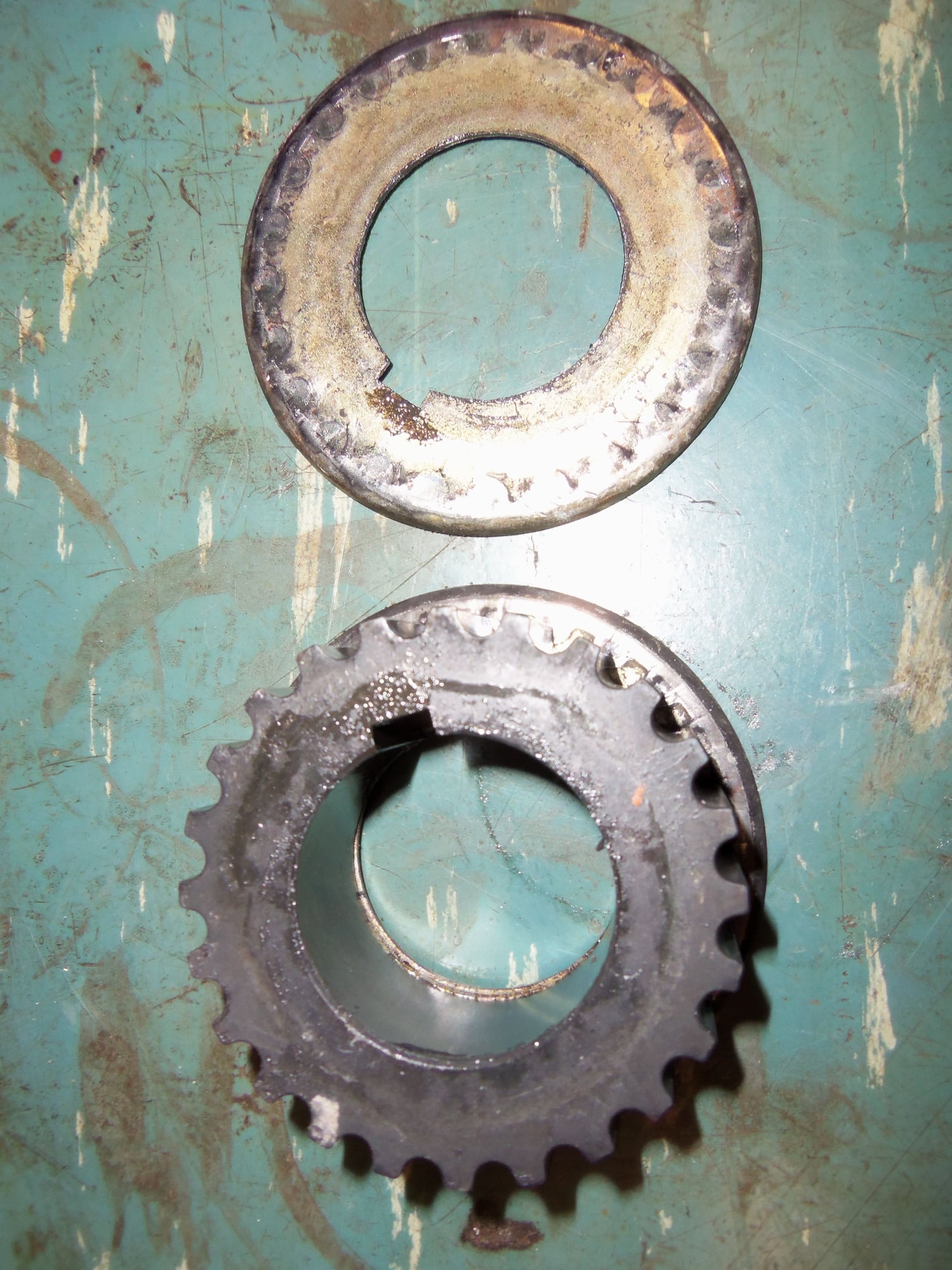
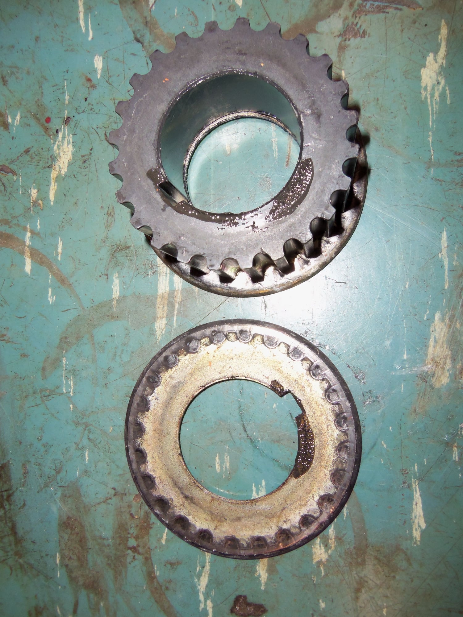
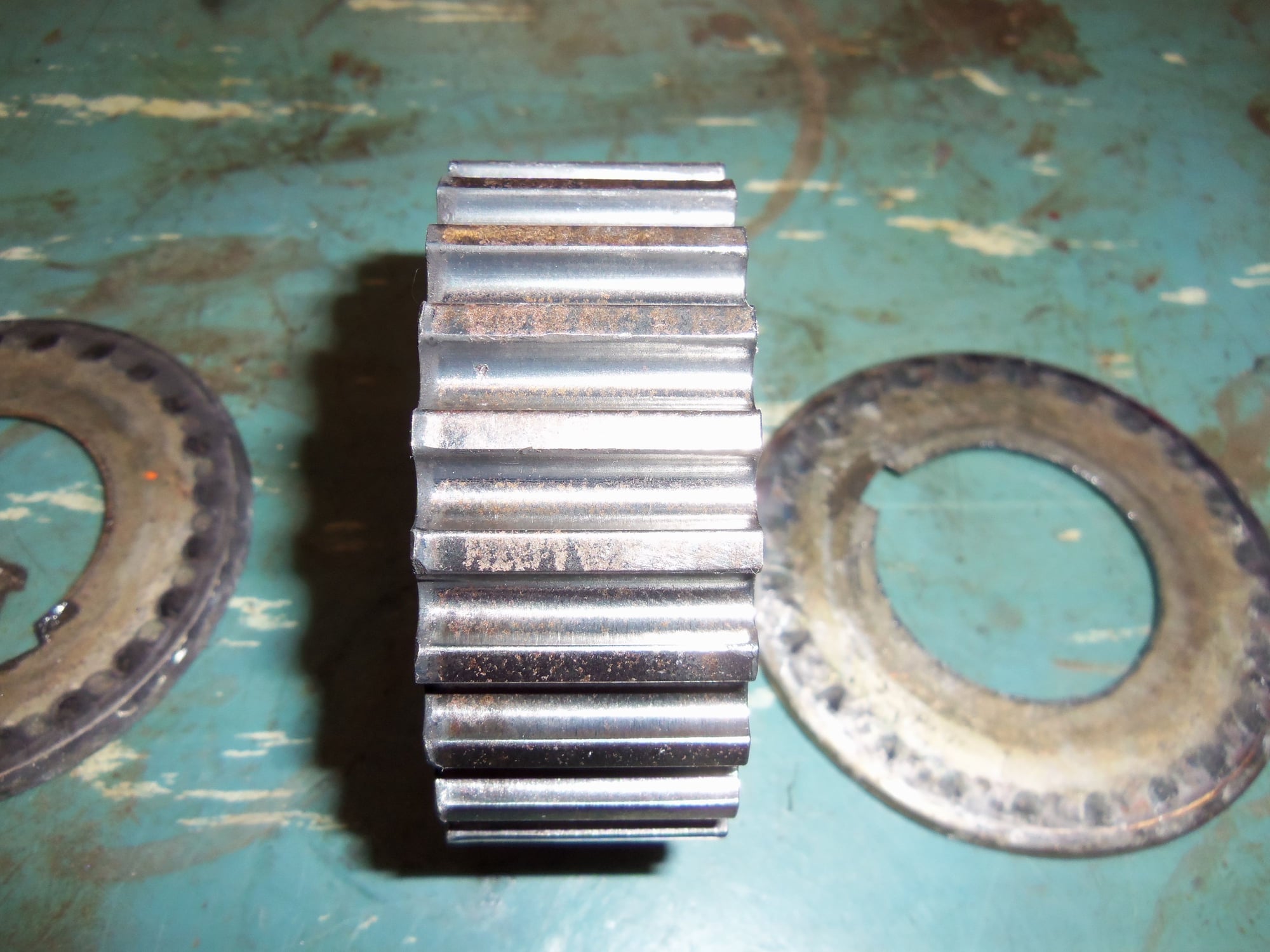
The crank gear and thrust washers show no odd wear, at least to my eyes. The crank gear was snug on the crank. I was able to pull it off by hand, but it took a little effort. I felt no wobble or radial play. Out of paranoia, I have zip-tied the front and rear thrust washers to the crank gear on their respective sides. I am going to keep track of it so I don't inadvertently put the crank gear on backwards.
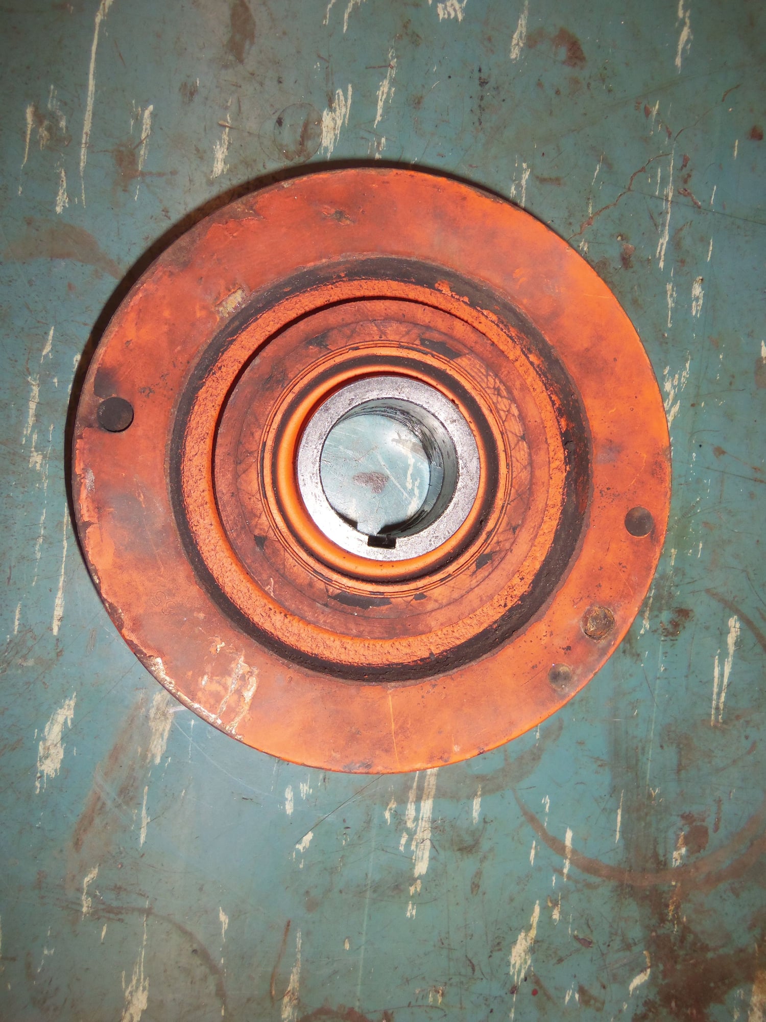
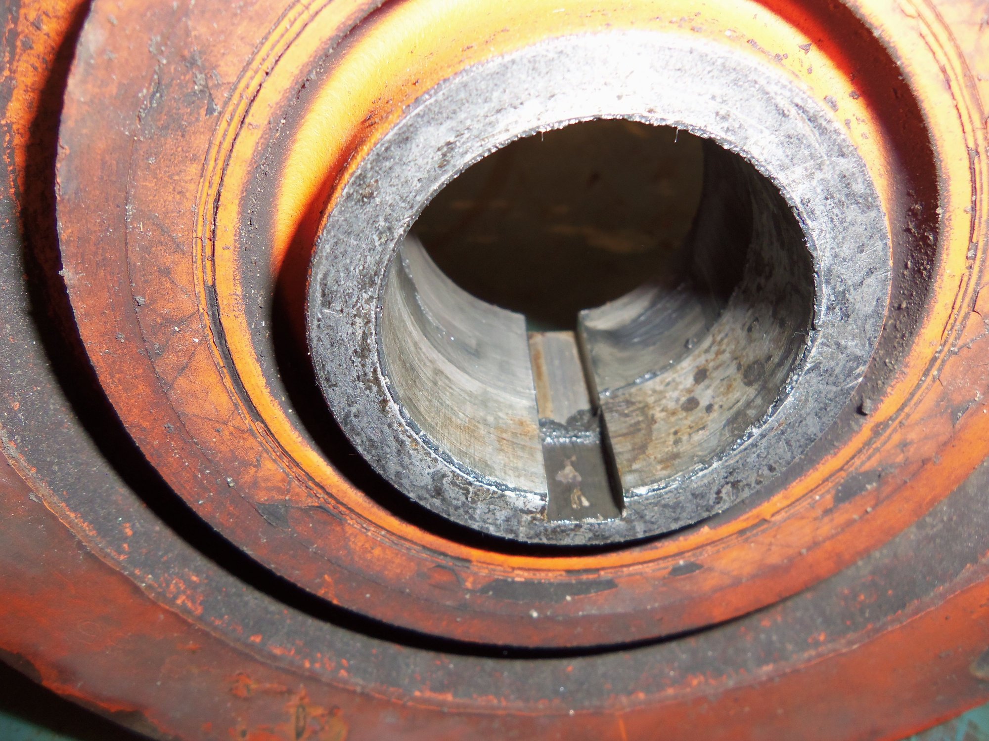
I will be glad when Greg Brown's ATI Superdamper arrives. The harmonic balancer came off by hand with no problem. I felt a touch of wobble pulling if off. Looking at the inside of the crank bore, I could see that it has not been tight on the crank. That makes rebuilding this balancer not a good idea.
This was not tight on the crank.
On a side note, removal of the tensioner from the engine gave me clearance to finish removing the air pump. It makes ungood noises when I spin it by hand. I have new bearings to put in it. However, I am leaning towards just leaving the air pump off.
Thought about what I am seeing: Since the bolt wasn't bent, and I found nothing else obviously wrong, could it just be that the tensioner roller lever needs to be spaced out a bit more? I don't know...
I am facing a very similar problem with my 79 after a fresh TB job. My pivot bolt shows no sign of being bent either once removed. I am replacing it anyway as good measure. Replacing arm too with another used unit just to be sure.

 02-12-2017, 11:02 AM