When you click on links to various merchants on this site and make a purchase, this can result in this site earning a commission. Affiliate programs and affiliations include, but are not limited to, the eBay Partner Network.
Yes I have. The oil pan is coming off for cleaning and installation of a silicone gasket and studs. The sump will be inspected for debris.
All eight rod caps will come off and all sixteen rod bearing shells will be inspected.
Yes I have. The oil pan is coming off for cleaning and installation of a silicone gasket and studs. The sump will be inspected for debris.
All eight rod caps will come off and all sixteen rod bearing shells will be inspected.
And I will go from there.
Plese keep the thread going as you take the pan off. Looks as though I may have to do the same thing in the not too distant future as I have a slowly leaking gasket.
The stud kit is nice. It makes installing the pan really simple. No "try to hold it in place and start bolts" hassle.
What I was told is to blue loctite the studs in (especially the ones that go into holes that are open at the top). And to measure the ones that go into blind holes and match up the ones in open holes.
DO NOT overtighten the bolts. The torque for the silicon gasket is insanely low. But if you overtorque it, the gasket will split and you will develop major oil leaks. You will then be doing it again.
Spec is 20-25 INCH pounds. I played around with my small torque wrench (Craftsman 3/8 drive, 25 - 250 in/lbs) and found I could get the correct torque using a screwdriver handle with a 1/4 in drive 10mm socket on it. I could get to about 40 in/lbs that way, so I got it "mostly tight".
Dwayne's writeup on the Motor mounts will get you most of the way to the pan. Starter, clutch slave, PS pump/Alternator, oil return tube & oil filter have to come out to get to the pan. Tedious, but nothing super difficult. Roger now has new boots for the oil level sensor, the old one is likely toast (literally - cooked to the point of disintegration).
One thing - putting the oil return tube and PS/Alt back on is a bit of a puzzle. Put the tube (and gasket) in, but don't install the bolts. Install the PS/Alt. Bolt the pipe in. You can't put the pipe in with the PS/Alt in, but you can't bolt up the PS/Alt with the pipe bolted down.
Thanks, Wisconisn Joe!
All of that dovetails with what I have learned. Biggest thing I have heard about the silicone oil pan gasket is just that, DON'T overtighten the bolts. It will ruin the gasket. I will be doing pretty much what have you have described.
As for the disassembly, I have most of that out of the way. Starter, AC compressor & bracket, Alt/PS & console are off. Engine will be jacked up soon and motor mounts removed.
Roger supplied a new oil level sender boot with the new harness that Sean Ratts fabricated for me. I am good there.
I am lucky in that the S3 32V does not have the oil return tube. Just a blank plate.
You bring up a good point. This is alot of work. However, if you break it up into pieces, it is manageable. None of it is too difficult.
Thanks!
Originally Posted by Ad0911
Subscribed to this thread. So much valuable info here.
Thank you, sir!
I am trying to document what I am doing and be useful to others trying to do the same thing.
Originally Posted by buccicone
Great pics, Seth. Now you know it has been done right. Concours clean!!
Thanks, Mike!
That means something to me. I know what has been done and I know I did it right. I don't think it is quite concours, but it is better than it was!
Originally Posted by Imo000
The silicone pan gasket needs crush rings. This would eliminate guessing when trying to tighten the bolt/nuts.
Originally Posted by Guy
Amen to that. Some ribbing may not be a bad idea either.
If I remember reading correctly, Jim Corenman tried to do just that. He found the gasket was not a consistent thickness throughout. His spacers were for naught.
I agree on the ribbing. However, it is what it is and I'm glad to have it.
OK, I spent some time today on the Red Witch tensioning the TB and checking cam timing.
Even though I am waiting on an ATI Superdamper from Greg Brown, I went ahead and torqued the balance and pulley stack on to 218 ft/lbs.
I walked belt tension up in several steps as opposed to one big hit. I would adjust the tensioner a bit, roll the engine over for one full revolution of the cams, then check tension. Repeat as necessary until the Kempf tool shows tension at the top of the window. It is my understanding from discussions on Rennlist that this setting is appropriate for 32V engines.
I rolled the engine over two more full revolutions of the cams and checked tension again. It was the same.
Oh, and I did check belt tension at the correct TDC this time...
Using the 32'Vr tool, I checked cam timing. Suprisingly, I was not off a tooth on the passenger's side sprocket like I thought I was. Ended up seeing the following:
Driver's side cam: 1� advanced
Passenger's side: 2� advanced
So, it has gotten a smidge better, as the driver's side cam was 2� advanced. Specs call for cam to be at 0�.
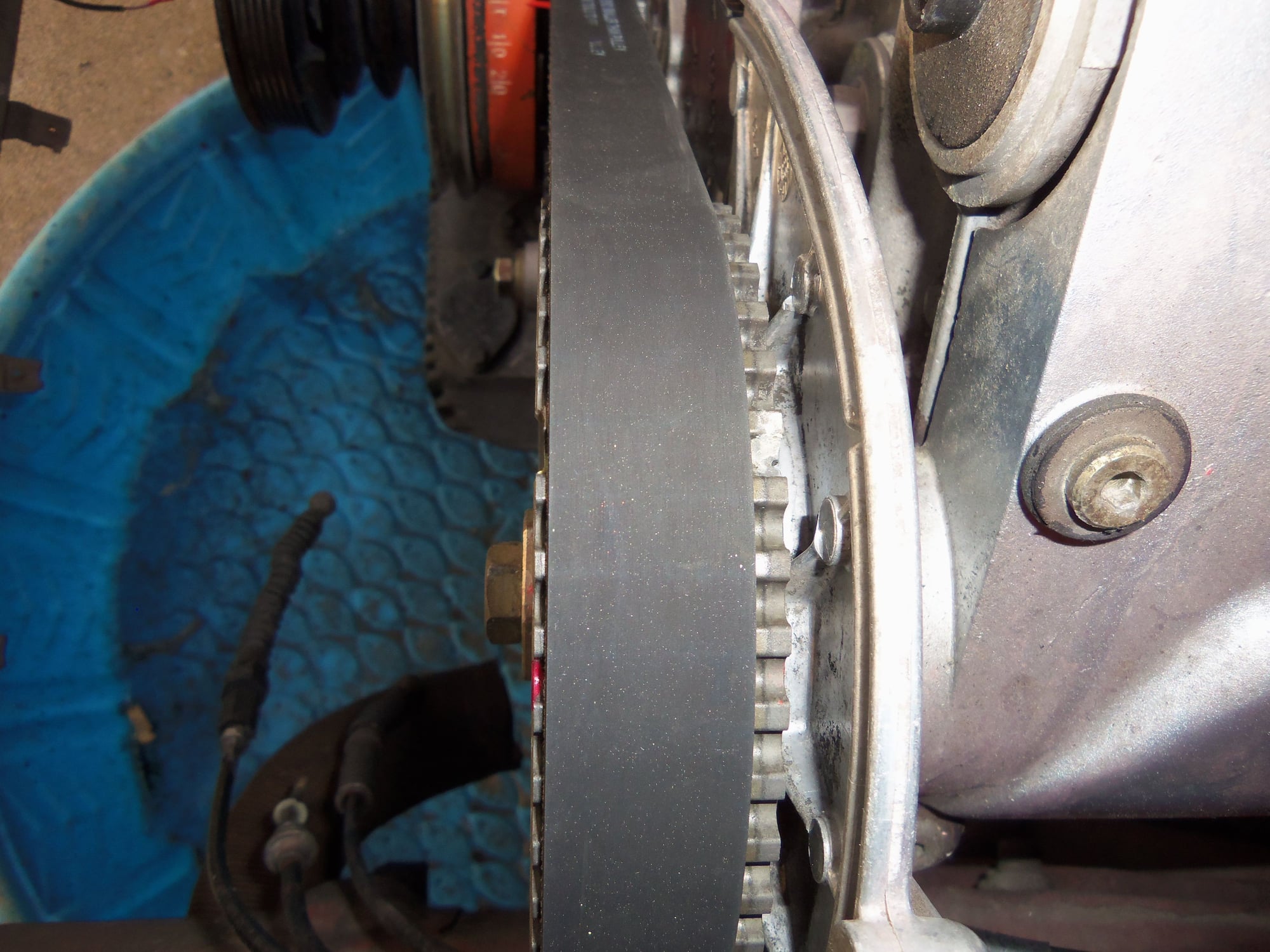
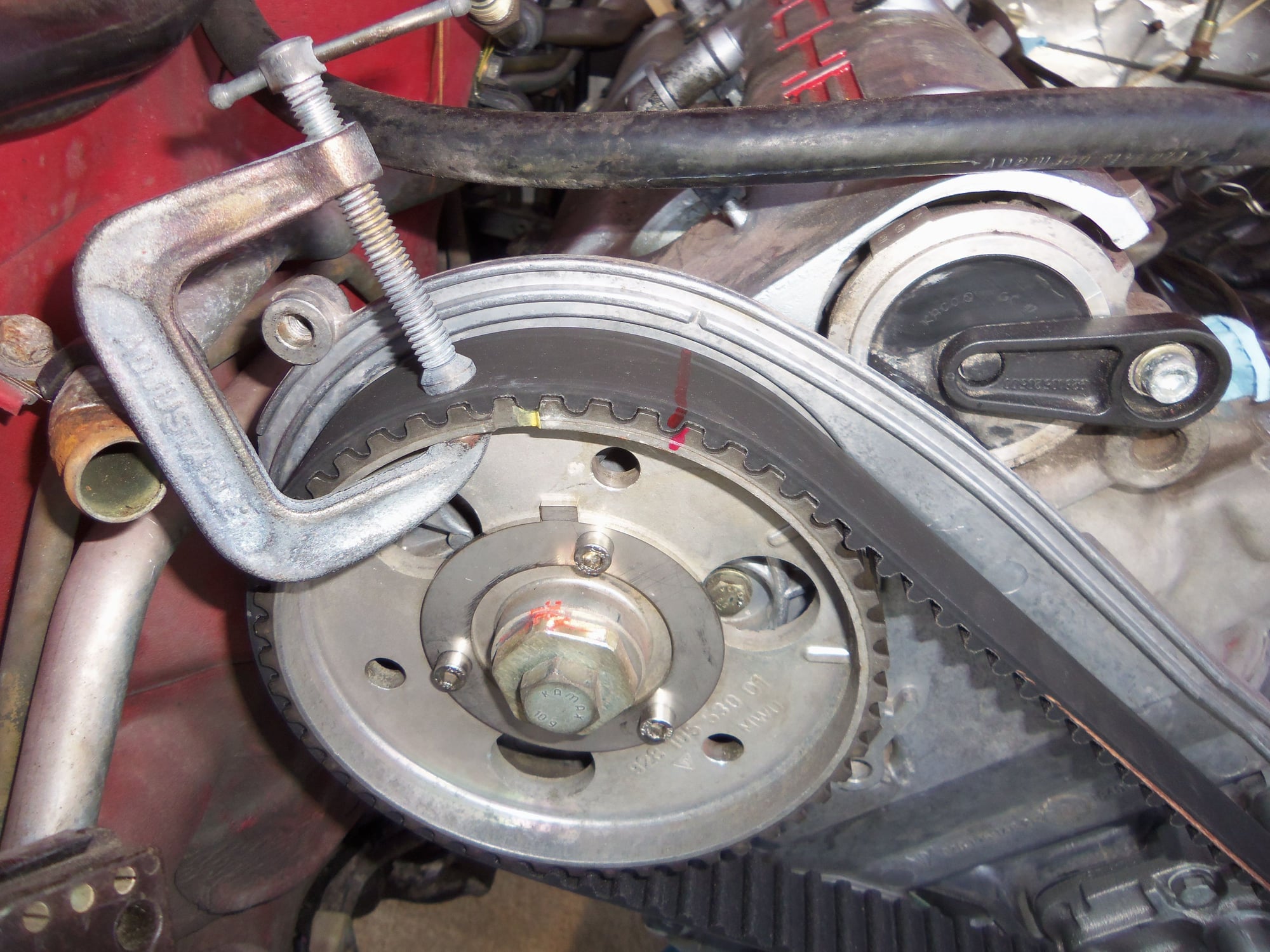
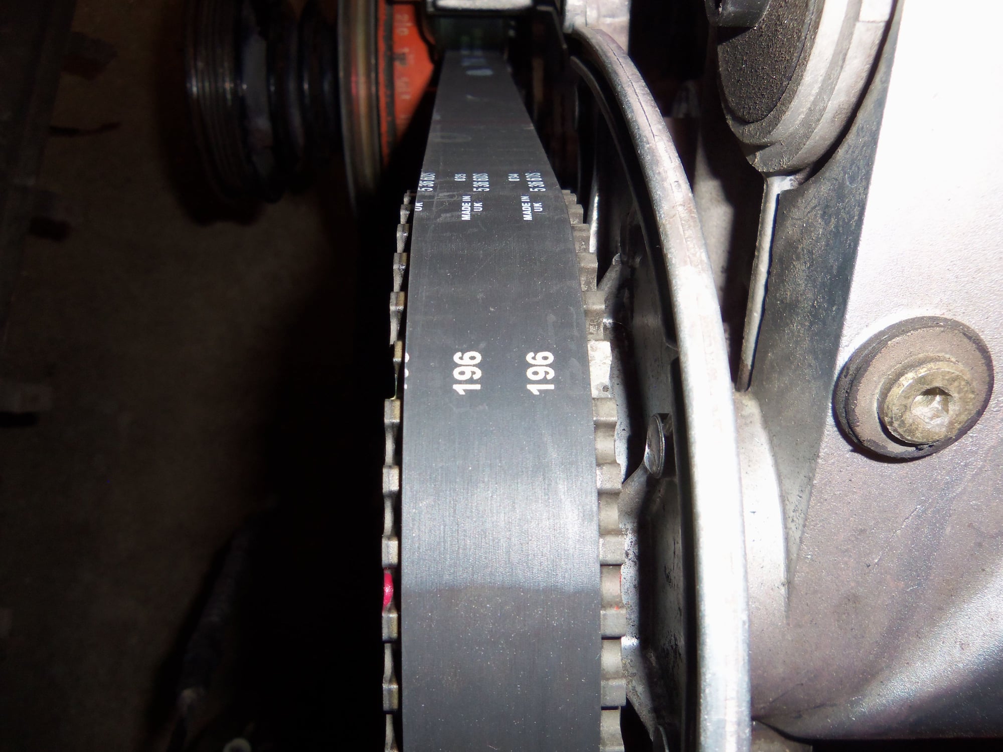
Now, something is STILL not right. The timing belt is tracking very far on the fronts of the cam sprockets. The driver's side sprocket only has approximately 1.6mm from the edge of the sprocket to the edge of the belt.
For giggles, I completely backed off the tensioner. And then wet my pants as I heard the belt go 'boing'. I thought it had jumped a tooth. I held the belt down on the leading edge of the driver's side sprocket as I slowly rolled the engine over to redistribute tension across the belt.
I pushed the timing belt as far back on the cam sprockets and the tensioner roller as I could with my fingers. I then started the process of walking belt tension back to the proper level. Even through this short amount of rolling the engine over, the belt started to track forward. Once the tension was set back to the top of the window, I rolled the engine over one full revolution of the cams. I verified cam timing was still correct.
Over the course of around six to eight full revolutions of the cams, the belt walked forward then stopped. I rolled the engine over another ten full revolutions of the cams. The belt never moved forward anymore. It stayed approximately 1.6mm from the edge of the driver's side sprocket.
The belt is riding a little bit off the edge of the tensioner roller, and appears to be riding towards the front lip of the water pump pulley.
I have no explanation for this. The water pump is new. The tensioner roller arm pivot bolt and bushings are new. The tensioner bushings were a light press fit into the tensioner roller arm. I carefully installed the arm so that it would not bind and bend the pivot bolt. The tensioner roller is not damaged and the bearing is fine.
Neither camshaft sprocket is wobbling as it turns. The oil pump sprocket is not damaged, and the pump turned smoothly by hand. It was new 2000 miles ago.
The crank sprocket is fine and has new thrust washers.
There is only one thing I saw, and I don't know what to do about it. When I installed the tensioner roller arm, I could feel the slightest amound of back and forth play between the arm and the pivot bolt. I am assuming that is the clearance between the new bushings and the new pivot bolt. The pivot bolt slid smoothly into the bushings in the arm, but did not feel loose.
When I put the belt all all the sprockets and rollers, the belt tension caused the tensioner roller arm to **** ever so slightly.
I don't know if that really matters, as it is on the return side, feeding into the passenger's side sprocket.
Note, the belt is not tracking as far forward on the passenger's side sprocket. I don't know what is causing the belt to run at the front lip of the water pump pulley and so far forward on the driver's side sprocket.
I read a few posts about timing belts that on some 928 engines, the belts just track towards the front of the sprockets.
Is this even a thing?
Tension is right at the top of the window on the Kempf tool.
Driver's side cam is 1� advanced.
Passenger's side cam is 2� retarded.
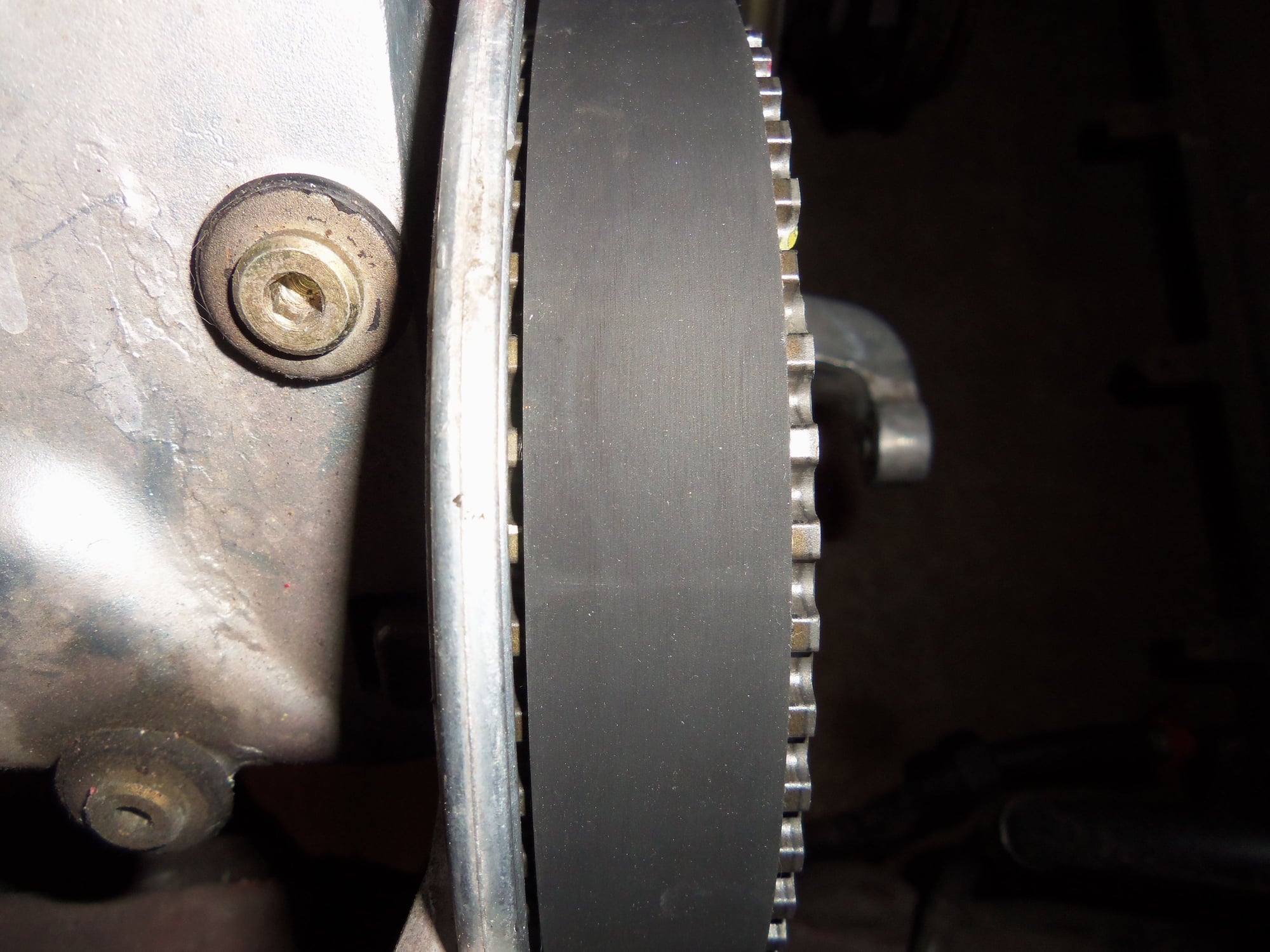
For reference: this is the tracking on the driver's side sprocket with the old belt and misaligned tensioner roller.
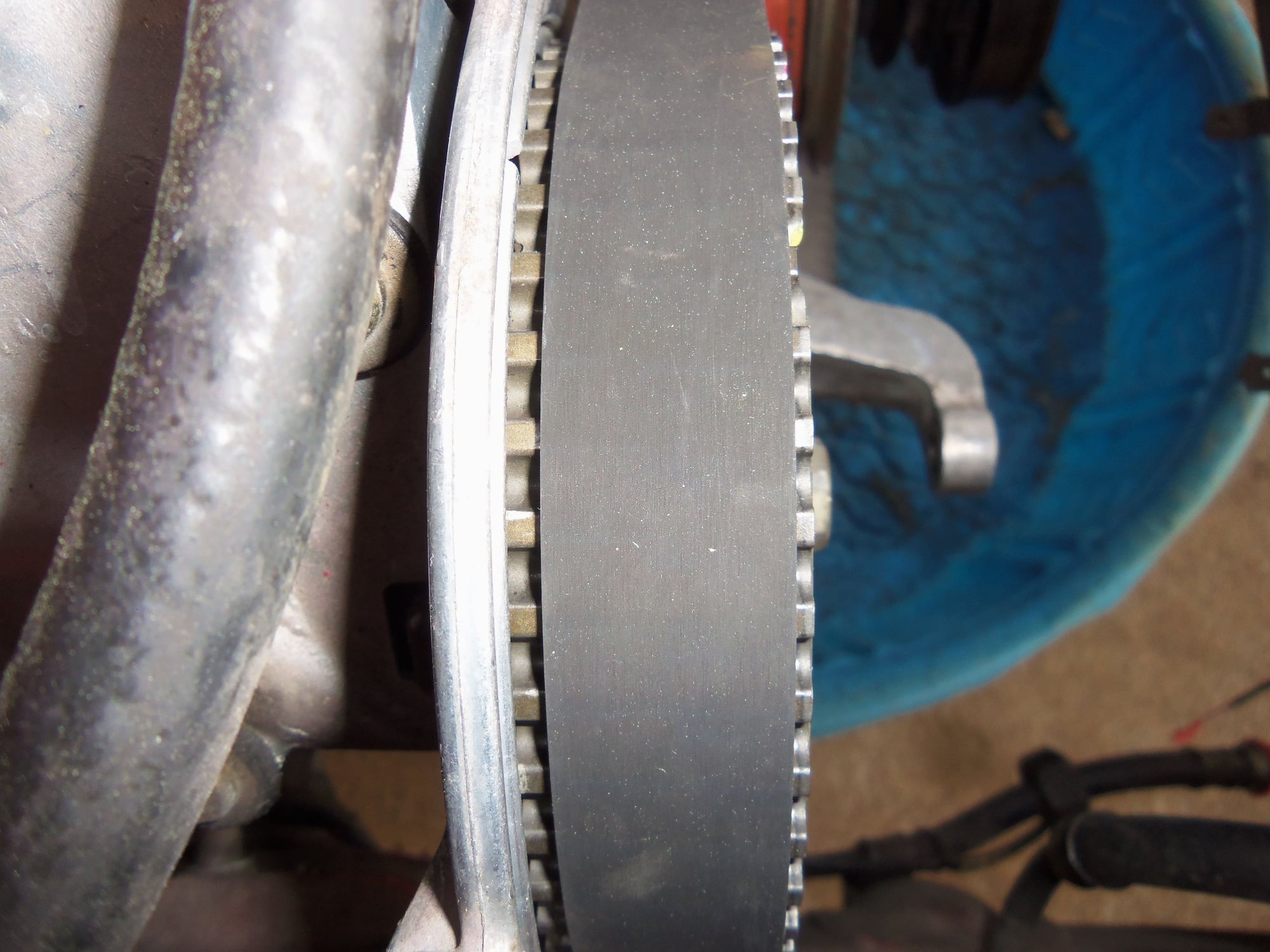
For reference: this is the tracking on the passenger's side sprocket with the old belt and misaligned tensioner roller.
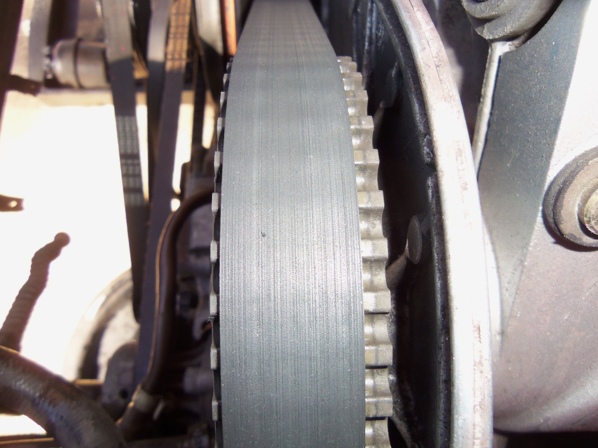
New belt tracking on the driver's side sprocket.
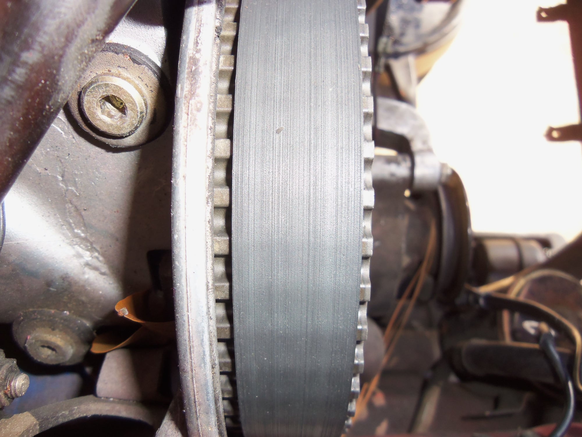
New belt tracking on the passenger's side sprocket.
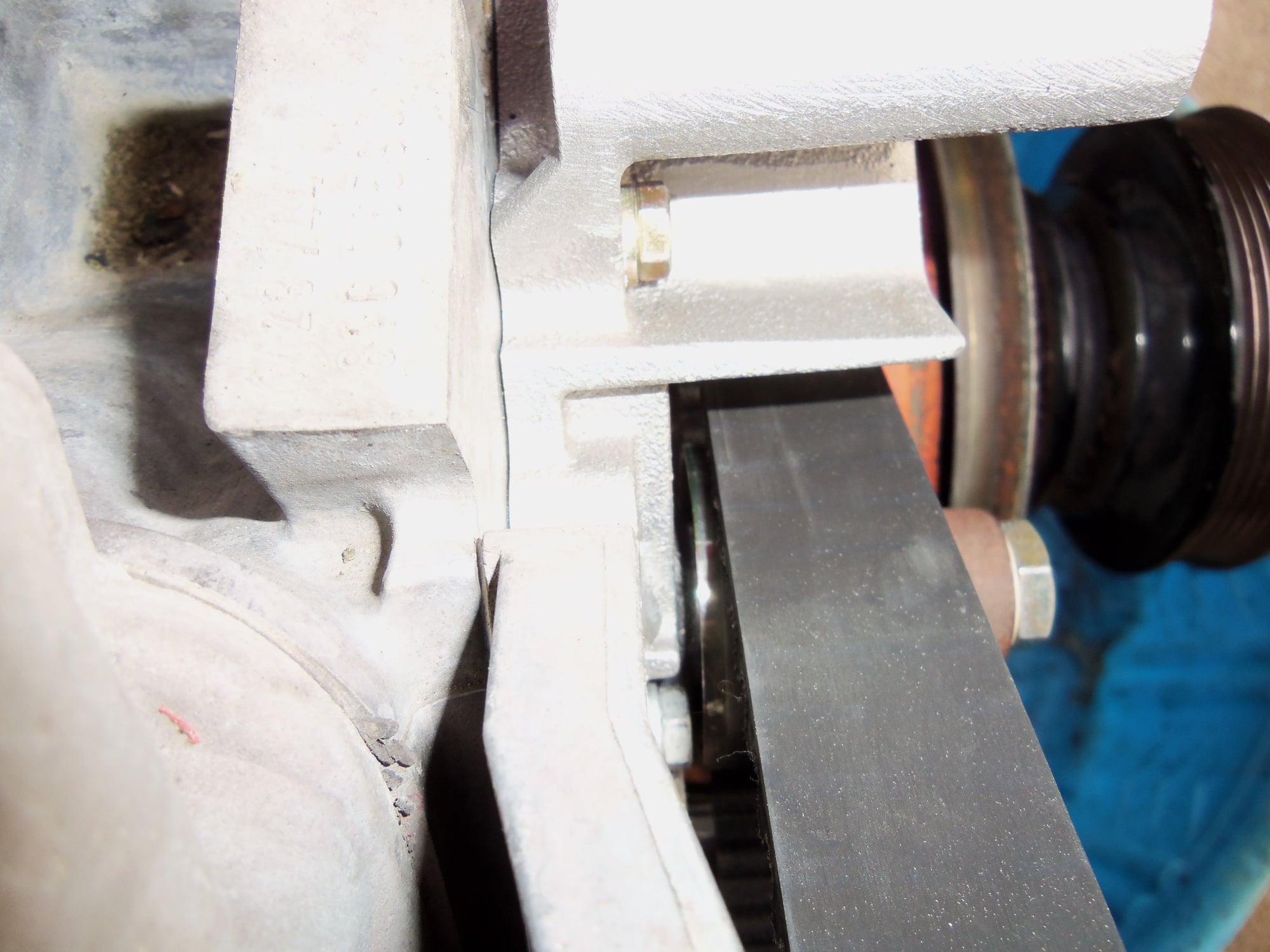
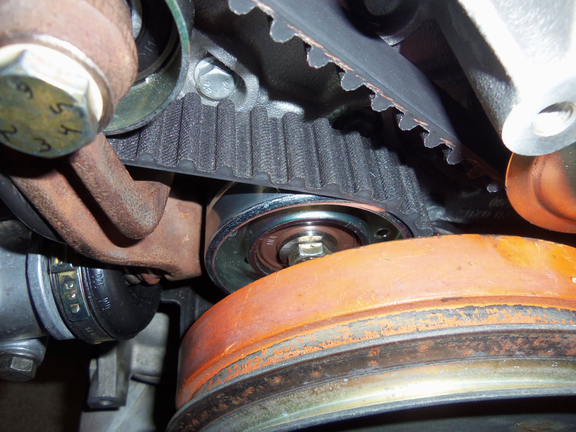
Can see a little shiny part of the back side of the tensioner roller where the belt is not riding.
Can see how the belt is tracking a little off the front edge of the tensioner roller.
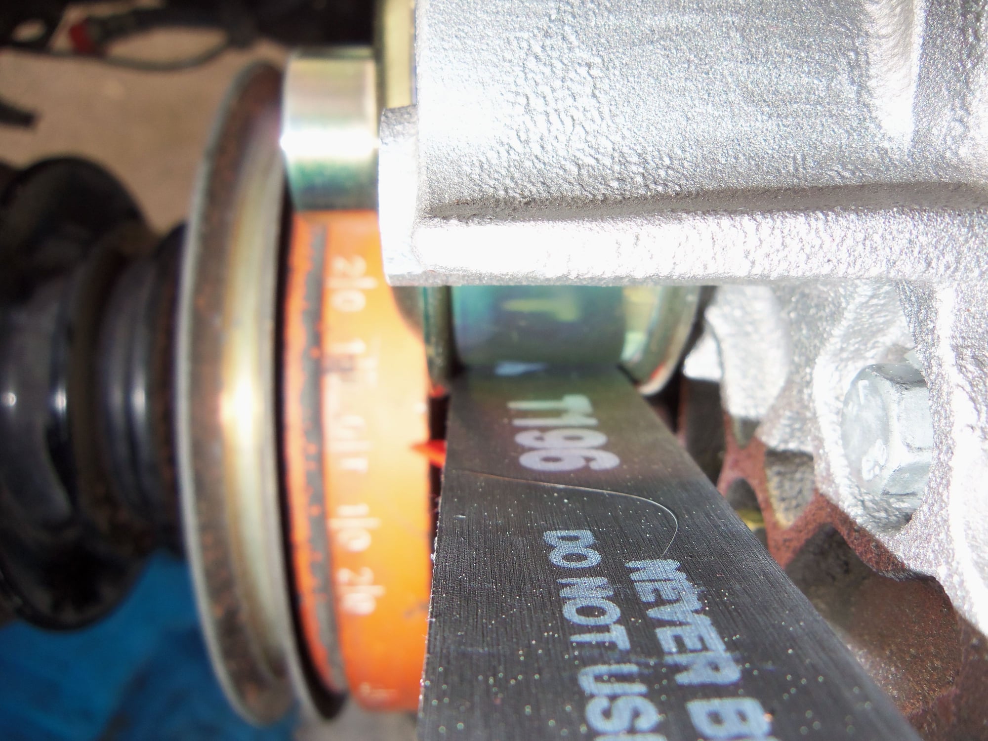
Can somewhat see how the belt is tracking towards the front lip of the water pump pulley.
I started off by removing the tensioner pivot bolt for inspection. I was able to back off belt tension enough to free up the tensioner roller. I did not want to remove the tensioner pivot bolt under pressure.
I did lightly clamp the belt to the passenger's side sprocket so it would not try to jump teeth.
With the bolt removed, I inspected the tensioner roller arm and bushings, as well as the spigot on the water pump. No issues on any of them.
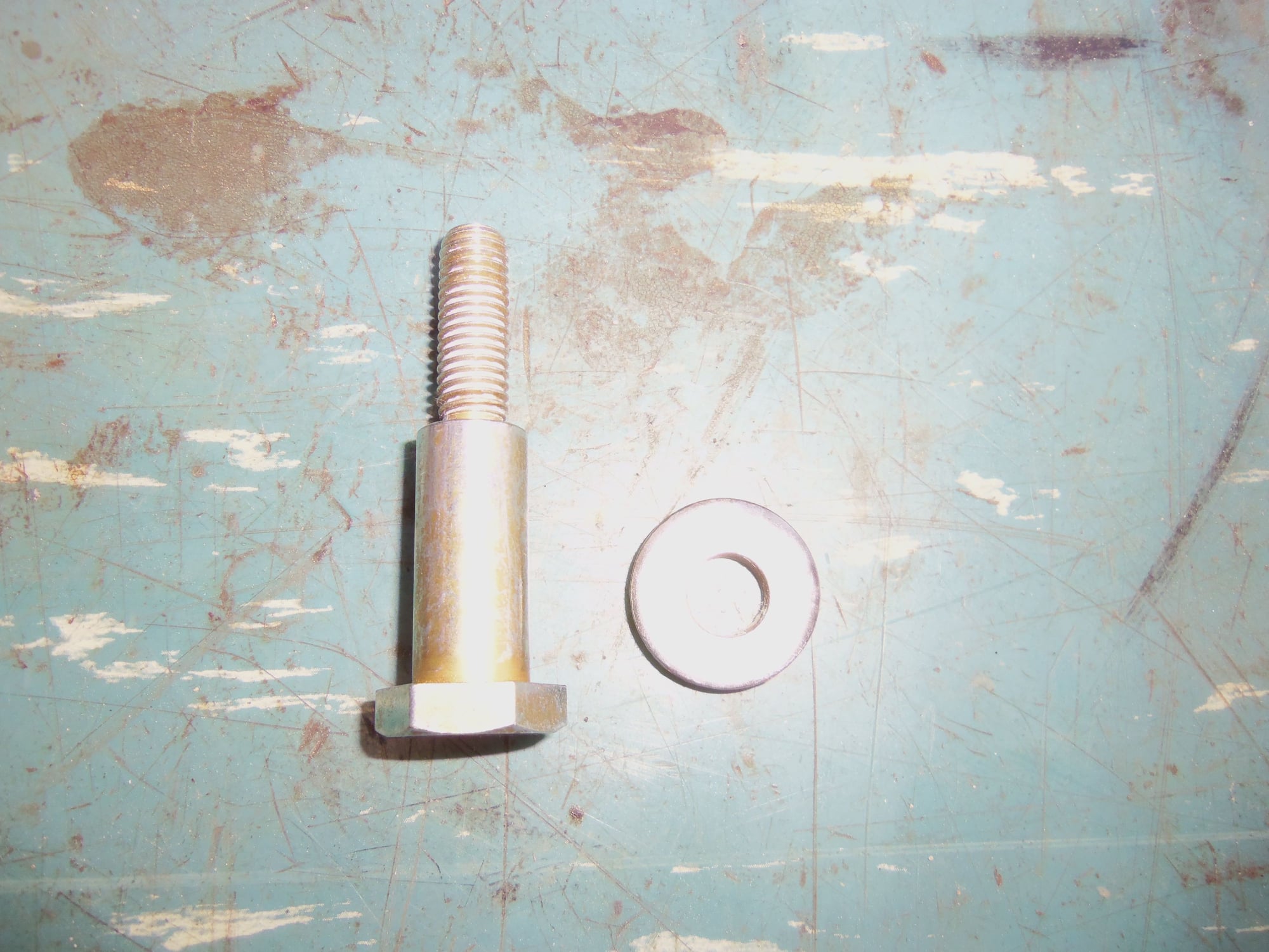
I cleaned the teflon sealant from the threads and inspected the pivot bolt closely. It did not look bent to the naked eye.
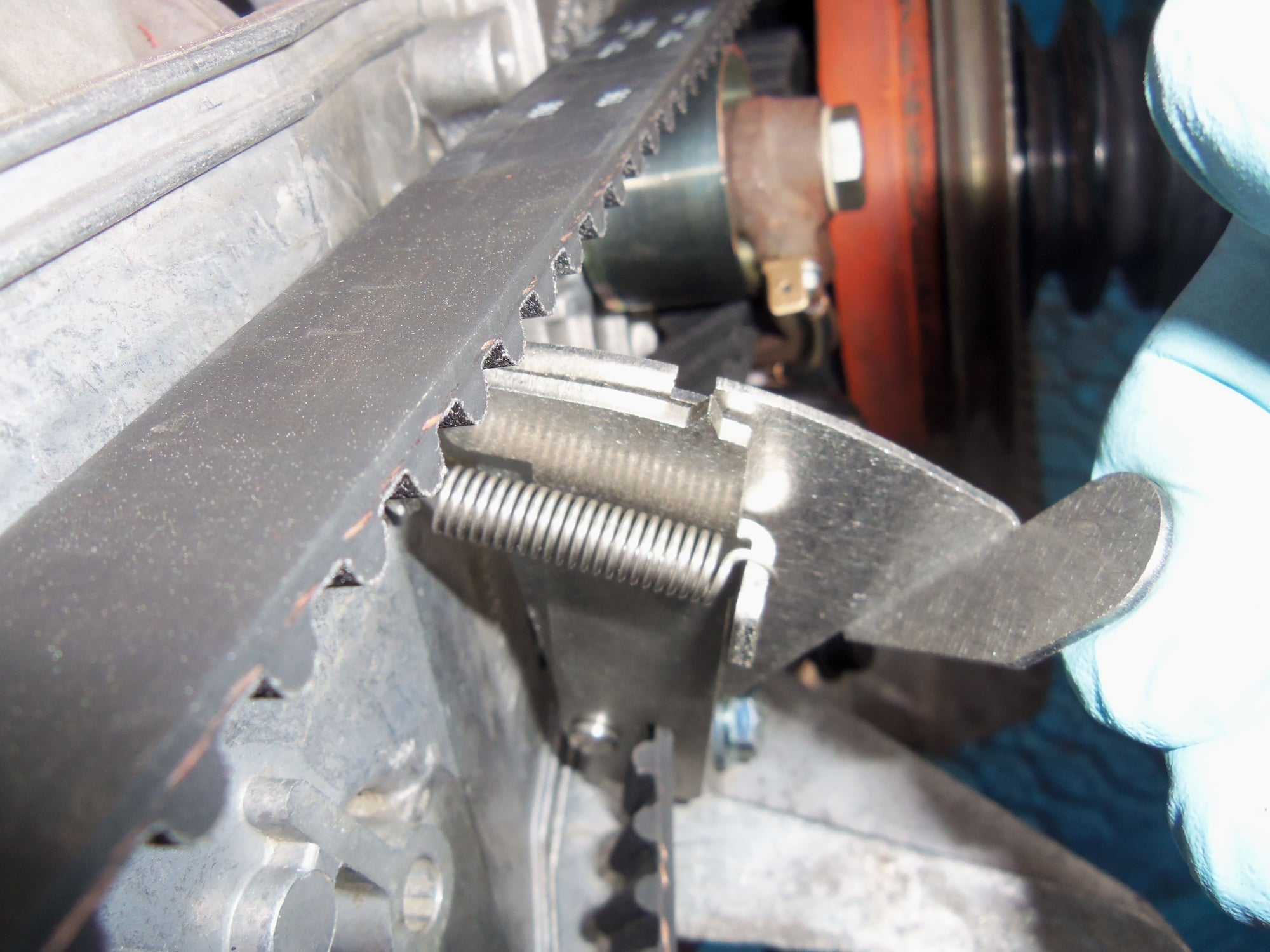
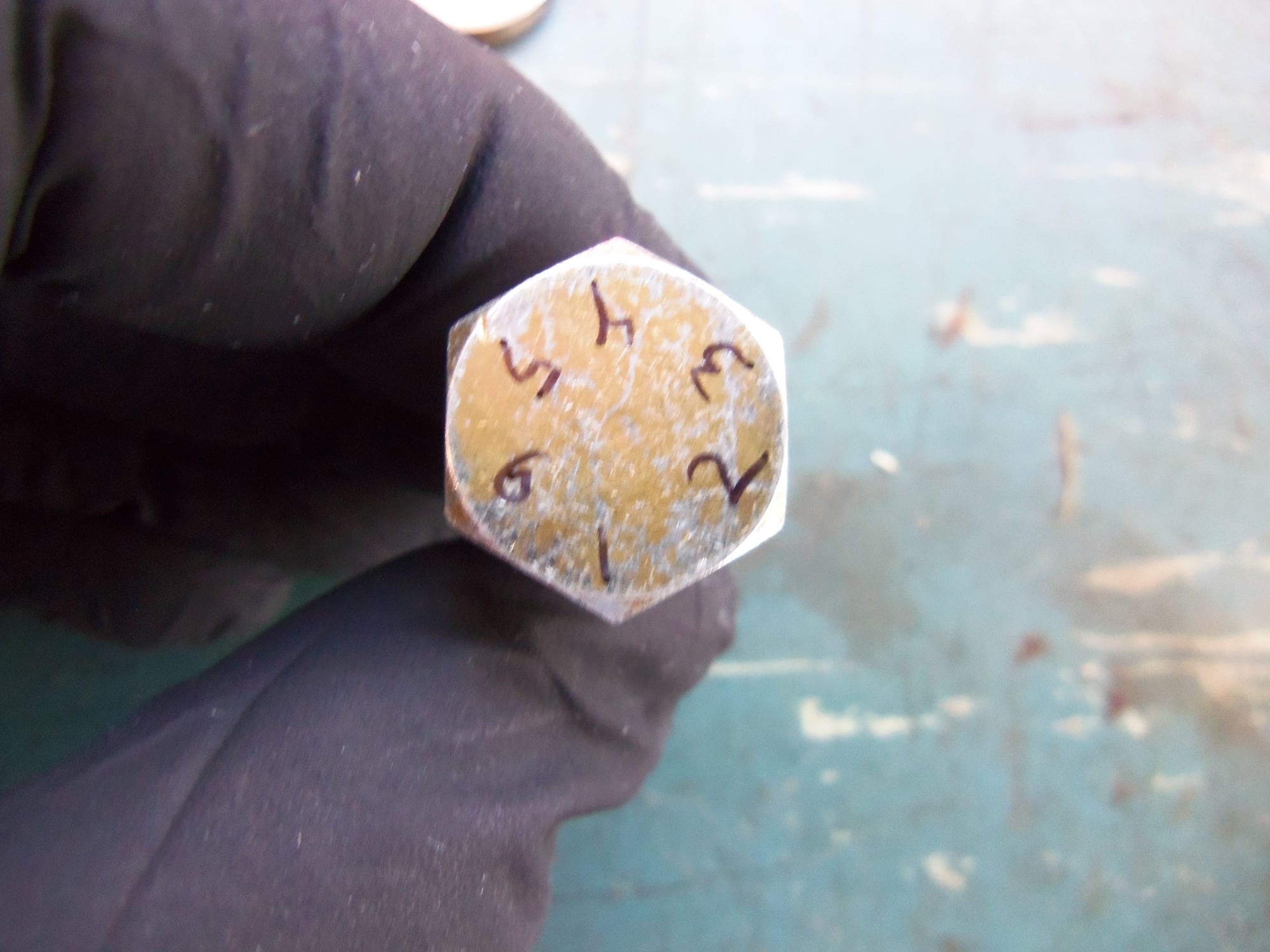
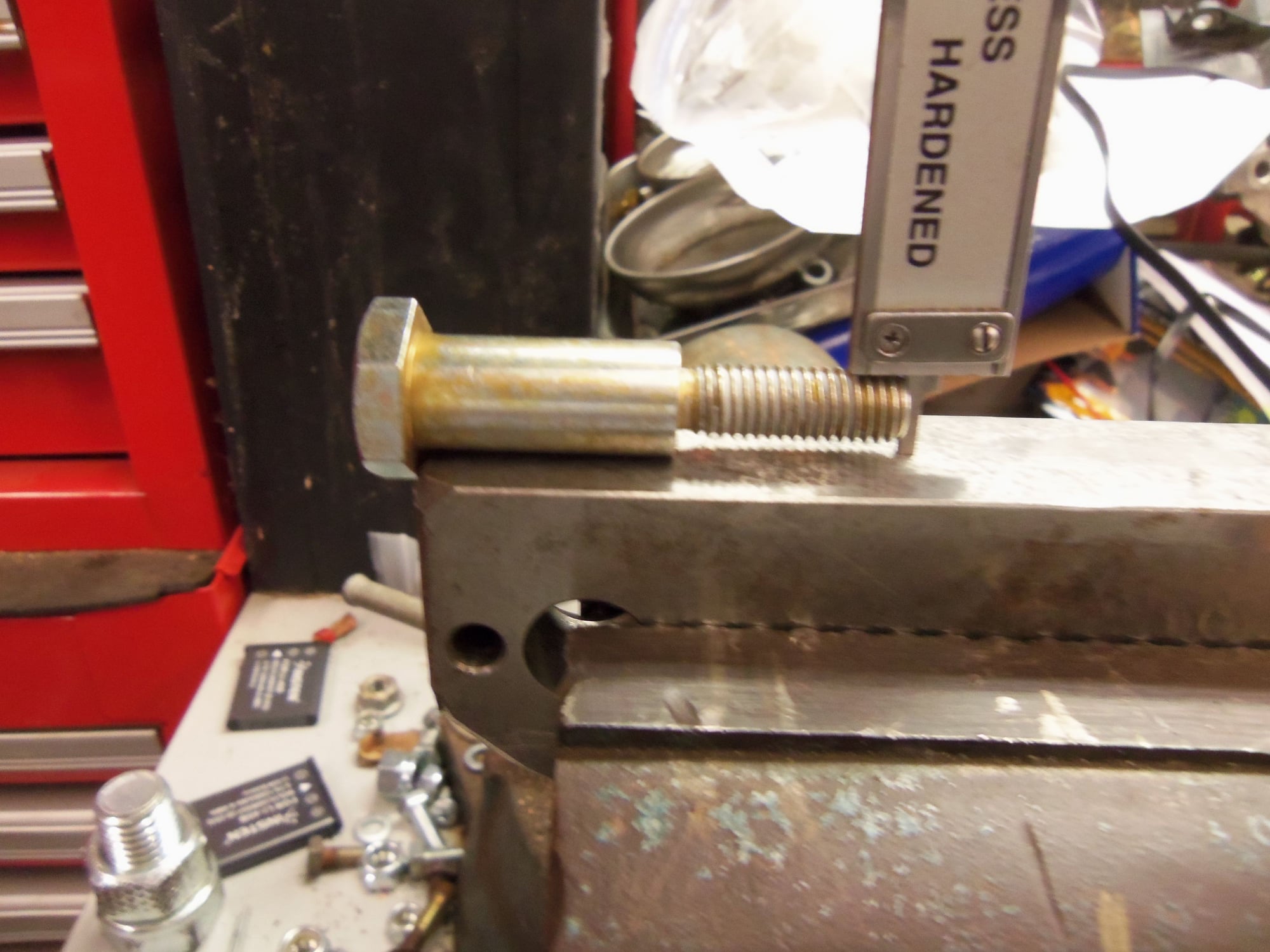
After a couple of tries, I came up with a method of accurately measuring the bolt for straightness. I numbered all six points on the top of the bolt head. I laid the shoulder part of the bolt on a straight steel block, with a point of the bolt head pointing down, hanging over the edge. Checking all six points, I measured the distance from the top of the threads to the surface of the block.
Here is what I found:
1) 9.79mm
2) 9.80mm
3) 9.82mm
4) 9.79mm
5) 9.79mm
6) 9.80mm
Given the crudeness of the measuring rig, that is a pretty consistent set of values. Based upon that, I don't think the tensioner bolt is bent.
Lightly clamped the belt to the passenger's side sprocket so it would not try to jump teeth after I released the belt tension.
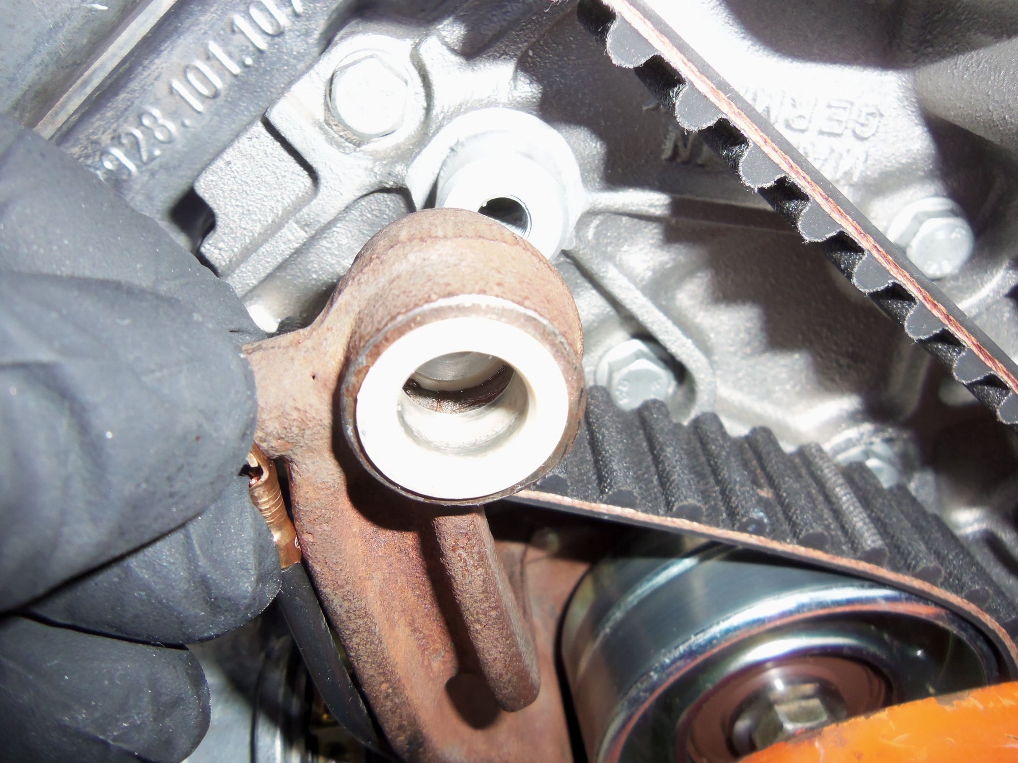
No obvious damage to the tensioner arm or the spigot on the water pump casting.
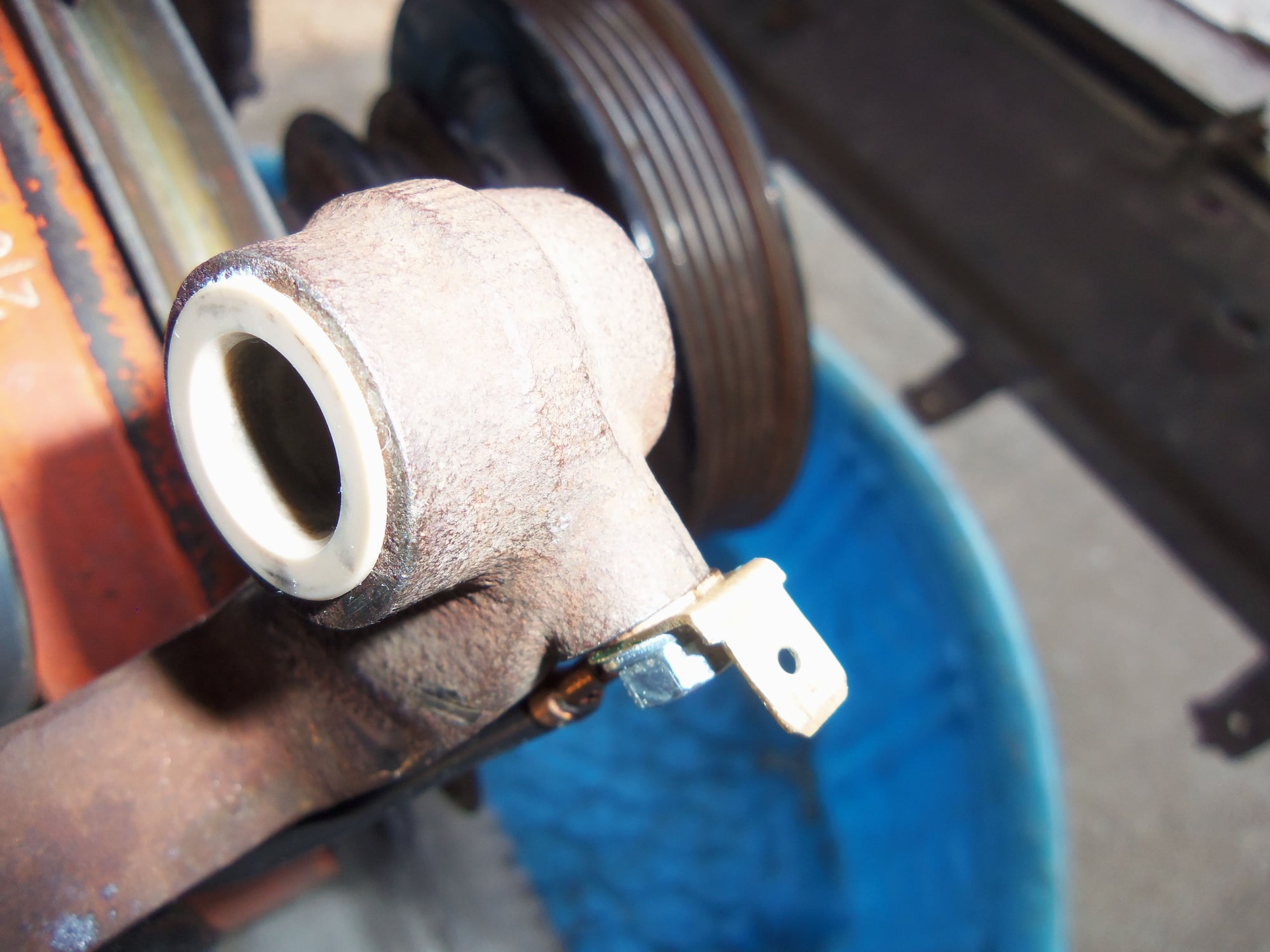
No obvious damage to the pivot bushings.
No obvious damage to the pivot bushings.
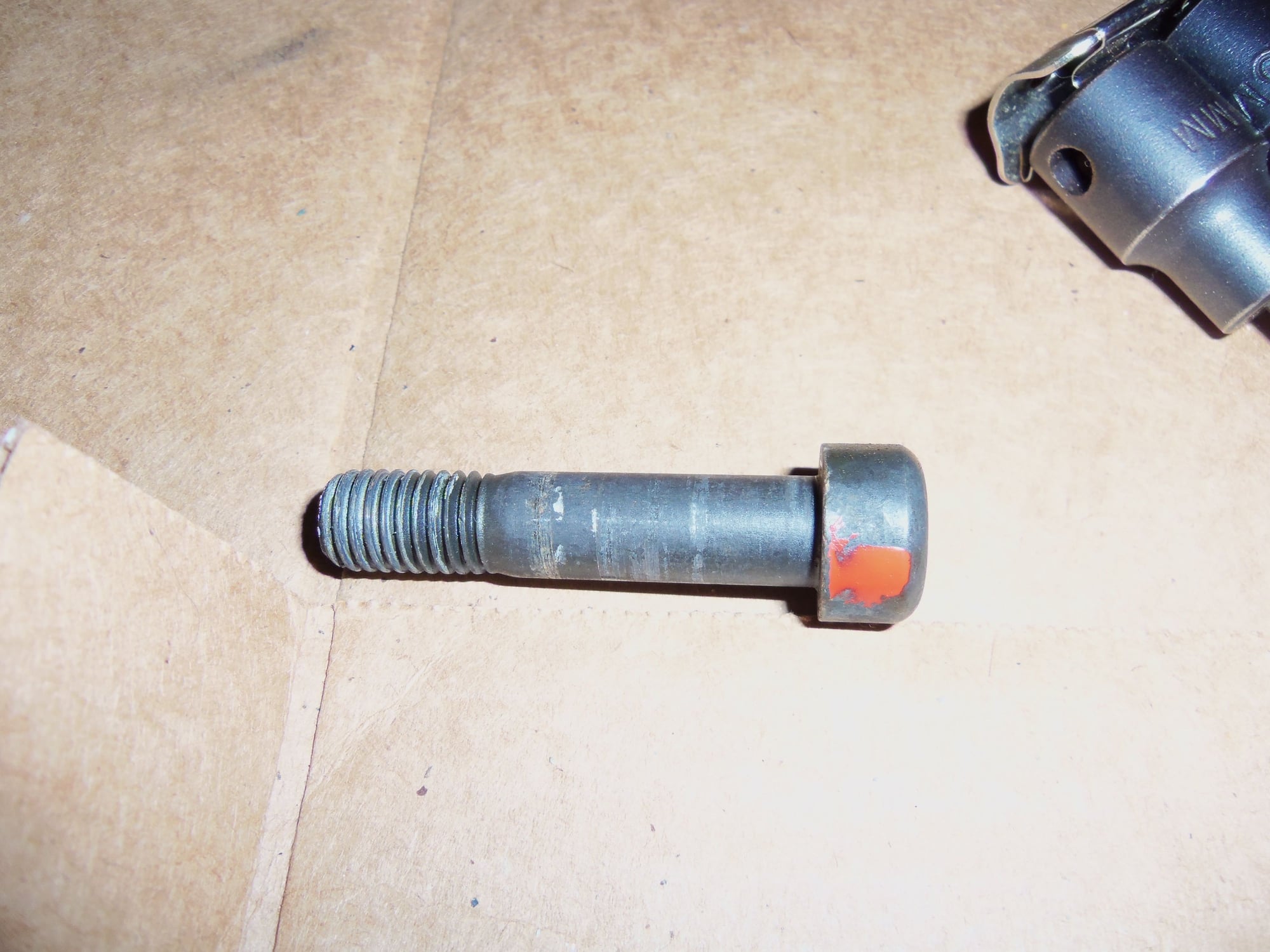
New tensioner pivot bolt shows no damage from installation, threads look straight.
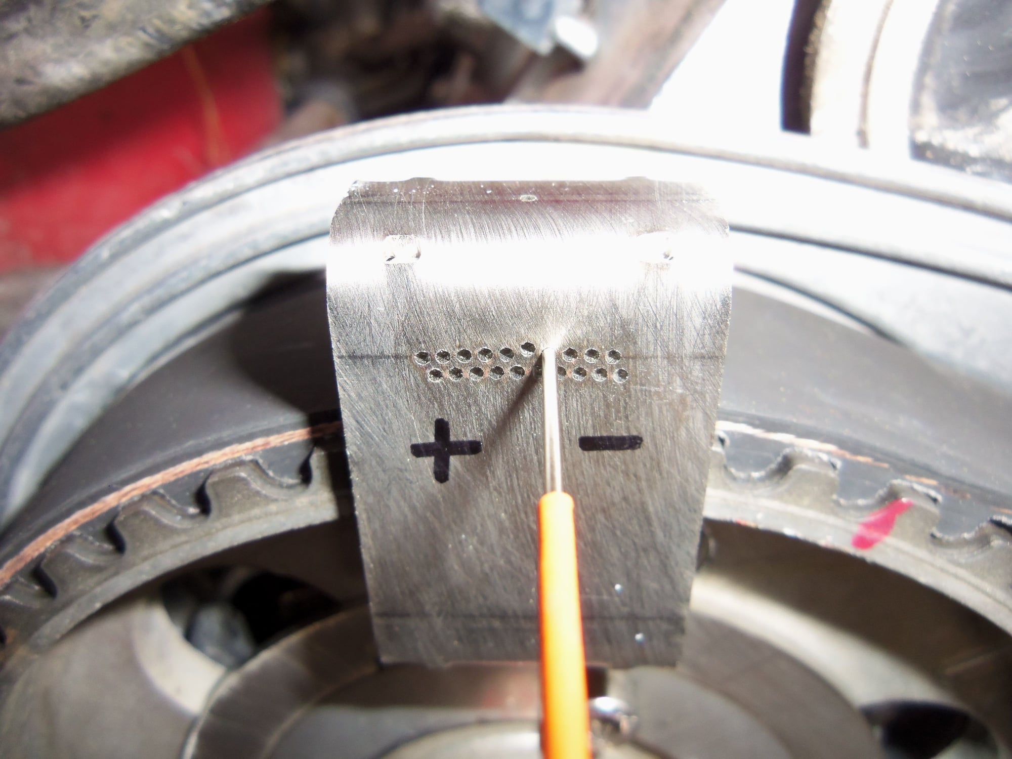
Numbered the points of the tensioner pivot bolt head.
Crude measurement rig for checking straightness of the threads of the tensioner pivot bolt.
For lack of a better idea, I reassembled everything and went through the process of tensioning the timing belt.
Man, I REALLY need to remove all eight spark plugs. This thing is a bit stiff to roll over. Many times. I will as soon as I figure out how to clean the crud out of the spark plug wells.
I did temporarily leave the roller off the spigot on the water pump. I wanted to watch how the belt traveled on the tenioner roller. I did learn that the belt was rubbing the back side of the tensioner roller bracket.
I also realized that the crank sprocket was guiding the belt to the tensioner roller. It seemed to be too far forward.
So...I took everything back apart again. I marked the belt at the 45� degree timing mark on each cam sprocket. I wanted to make it easier to realign the belt when I put it back together. I also had to reinstall the bellhousing lower cover so I could install the flywheel lock again.
I closely inspected everything as I took it back apart. I found nothing obviously wrong. I even checked the new crank thrust washers against the old washers. I was looking for some reason that the crank sprocket was guiding the belt too far forward. I found nothing. The new thrust washers matched the old thrust washers.
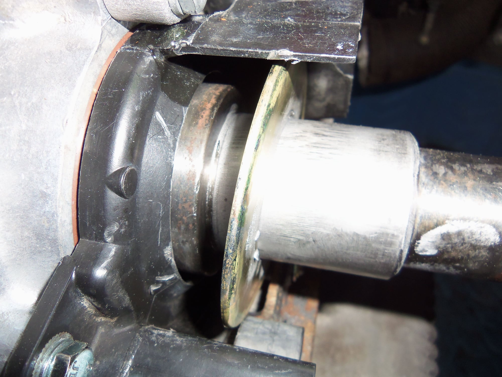
I did notice that there seemed to be alot of the crank exposed from the rear timing belt cover. Like the crank was pushed forward. That didn't make any sense to me.
Playing the 'what if' game, if the crank was pushed far enough forward to misalign the timing belt, the thrust bearing on the crankshaft should be gone...
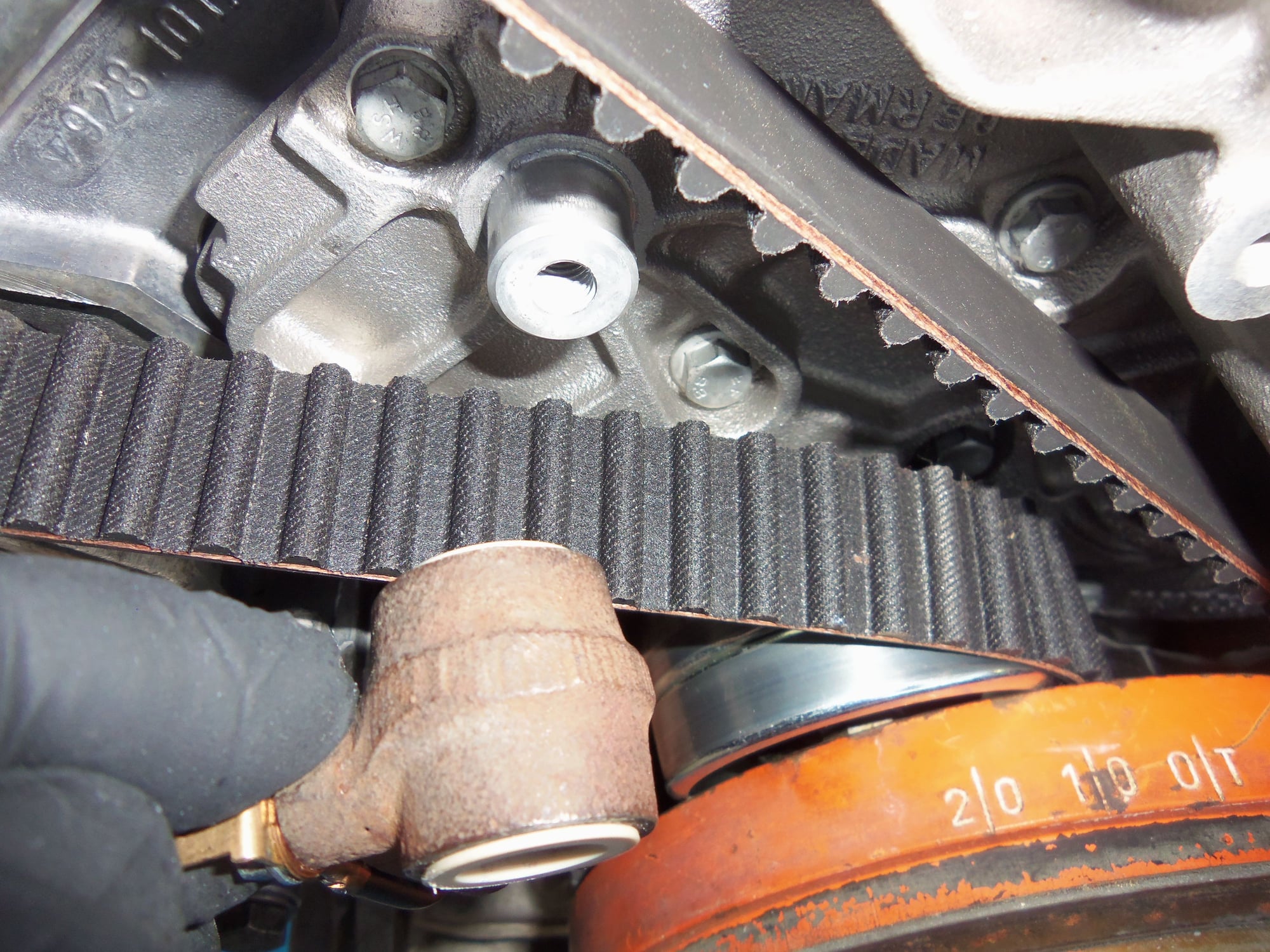
Seems to be an awful lot of the crankshaft protruding from the rear timing belt cover.
For giggles, I decided to check the flexplate for loading. I had to again remove the flywheel lock and lower bellhousing cover.
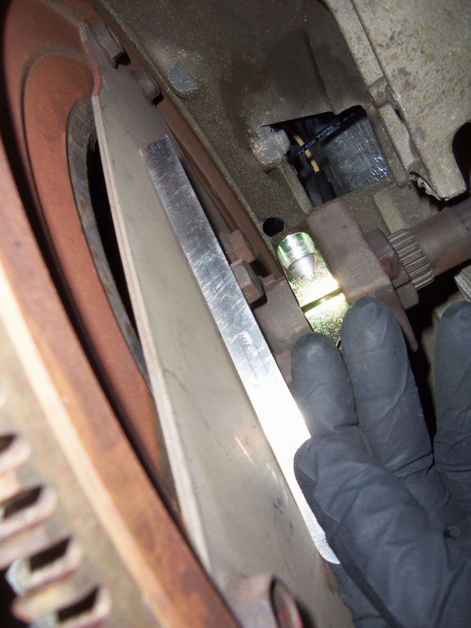
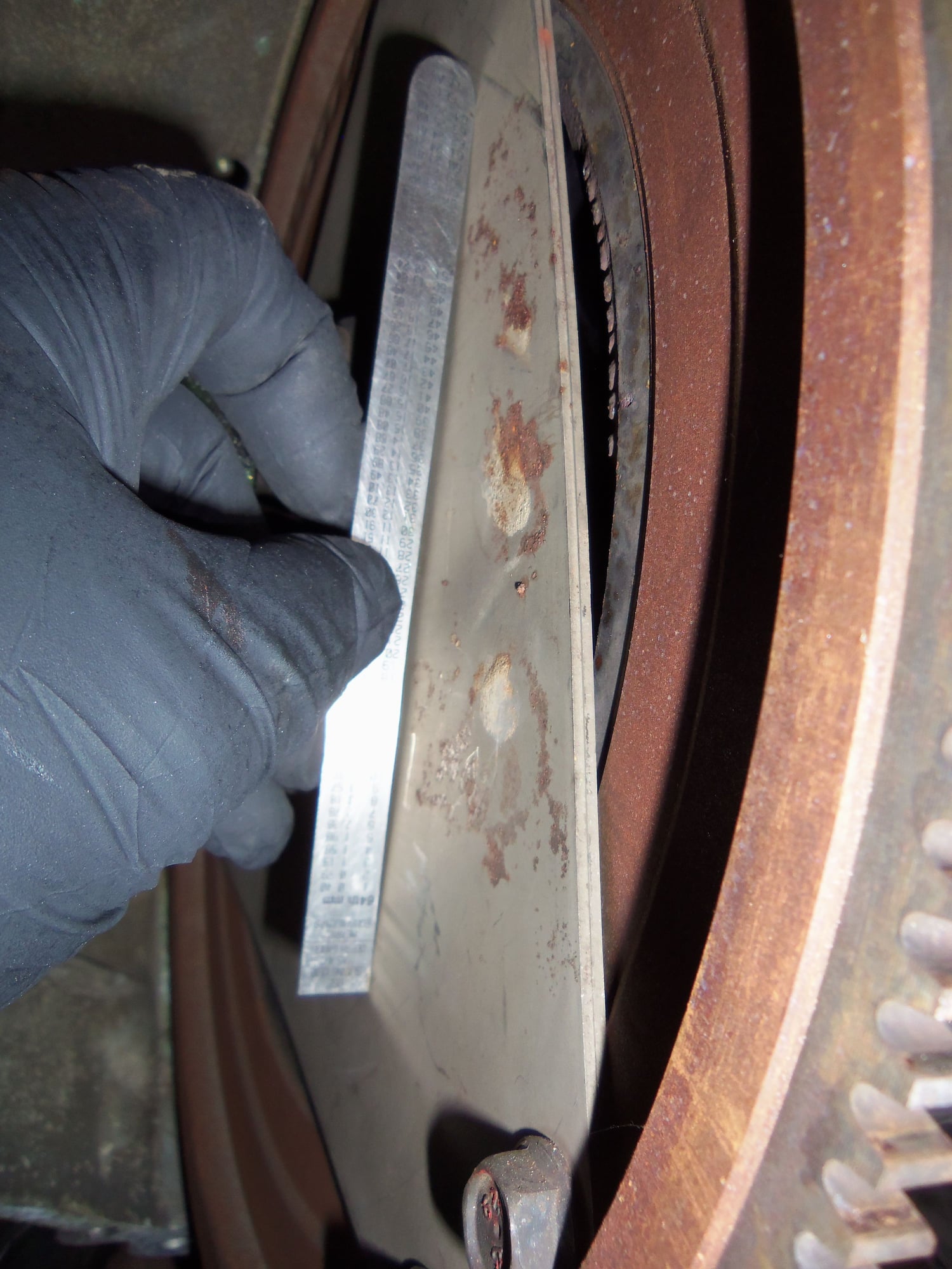
Using a small rule, I checked the flexplate.
Sonuvab*tch, it was preloaded into the crankshaft. I checked in two places.
Flexplate pressure was released 2000 miles and 11 months ago at the shop. Crank endplay was checked good and both pinch bolts were replaced.
NOTE: I added the PKlamp back in October of 2016. The engine has been run very little since then. I am going to assume the flexplate clamp migration happened before I installed the PKlamp.
Space is visible under the straight edge.
Space is visible under the straight edge.
This had to be released. But, I had to turn the crankshaft, as the flexplate clamp bolt and the PKlamp bolts were inaccessible.
So...I had to reinstall the lower bellhousing cover and flywheel lock, then reassemble the timing belt system and tension it, again.
This time, I got to experience the joy of the driver's side cam springing forward. That was alot of fun rolling it around clockwise to line it up with the 45� mark, and having it spring forward again. It took a couple of times until I was able to creep up on the 45� mark and have the cam stay where it was supposed to.
I turned the crankshaft so that the flexplate clamp and PKlamp bolts were accessible. I measured the distance from the flexplate, taken right next to the bolted flange for the flexplate clamp, to a point on the bellhousing.
Distance was approximately 86mm.
I removed the bolts for the PKlamp. I had to pry the halves off the flexplate clamp tube. I took that as a good sign, it was clamping.
I loosened the flexplate clamp pinch bolt, and saw definite movement as the flexplate released. The distance from the flexplate to the point on the bellhousing was now approximately 84mm. There was 2mm release of the flexplate.
Grrr...how in the h*ll does that happen in 2000 miles?
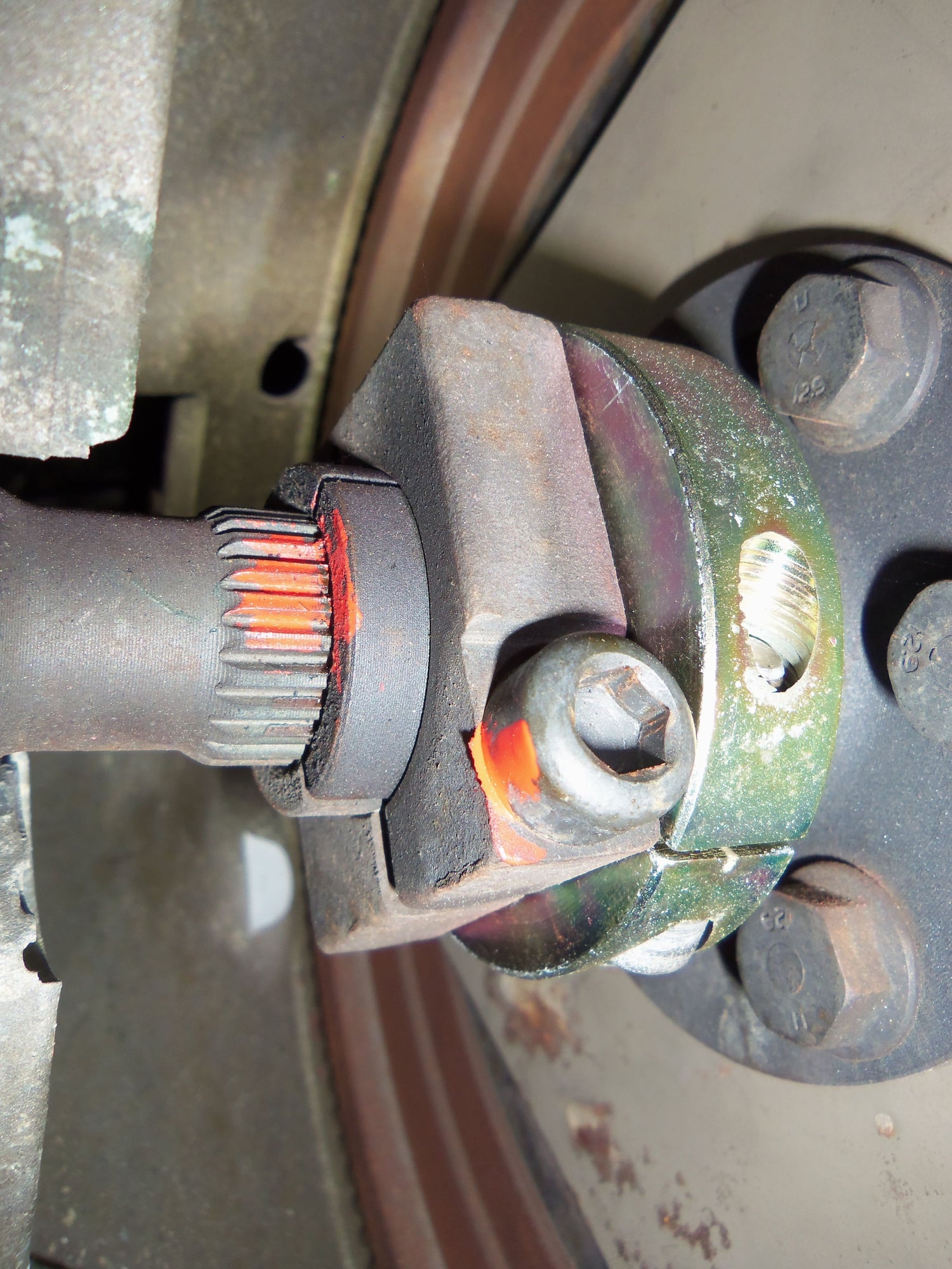
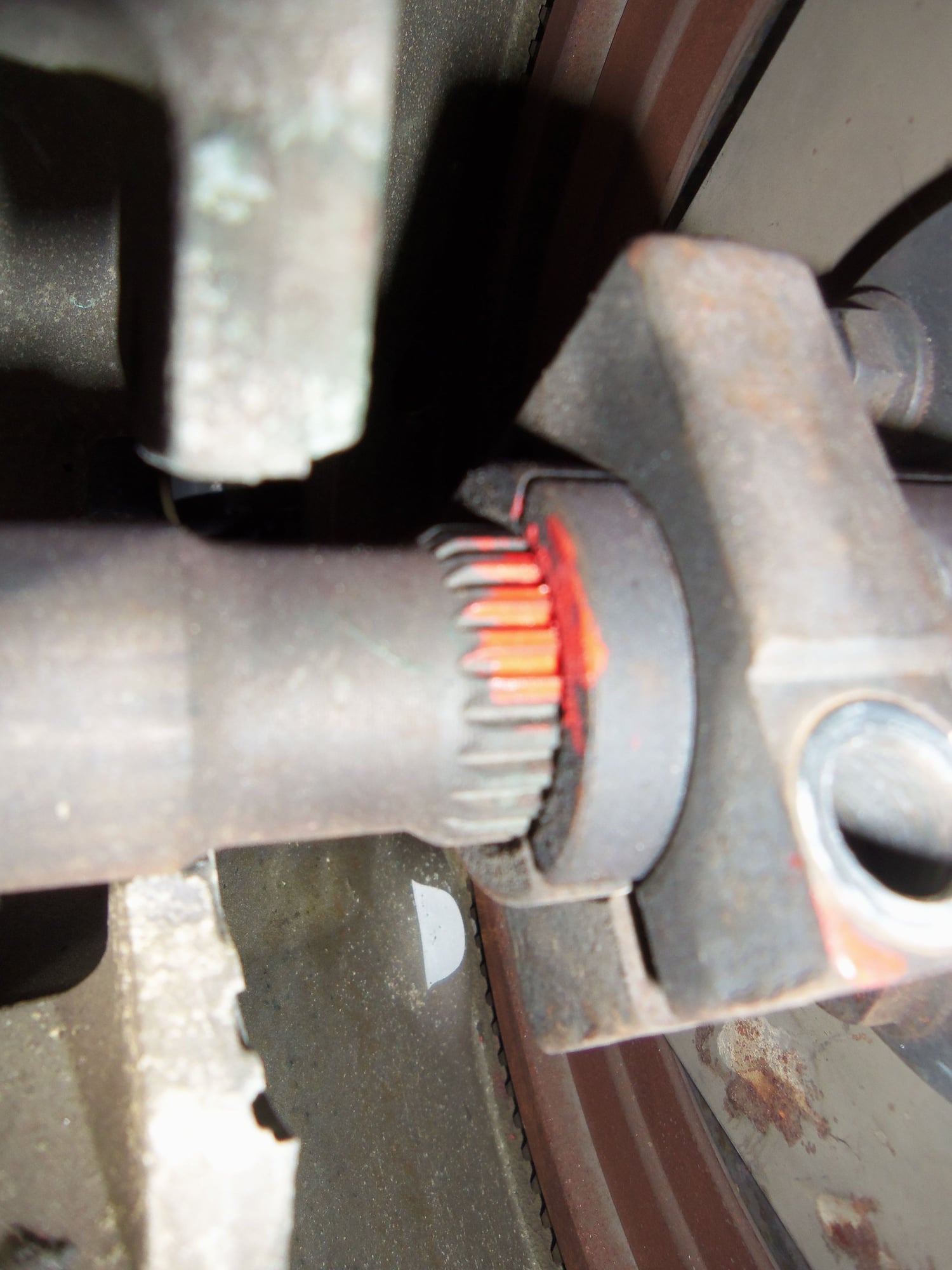
Before releasing the flexplate. You can just see where the paint does not cover the splines right up next to the clamp.
After releasing the flexplate clamp. No gap in the paint, and less spline length is visible.
New front pinch bolt shows no damage.
Having checked the front clamp and pinch bolt, I moved onto the back one.
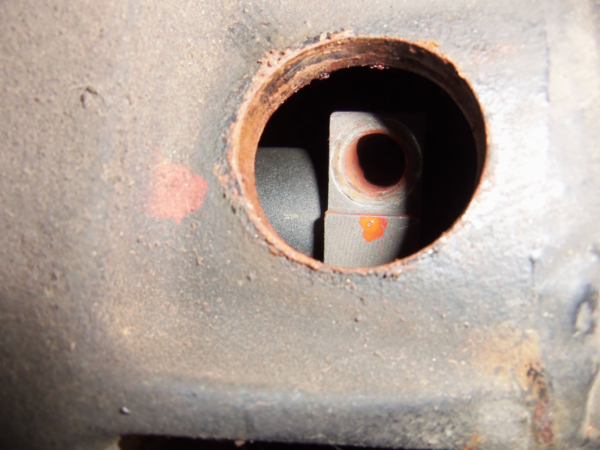
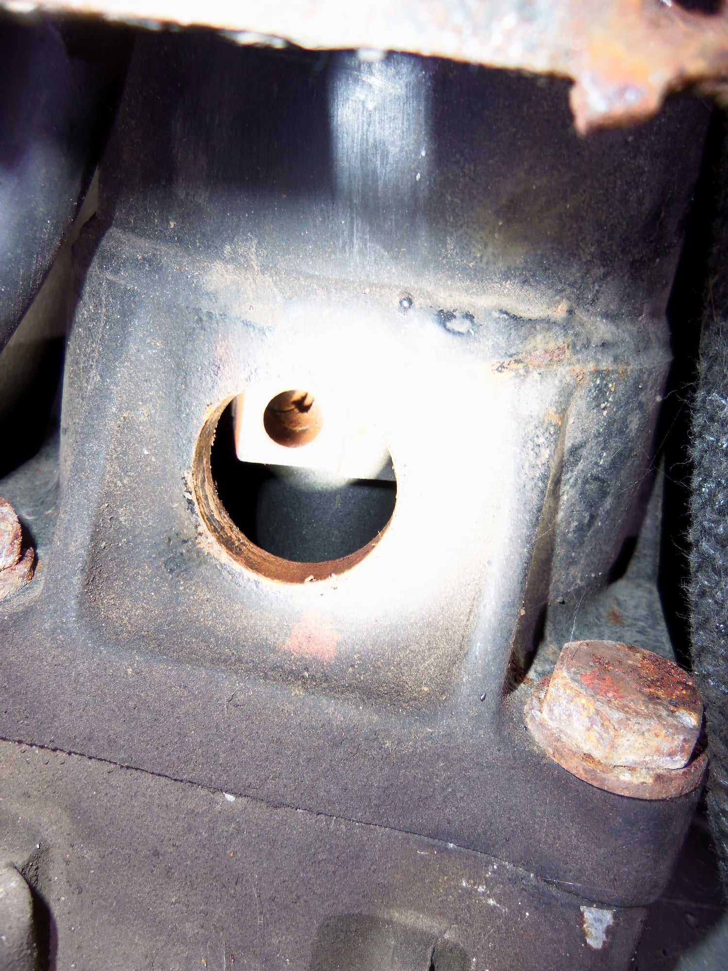
It was definitely torqued, but came out freely. There is alot of powdery rust in the hole, but the shaft cutout looks aligned with the hole in the clamp.
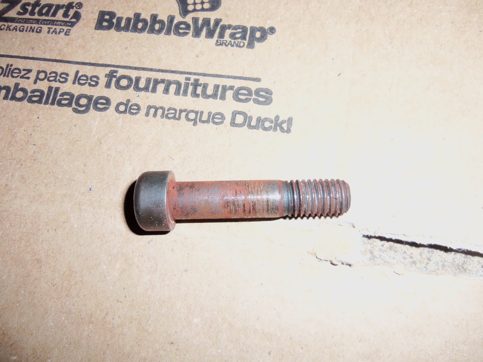
The new pinch bolt has powdery rust on it, but does not show damage and is not bent.
I am going to say that the drive shaft did not move, only the front flexplate clamp. I cleaned the bolt and reinstalled it with blue loctite. I torqued it to 66 ft/lbs.
Powdery rust in hole.
Hard to see, but cutout in drive shaft appears to be aligned with hole in clamp.
New pinch bolt has powdery rust on it, but does not appear to be damaged or bent.
I left the front flexplate clamp loose until I can properly check crank end play. I used a pry bar to move the crank back and forth to get a rough measurement of 'a little.' I will set up the dial indicator soon and get a proper measurement.
Back to the timing belt, I rolled the engine over through around ten full revolutions of the camshafts. The belt is tracking MUCH better now across the board. It looks really good on the passenger's side sprocket. There is just a hint of the belt hanging over the front edge of the tensioner roller. The driver's side sprocket definitely looks better. It is almost in the wear marks from the previous belt.
The edge of the belt is now approximately 2.8mm from the front edge of the driver's side cam sprocket.
Passenger's side cam sprocket belt tracking.
Just a hint of belt running off the front edge of the tensioner roller.
Driver's side cam sprocket belt tracking. Much better than it was!
You are not supposed to notice that I put the belt on backwards...
I don't really know what changed the tracking. I didn't do anything different when I reassembled the timing belt system. I don't understand how 2mm of preload on the flexplate could have misaligned the belt this much.

 03-20-2017, 10:00 AM