When you click on links to various merchants on this site and make a purchase, this can result in this site earning a commission. Affiliate programs and affiliations include, but are not limited to, the eBay Partner Network.
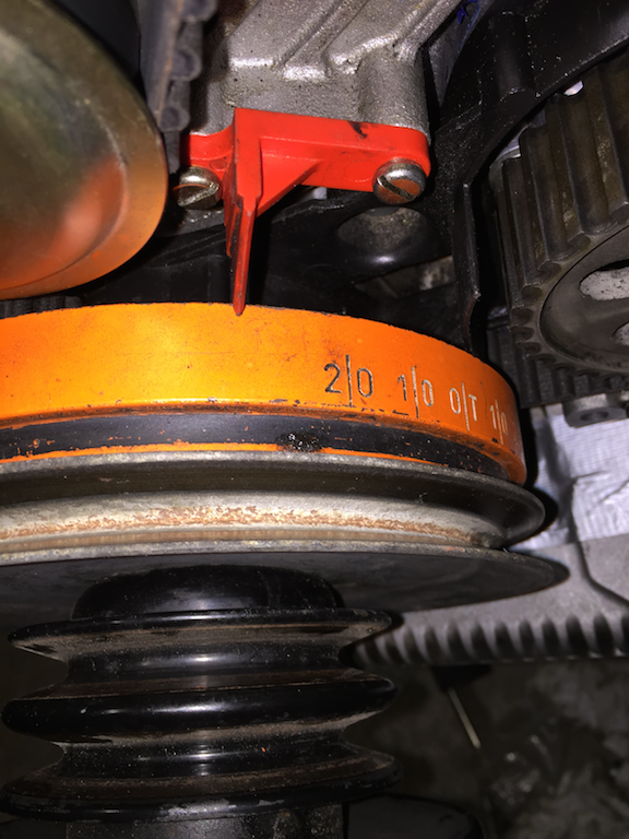
Right, I've got them dials set up and took a run. When 1 cylinder intake hits 1.6 my crank reads:
Funny thing is that I double-checked the markings on the cams AND used 9226 to set them right.
Now if I adjust the exhaust cam, I can get 1.80 when crank is at 20 After TDC but the adjustments are on the limit.
So, in the middle of night I decided to take it apart and changed intake cam one teeth advance, and now 1.60 is betweet 0 and 10 tdc. I'm seriously doing something wrong but don't know what.
May I politely suggest we first of all check the communication here-
It sounds to me as though you have used the correct setup procedure using the correct tool to align the inlet cam relative to the exhaust cam and the timing on the flywheel indicator was out by about 15 degrees of retard correct? The cam wheel has 48 teeth which means that one tooth is equal to 7.5 degrees of cam shaft travel or 15 degrees of crank travel and thus suggests you got the cam belt installed one tooth out on the 1/4 bank at least.
If I now understand what you are saying correctly you have changed the timing of the inlet cam relative to the exhaust cam-by removing the cams and resetting the position of the inlet cam relative to the exhaust cam by one tooth on the cam sprocket going by what you have written - is this correct given this seems a strange thing to do?
Given your first photo with the flywheel at about 35 degrees past TDC this would suggest to me that you had the timing belt one cog out on the cam wheel for 1/4 bank and that is where I would have been suspicious. Where are the timing marks on the cog relative to the timing mark on the back cover?
Kindly clarify what exactly you did last night and then we can take it from there.
NOTE this is the front plug on the right side of the engine when sitting in the car.
Carefully put a straight piece of coat hanger 12 inches long into the plug hole and turn the crank to the O/T location and see if the piston is also at TDC,
NOTE the wire will be pushed out of the hole when the piston reaches TDC.
What your doing is to verify that you have the crank actually set at TDC.
NOTE its possible that crank damper could have moved ( broken the bond of the rubber)and thus what your looking for is not what your getting.
Once the TDC is verified remove the wire and install the plug.
Then fit the cam belt so the cams are lined up to the respective marks,
use a zip tie on the left cam pulley to hold the belt in place while you install the right side cam
use a 32MM wrench on the fat washer under the cam pulley bolt to turn the cams as needed
First of all, tnx guys for helping me out. The support I have received on this forum is really good stuff.
Originally Posted by FredR
It sounds to me as though you have used the correct setup procedure using the correct tool to align the inlet cam relative to the exhaust cam and the timing on the flywheel indicator was out by about 15 degrees of retard correct?
Correct.
Originally Posted by FredR
The cam wheel has 48 teeth which means that one tooth is equal to 7.5 degrees of cam shaft travel or 15 degrees of crank travel and thus suggests you got the cam belt installed one tooth out on the 1/4 bank at least.
What we did is to put crank to 45' mark, then align cam pulleys to align with the markings on the covers (rear mark of the pulleys). After this was done, we put the crank to 0' and put the cam belt on. Adjusted tension and rotated engine couple times in between. Then we put the dial on the inlet of the cyl:1 , set the preload to 5.00 mm and started turning the engine. When we were at 1.60 on the dial, crank was showing what you can see in the picture.
Funny enough, if I twist the cam to edge of the limit (distributor bolts) we can get 1.80 on the cylinder 1, which is about ok for '87-> cams but this is S3 setup so we should have 1.60, right?
Originally Posted by FredR
If I now understand what you are saying correctly you have changed the timing of the inlet cam relative to the exhaust cam-by removing the cams and resetting the position of the inlet cam relative to the exhaust cam by one tooth on the cam sprocket going by what you have written - is this correct given this seems a strange thing to do?
Yes. It was one of those 'in the middle of night' ideas at garate. As end result we can see that 1.60 at inlet of cylinder 1 is when crank is at 0' TDC (almost)
Originally Posted by FredR
Given your first photo with the flywheel at about 35 degrees past TDC this would suggest to me that you had the timing belt one cog out on the cam wheel for 1/4 bank and that is where I would have been suspicious. Where are the timing marks on the cog relative to the timing mark on the back cover?
The markings on the rear of them pulleys are aligned with the ones on the cover.
Originally Posted by FredR
Kindly clarify what exactly you did last night and then we can take it from there
Rgds
NOTE this is the front plug on the right side of the engine when sitting in the car.
Carefully put a straight piece of coat hanger 12 inches long into the plug hole and turn the crank to the O/T location and see if the piston is also at TDC,
NOTE the wire will be pushed out of the hole when the piston reaches TDC.
What your doing is to verify that you have the crank actually set at TDC.
NOTE its possible that crank damper could have moved ( broken the bond of the rubber)and thus what your looking for is not what your getting.
Once the TDC is verified remove the wire and install the plug.
Then fit the cam belt so the cams are lined up to the respective marks,
use a zip tie on the left cam pulley to hold the belt in place while you install the right side cam
use a 32MM wrench on the fat washer under the cam pulley bolt to turn the cams as needed
I'm going there next friday, going to do some preparations before (new versions of the 9226 tool etc) just to be sure. I'm quite confident I had the cams aligned correctly on the first run ; markings on the cams measured exactly 113mm with a caliber set on the syncronisation marks. But, first I'll check where TDC actually is.
Last edited by JakeS2; 10-07-2015 at 07:37 AM.
Reason: Typoed the distance from markings 133->113.
NOTE at this point the least amount of turning the engine crank should be paramount,
so you dont chance bending a valve.
In other words turn the crank either direction to get to TDC with the least amount of turning
"What we did is to put crank to 45' mark, then align cam pulleys to align with the markings on the covers (rear mark of the pulleys)."
I hope that there is a failure to communicate...
There are no cam sprocket marks at 45 deg unless someone has added them. The only cam sprocket marks from the factory are at TDC.
Something is not reading correctly here. Whether it is communication or incorrect technical procedure we need to clarify.
Step 1: Place the crank at 45 before top dead centre No 1 cylinder [done]
Step 2: Mount the cams using the special tool as per workshop manual [done?]
Step 3: Fasten the cam wheels to the exhaust cam shafts set in roughly mid adjustment position and tighten down.
Step 4: Fit the timing belt and then remove the special alignment tool
Step 5: Move the engine forward to TDC-check that the timing marks on the cam wheels roughly align with the notches in the back cover.
Step 6 Move the engine forward to 20 degrees after TDC and check that the lift on the cam is correct and if not adjust the timing on 1/4 bank until correct lift has been realised then move on to the 5/8 bank asper WSM procedure and check that.
if the cams are not aligned correctly then depending on how far out they are the valves will touch pistons at some point- not sure at what point that happens but be very wary about fully rotating the engine until you are sure where you are in this process.
Trust I have defined the steps correctly-please advise if you have done anything different- note it is very easy to get the belt one tooth out but note the belt has to be strung whilst the crank is at 45 degrees BTDC- that is how I did it. Doubtless someone will correct me if I have called it incorrectly.
If in doubt do not move the motor until a recovery procedure is agreed.
i want to see a picture of the cams and how they made that cam fit the more narrow bearing area.
at 2-3 teeth off, you still can rotate the crank without the pistons hitting the valves.
i had a similar situation in adjusting the valves, and was fighting Ken for a long time until i realized i was taking a short cut in rotating the crank. (just starting out at 45degrees and moving forward) you need to do that full 2 revolutions to get an accurate reading on the total lifter (valve) movement.
[QUOTE=mark kibort;12652665]i want to see a picture of the cams and how they made that cam fit the more narrow bearing area.
QUOTE]
Mark,
On one of the cams you have to fabricate/fit a thrust collar- My memory tells me it is the 5/8 exhaust cam but I could be wrong on that. You also have to remove the rear support journal [or activate the lubrication for that journal position] on each cam. The cams are then a direct bolt in affair.
i want to see a picture of the cams and how they made that cam fit the more narrow bearing area.
QUOTE]
Mark,
On one of the cams you have to fabricate/fit a thrust collar- My memory tells me it is the 5/8 exhaust cam but I could be wrong on that. You also have to remove the rear support journal [or activate the lubrication for that journal position] on each cam. The cams are then a direct bolt in affair.
Rgds
Fred
fred, yep, i know the procedure all too well. i had elgin do mine matching the dimensions of an old set of S4 equiv cams.
i just wanted to see how they did it on his cams. yep, and then just lap off the end of all of the cams near the firewall. (no bearing back there on the S4)

 10-05-2015, 04:34 AM