When you click on links to various merchants on this site and make a purchase, this can result in this site earning a commission. Affiliate programs and affiliations include, but are not limited to, the eBay Partner Network.
It clearly states at 1:07-> to align the cams to index marks while crank is at 45' before TDC. After that it tells to put crank to 0 TDC and mount the belt. What am I not getting here?
Originally Posted by FredR
Jake,
Something is not reading correctly here. Whether it is communication or incorrect technical procedure we need to clarify.
Absolutely agree!
Originally Posted by FredR
Step 1: Place the crank at 45 before top dead centre No 1 cylinder [done]
Check.
Originally Posted by FredR
Step 2: Mount the cams using the special tool as per workshop manual [done?]
Check, with a cardboard version but nevertheless done.
Originally Posted by FredR
Step 3: Fasten the cam wheels to the exhaust cam shafts set in roughly mid adjustment position and tighten down.
Check.
Originally Posted by FredR
Step 4: Fit the timing belt and then remove the special alignment tool
Now this is where it gets confusing. Do I do it this way or the video? Or am I just somehow lost and don't see the point?
Originally Posted by FredR
Step 5: Move the engine forward to TDC-check that the timing marks on the cam wheels roughly align with the notches in the back cover.
Step 6 Move the engine forward to 20 degrees after TDC and check that the lift on the cam is correct and if not adjust the timing on 1/4 bank until correct lift has been realised then move on to the 5/8 bank asper WSM procedure and check that.
Right, that part I can understand, but the steps to put on the belt is news to me and thus not visible on the video (which assume is legit?)
Originally Posted by FredR
if the cams are not aligned correctly then depending on how far out they are the valves will touch pistons at some point- not sure at what point that happens but be very wary about fully rotating the engine until you are sure where you are in this process.
Yes, due to this I'm ready to reboot the whole procedure starting with cams off the engine, with new (more precise cut) sample of the 9226 tool.
Originally Posted by FredR
Trust I have defined the steps correctly-please advise if you have done anything different- note it is very easy to get the belt one tooth out but note the belt has to be strung whilst the crank is at 45 degrees BTDC- that is how I did it. Doubtless someone will correct me if I have called it incorrectly.
If in doubt do not move the motor until a recovery procedure is agreed.
Rgds
Fred
I'm happy to follow on those steps to get this straight. Will post results (or WTB:new engine post ) during wknd.
I refer the sequence I took nearly 10 years ago when re-building my S4 motor and putting it in the GTS chassis but I need to ensure that what I remember is correct as I would hate to be giving inappropriate advice. Had a look at the video and can see why you are confused. I would not dream of moving the crankshaft away from 45 BTDC without the belt engaged and the cams in the correct position- my understanding is that the index marks on the cam shaft body place the cams in the correct position to mount the cam wheels and then the belt at the 45 BTDC position but that is not specifically stated in the manual. What I can say is that when the crank is at 45 BTDC the cam wheels have to be 3 cam wheel teeth before [i.e to the right of] the index mark when fitting the cam belt and then when the assembly is forwarded to TDC, the notches should align perfectly with the notch on the back casing and if they do not then no point in doing the final clock gauge adjustment.
When I do the timing belt and have the cam wheels off I have the crank locked at 45 BTDC and would never move the crank until the belt is back on in the correct position. Now I am wondering if I am [falsely] assuming the cams are in the correct position [at 45 BTDC] with the notches on the cam body aligned as per the manual. For your info I put a white paint mark on the cam tooth that aligns with the notch on the casing when the crank is at 45 BTDC. I also use the 32VR cam timing tool knowing that my cams were timed correctly to start with and can use the tool with confidence knowing it is accurate. If I was to fit the S3 cams I would initially revert to the dial gauge method to get a correct benchmark and thus know where the datum position is for future timing events using the 32VR kit.
I also went through this procedure a while ago when contemplating whether to install my S3 camshafts in the motor. As yet never got round to modifying them but I run the GTS inlet cam with the S4 exhaust cam - a halfway house so to speak.
Before writing my notes to you I also went through the WSM once more to make sure I had not missed or misquoted you anything.
Upon reading the WSM again, to my astonishment I noticed that it does not specifically state that after mounting the cams into position you you should then install the cam belt! Thus we must ensure that what I understand to be the case is correct- hopefully someone will chime in here. It makes no sense to me to put the crank in a safe position [45 degrees] and then turn the crank with the cams static- if that was expected I would expect the manual to state so very clearly. I must assume that the video knows that if the pistons are at 45 BTDC you can safely move the cams to the TDC position and then move the crank safely to TDC but this leaves me wondering why one would do this when there is seemingly no need. This supports Mark's statement that you can safely move the crank forward to TDC independent of the cams for 45 degrees of travel. Seems to me the WSM is a bit vague here.
I have no idea why Porsche recommend special tool 9226 to hold the S3 cams- perhaps it is required because the LSA is wider on these cams [?] but this tool was allegedly dropped for the S4 models but then there is a similar tool listed for the S4- urrggh?
Hopefully Mark's comment about the cams not having a contact problem if 3 teeth out is correct- hopefully luck was on your side in this instance. Given that I have always been advised never to rotate the engine backwards it would seem your best course of action now is to remove the cams where the crank is and start over. If you do not have the WSM section on this just get hold of it- if you have difficulty send me a pm with your e-mail address and I will scan a copy for you.
Finally, when you have the chance I recommend you do a compression test ASAP to confirm you have not damaged a valve- if by any chance there was a contact it does not take much to bend a valve stem slightly.
The other thing you might do is give Ake or Erkka a call and talk the procedure through with them in your native tongue assuming such is "common".
There are other little nuances to this procedure- I understand you should use a stretched belt initially but that may not be possible so may need some correction [?]. The 5/8 bank is set on cylinder No 6 after the crank is rotated another 360 degrees. Once the timing is set the crank should be rotated another two revolutions to ensure the same reading is measured.
Trust the above is accurate and helps you.
Best wishes
Fred
Last edited by FredR; 10-08-2015 at 09:09 AM.
Reason: Additional comment after viewing the video
a few teeth off wont hit valves.. think about it. the valve is chasing the piston on the intake stroke. (piston going down) and going much slower and wont be a full depression until the piston is at near half way to BDC.....on the exhaust stroke, the piston is coming up and the exhaust valve is near max well before it starts to close before or at TDC. to hit a valve, the exhaust valve would have to be at near max. and thats not possible anywhere near TDC unless the belt is off a LOT , as the exhaust valve is closed and the intake valve is just starting to open.
the reason the engine bends valve is when the belt breaks and a few valves are in the fully open position and the piston comes up and hits them...... no where near their normal timing belt bound position.
in other words, max valve depression on the intake happens at near 90 degrees on the crankshaft ATDC. (45 degrees of the camshaft, or 6 teeth) max depression on the exhaust valve happens at 90 degrees before TDC. (45 degrees on the cam shaft, or near 6 teeth)
we kind of know the scale of how far things move by the spec itself............you rotate the crank 20 degrees past TDC and the #1 cylinder intake lifter moves 1.8mm (thats the valve timing spec used with the dial indicator) thats near a movement of 1.5 cam teeth.
however the piston is a lot further down the hole and progressively moving further away with every crank degree.
Last edited by mark kibort; 10-08-2015 at 02:12 PM.
the question regarding the setting of the engine at 45degrees BTDC and then going to TDC and then mounting the belt , is really about when you are mounting the cams and moving things around so that you cant bend anything. however , once the cams are near in position, you can move the engine from 45 to TDC..and mount the belt. you dont need to mount the belt at 45 BTDC, but we all do this because we mark the cam pulleys to have a 45 degree mark... in other words, the crank is locked at 45 degrees so you can go crazy with the cams and no nothing will hit... after the cams are aligned with the index marks.. the crank then is moved to TDC and then mount the belt. everyone freeks out over the valves hitting the pistons... this cant happen with the crank anywhere between 0 TDC and 45 dgrees BTDC.
That is what the video and manual talk about.
the problem is only if the engine is aligned at TDC and you want to rotate the the cams a full rotation . meaning all the valves will go to full extension at some point and could touch a piston, namely, piston 1 and 6.
however, at the alignment points, you can rotate the engine between 45 BTDC and O TDC. i dont think at the timing marks of the cams for #1 TDC, that any of the valves are at full extension. it doesnt really matter, because it is safe to move to TDC from 45 degrees with the cams at the TDC marks and thats the point of the video .
the question regarding the setting of the engine at 45degrees BTDC and then going to TDC and then mounting the belt , is really about when you are mounting the cams and moving things around so that you cant bend anything. however , once the cams are near in position, you can move the engine from 45 to TDC..and mount the belt. you dont need to mount the belt at 45 BTDC, but we all do this because we mark the cam pulleys to have a 45 degree mark... in other words, the crank is locked at 45 degrees so you can go crazy with the cams and no nothing will hit... after the cams are aligned with the index marks.. the crank then is moved to TDC and then mount the belt. .
Mark,
That sums it up nicely I believe. Just that we do things a certain way and get used to that approach because we know it works.
Not sure why Jake had the problem he experienced if he did it the way shown on the video- maybe he can still avoid removing the cams and starting all over again?
I have always followed the mantra of not winding things backwards but maybe that is not as dramatic as we have been conditioned to believe- especially if the timing belt is not on- any thoughts anyone?
Rgds
Fred
yeah, as Jim says, the motor doesnt care which way its turned, if the belt isnt disconnected. isnt forward though going from 45btdc to 0? maybe i missed the question or concern. going backward can put weird forces on the tensioner, but for a few degrees and not while you are tensioning, its fine.
Originally Posted by James Bailey
turning it backwards may put too much pressure on the Bellville washers in the tensioner....so no belt equals no problem...
i think is more angled force on the tensioner shaft than on the washers.
either way, i dont think its an issue as you say when nothing is attached
did he measure that 113mm between the two markings on the cams aside from using his carboard tool to check lobe position? I never understood why you need both. i dont know how you could measure 113mm between the two and not have the lobes line up perfect to the tool.
back to basics here.
im trying to see what im missing, but did the two markers on the cams when straight up, and fitting in the 9225 tool, does it read 113mm distance? if so, and you rotate the crank starting out at 0 and going two revolutions, you should get 1.6mm as a reading.. you say, its not reading 1.6mm until about 10 degrees past the 20ATDC mark? if so, what is it reading at 20 degrees ATDC? 1.2mm? if so, then , why dont you advnce the cams with the adjusters., or has nothing moved and you are just checking things and you think they should be correctly set?
when you say you moved something a few "teeth" are you talking pulling cams out and adjusting a sprocket tooth
tooth/ link in the cam chain, or are you talking teet on the cam pulley.
im just trying to see the problem as when done correctly, its pretty straight forward. my issue was everyone doubting the way i was measuring. (which wasnt the problem) what was the problem, was i was discounting how much the crank has to really rotate to get a good reading. i was cheating and it didnt work. you have to do a full revoution or two, to get the proper reading
Disclaimer: Crank is at 45 BTDC and has not been rotated during today's episode.
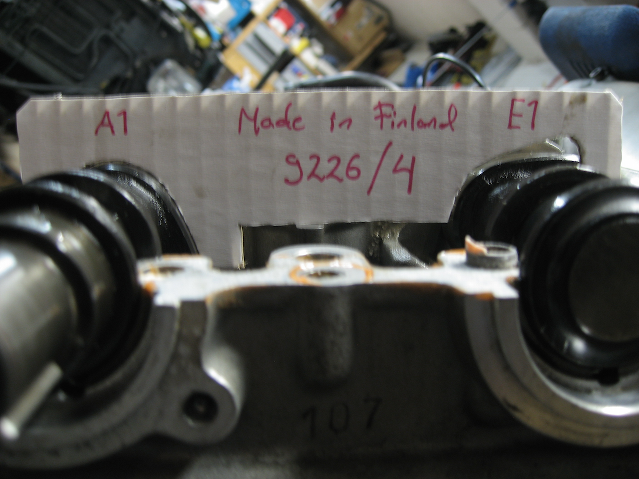
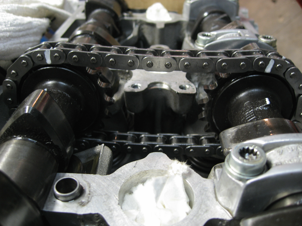
So, managed to hit the shack and reboot my camstuff. It kinda starts to go as routine, this time I even extra-cleaned them threads ; ok. So, the initial situation was that I paniced on 1-4 inlet and turned it one teeth (chain) advanced. Bad idea. Fresh-cut '9226' shows:
So, out it goes. After some time it starts to look like this:
Ok, mucho better. The tool took some hit as our 'jig' for testing 1-4 cam positions failed on us. Anyway, street credibility score raised on that tool.
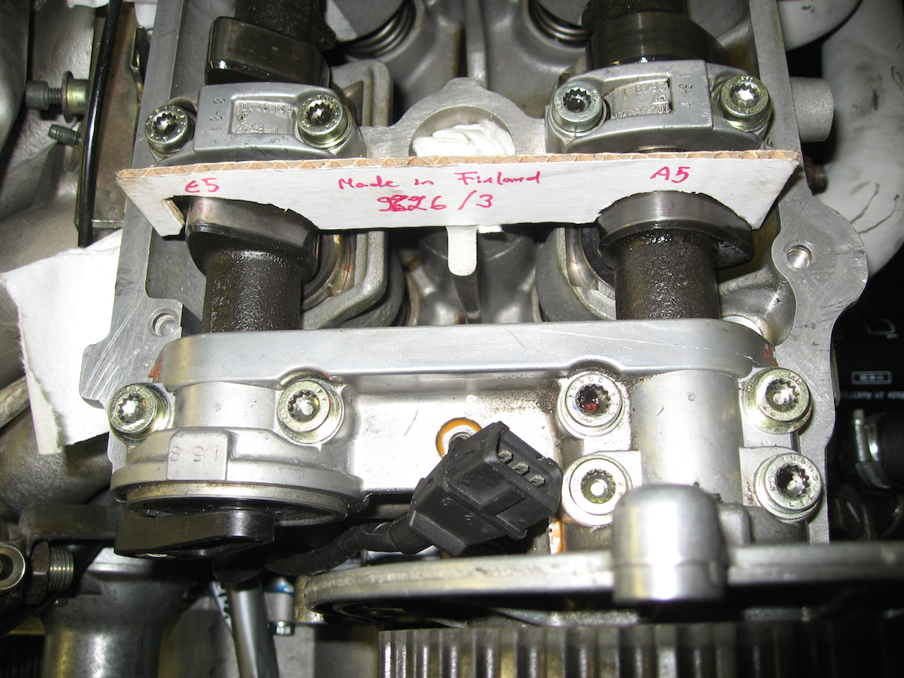
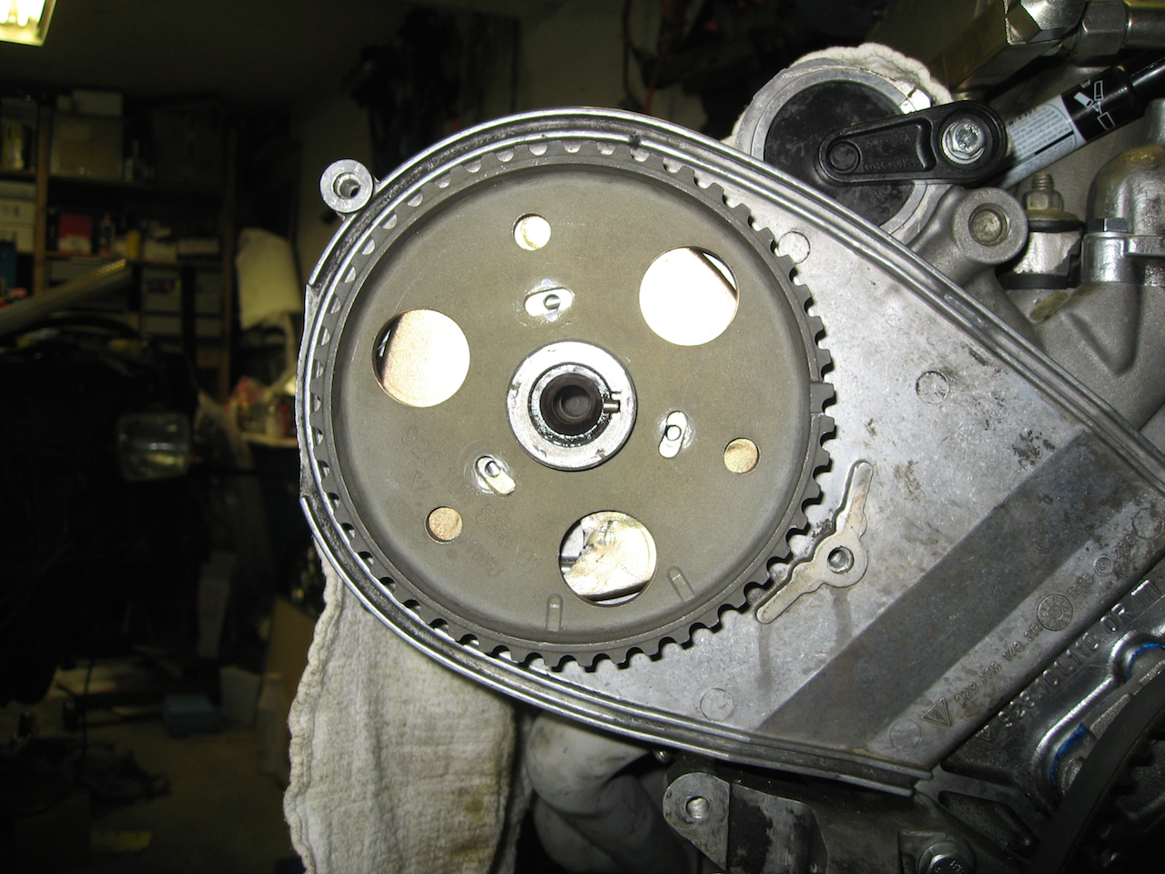
Next is 5-8, it looked like this before we started working on it:
So, it's like one tooth off! ARGH! Again the damn 928 outbeat me. I tried to be clever and determine based on cam position which of the markings is correct (there is a flat timing mark on that cam) - the pic reveals it. I did a wrong choise. Time to set it up with 9226 and:
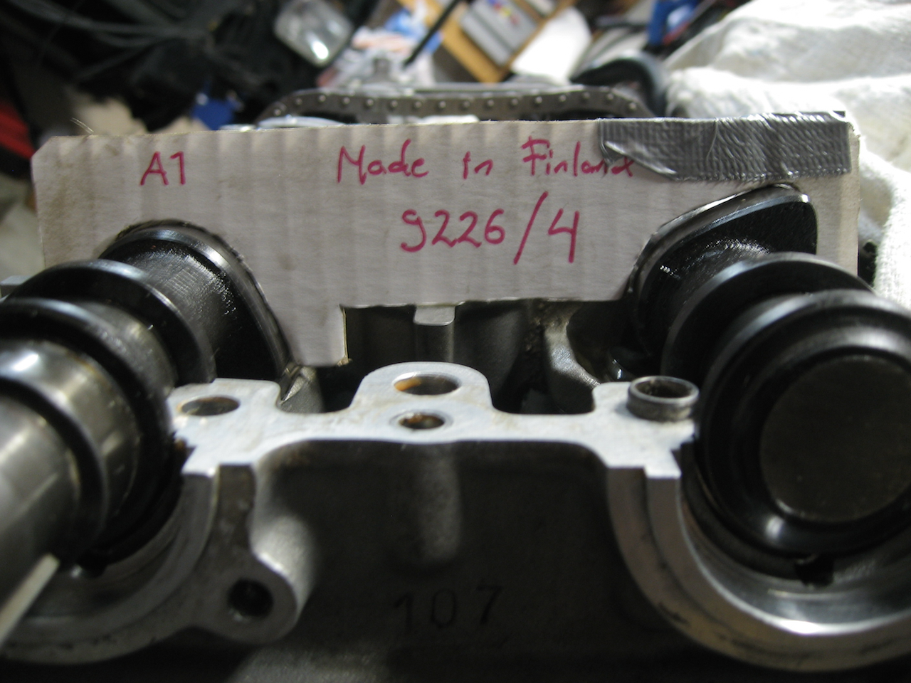
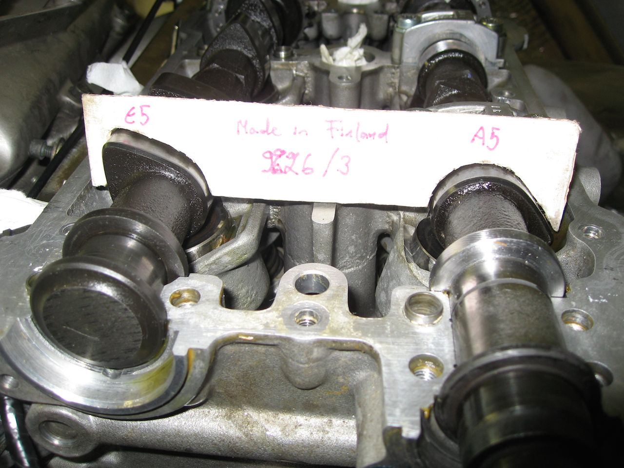
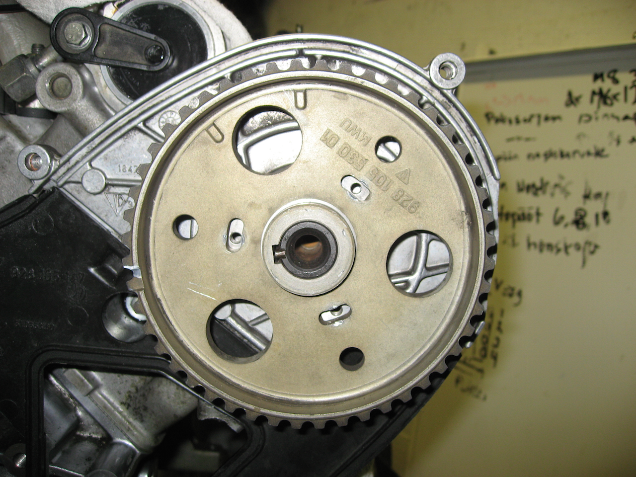
Okay. Much better. Both cams are now set and have 113mm clearance between the index marks and 7 links at the chain, like this (1-4 showing):
Finally, the cam sprockets are aligned as:
1-4:
and 5-8:
So we're now at 'reset state'. Crank is at 45 BTDC and cams are as-pre 9226.
So, what now? I went through the WSM and could not find 'install camshaft belt' for 32V engines. Is it exactly like 16V or is there a catch. The video (on this thread) is something I don't want to do.
Have you fitted the cam chain tensioners? Assuming this is the case you are ready to complete the procedure assuming the crank remains at 45 BTDC.
1. You will need 3 x5mm bolts for each cam wheel. I cannot remember the exact length but they are needed to lock the cam wheel to the cam shaft in the mid range position you show on your photos.
2. Fit the main bolt/hex washer and lock to 47 lb feet.
3. Now make a decision as to how you are going to install the cam belt - you can do this at the 45 BTDC position or, as the video shows with the cams at the TDC position.
4. If you use the 45 BTDC position [as I did] you rotate both cam sets until the indent on the cam wheel is 3 teeth before the notch aligns with the mark on the casing. Note when turning the cams you must use a spanner over the large hex washer- not the bolt]. I make a white paint mark on the tooth I intend to align with the notch on the casing. When both sides are indexed correctly I fit the belt and then tension it. At this point I remove the crank locking tool and then move the motor forward to top dead centre using the 27mm crank bolt- at this point I check that the marks on both cam wheels align with the mark on the casing and then turn the crank two full rotations and check again. If the marks align you are ready to go to the fine adjustment procedure for the cam timing wherein you use the clock gauges.
5. If you do not want to use step 4 above, with the crank still at 45 BTDC, you can mount the cam wheels as described in 4 above and then move both cam wheels forward until the indent aligns with the mark on the casing on both banks. Now remove the crank locking tool and rotate the crank to top dead centre position [as in the video], fit the timing belt, tension the belt and check that the marks align on both banks. Rotate the crank two full turns and check that the timing marks still align. You are now ready to adjust the fine tuning with the clock gauges.
You appear to understand the clock gauge procedure so no point in dwelling on that. I presume you understand that cam timing is set on No1 cylinder inlet valve for the 1/4 bank and on No6 cylinder inlet valve for bank 5/8.
Trust the above helps clarify. I am probably a bit paranoid about removing the crank locking tool at the 45 BTDC position without the timing belt fitted. You will also likely find that one of the cams will have a tendency to jump a bit under valve spring pressure and thus you may need to hold it in position with a spanner held by a friend when fitting the belt.
Managed to get to garage finally. Did the steps as per you told FredR. After some wrencing et al I can see 1.60 on #1 intake valve and 2.00 on #6 intake valve.
Whoa. Some experiment.
Tnx a million. FredR - ever in Finland ; you're bound to get a bottle of whiskey.
Managed to get to garage finally. Did the steps as per you told FredR. After some wrencing et al I can see 1.60 on #1 intake valve and 2.00 on #6 intake valve.
Whoa. Some experiment.
Tnx a million. FredR - ever in Finland ; you're bound to get a bottle of whiskey.
Jake,
Excellent news- pleased that we could be of some assistance and not confuse you too much!
Now that you have cracked it and have bench marked your timing accurately, it would be interesting to see what happens if you can get hold of Ken's 32VR cam timing tool and see what that shows. This kit makes cam timing adjustments so easy it is untrue- especially if you want to experiment with advancing and retarding the cam timing- I can do the job lot in an hour.
There has been discussion as to whether the 32VR kit can be relied on without having timed the cams like you just have [and I did] due to manufacturing differences. I have the GTS inlet cam mated to the S4 exhaust cam at the moment and they were timed initially using clock gauges. When I acquired the 32VR kit it showed timing to be spot on without any correction factor needing to be applied.
On a separate note you can help me a little if you can explain how you modified the camshaft [5/8 exhuast?] that needs a thrust collar. I can probably get this modification done here but need to monitor the work very carefully to ensure good quality assurance.
Look forward to reading about how well this cam package works in the S4 motor.

 10-08-2015, 03:08 AM
 ) during wknd.