When you click on links to various merchants on this site and make a purchase, this can result in this site earning a commission. Affiliate programs and affiliations include, but are not limited to, the eBay Partner Network.
I have a question regarding measuring the 16V heads before I take them in to be machined.
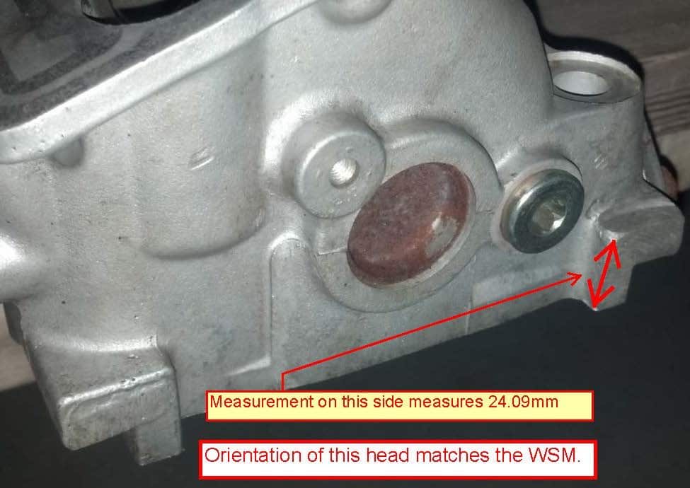
Page 15-19 of the WSM calls for the measurement at 'A' as shown in the picture below to be 24mm +/- 0.1mm when new. If you notice the WSM calls to take the dimension at one particular tab on the head (note the orientation shown). It doesn't call to take the dimension at the tab on the other side of the head or to even compare the two. My question is do I take the picture literally and only measure at that particular tab on the head?
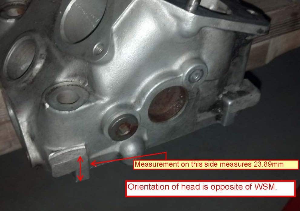
The reason I ask is that the dimension on the two tabs of the same head differ as shown on the pictures below. They also differ from this on the other head???
Before you ask, no the engine hasn't overheated so I don't think the head is warped, and in fact the head surface looks pretty good. I'm just thinking that it's probably best practice to have the surfaces machined and perfect before putting it all back together.
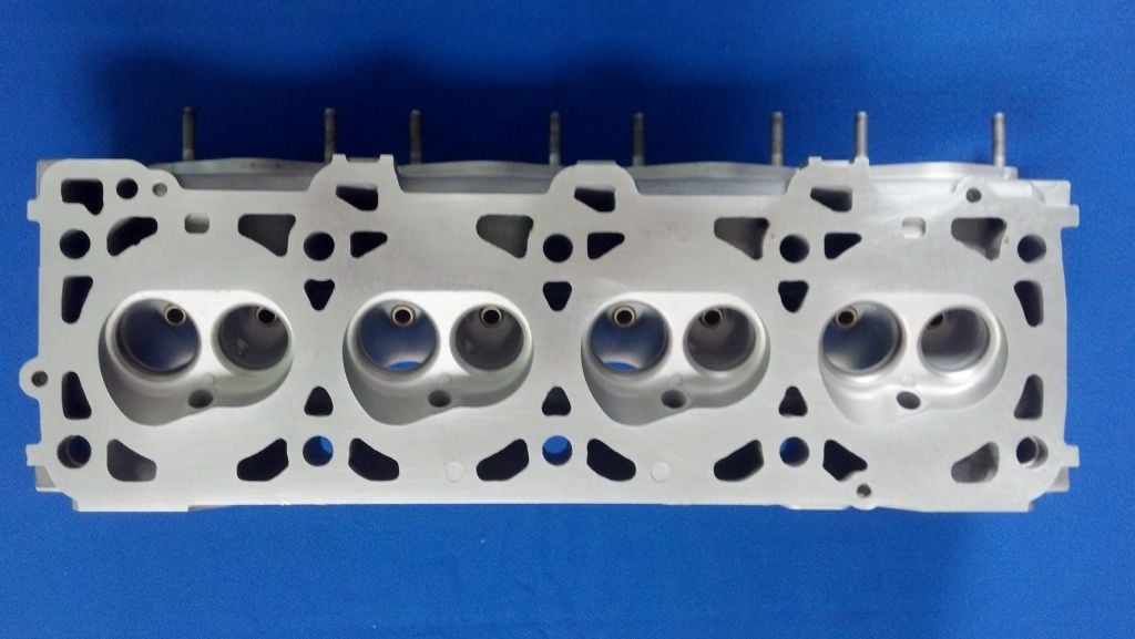
You'll find a machined flat on both ends of the head on the intake side, and two on the exhaust side (these are not on the corners like the intake side). I'm assuming that those are the set-up spot-faces for the original Porsche factory milling of the head casting. If you put the two heads on a bench and have ends oriented the same way, you'll see the spot face on the same side.
If the heads have never been machined, those should all be the same, so it really shouldn't matter which one you measure.
It's a good idea to set the heads up to measure for flatness and twist, and surface finish, to determine what needs to be taken off to restore the faces.
If the mating surface still looks good and the head is flat, don't machine it. Save it for when it actually needs it. Show us some pictures of the mating surface.
^^ agree. If visual inspection and measurement confirm that the surface is a flat undamaged plane, then a good clean of the surface should be all that's required. Only machine if essential to restore the surface.
Thanks, I'll post some pics tonight. The thing that bothers me is that the two machined tabs on the same head measure differently. If they were machined at the factory I would imagine that these measurements would be the same, unless you're supposed to take the image fro the WSM literally and only measure the head at that one tab? This engine has been worked on before by the PO's mechanic due to a timing belt failure and has all new exhaust valves. I'm just trying to figure out if they machined the heads and if so did they screw it up.
Thanks, I'll post some pics tonight. The thing that bothers me is that the two machined tabs on the same head measure differently. If they were machined at the factory I would imagine that these measurements would be the same, unless you're supposed to take the image fro the WSM literally and only measure the head at that one tab? This engine has been worked on before by the PO's mechanic due to a timing belt failure and has all new exhaust valves. I'm just trying to figure out if they machined the heads and if so did they screw it up.
If there was a fraction a mm upward/downward twist of the head at one tab point, then if the whole face was lightly skimmed on the same plane to get rid of that, it is possible to have very minor deviation between tabs. I had very minor deviation on a pair of heads I had done, between the four spot face points on each head (2 exhaust side + 2 intake side) after minimum surface facing. The fact that you have a variation between the front and back tabs on the intake side of one head, would indicate that it's likely the head was faced ... the measurements of the other two tabs on that head will give a clearer picture of what's been done.
I doubt you've got a problem, as you're still well within tolerance. ... but, post some pics, and list all the measurements of the tab thicknesses.
In this pic the red line on the right is a spot face line on the intake side at one end, and the two lines on the left are at the spot face points on the exhaust side, which are about 120mm in from each end.
When you measure from the spot face to the head surface, measure in several different locations and take the minimum, as handling the heads and bumping those areas can give minor distortion of the original flat reference surfaces ... and that can account for a little difference. A bump on the corner of the head can give a peak on the end of the spot face at that corner, and a consequential greater dimension.
Dave, thanks. I'll check all the dims and post my pictures and finding over the weekend.
Imre, I'll try to keep this as short as possible:
- I was getting oil in the intake so I put a temporary catch can on the engine.
- The catch can clamp slipped on the mounting bracket and must have closed off enough of the hose to cause compression in the engine as I blew the front main seal.
- Drained the oil and found a small amount of copper flecks in the oil.
- Pulled the engine, oil pan, and rod bearings and all looked good.
- Pulled the cradle and the metal flakes turned out to be from the thrust bearing (on a 5 speed!).
- Figured I went this far and pulled the heads.
- Found a strange wash pattern on the tops of the pistons that turns out was (probably) due to worn rings. The P&C's all measure well within tolerance (whew).
- Also found out that when the PO had a timing belt break that not only did their mechanic replace the exhaust valves, but that they most likely changed out a couple of pistons as well.
It's been good fun and a great learning experience. I'm just hoping to get this one successfully completed so I can start another more aggressive build this Fall.
MMM I too recently had the front seal hydraulic itself out of the front of the crank ,at a sprint day with the local Porsche club , with the result of oil everywhere.
It has had a persistent oil leak for over a year that I have not been able to find ,( It would appear that it had slowly been working its way out of its recess over this time) until this event , after the pull down I find that the seal , that was in the engine , whilst looking in perfect condition , was 0.23mm smaller than a spare that had in my collection , this could just be due to the fact that it was compressed .
However all the engine components , are in excellent condition , compression from 200 to 218 psi cold , as this engine is in a car that is regularly on the track , and run with motorsport tyres, it is interesting to find another car with a similar problem , that is difficult to explain.
I am going to try and modify the breathing system , as too experiment , but other than that am scratching my head.
Oh and this is the 5 litre GT car .
Ron,
Yea I've had a run a bad luck with the car the last couple of years so I haven't gotten to SITM but I'm hoping to make Frenzy this fall.
John,
I'm pretty sure that when I lost the front main seal it was caused by over pressurization of the case. I think there have been others here who had similar experiences with clogged breather systems having a similar outcome.
I just couldn't leave well enough alone and took my heads to the machine shop where they did a pretty good job of cleaning everything up. It doesn't appear that they were able to get the heads perfectly flat but from one side to the other I guess I can live with .007"
I just couldn't leave well enough alone and took my heads to the machine shop where they did a pretty good job of cleaning everything up. It doesn't appear that they were able to get the heads perfectly flat but from one side to the other I guess I can live with .007"
Looking good! I have a similar perfectionist mindset You're going to get a great overall result
Aim for perfect and you won't always achieve it, but you'll get very very close ... aim for close enough, and you'll usually end up with s**t.

 07-01-2015, 10:20 PM